ALPHA DS & DH DIESEL DISPENSER - Hytek
ALPHA DS & DH DIESEL DISPENSER - Hytek
ALPHA DS & DH DIESEL DISPENSER - Hytek
- No tags were found...

Create successful ePaper yourself
Turn your PDF publications into a flip-book with our unique Google optimized e-Paper software.
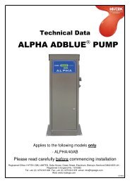
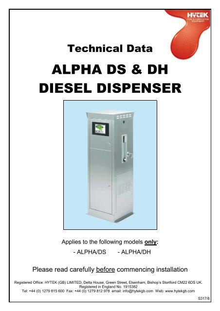
Technical Data<strong>ALPHA</strong> <strong>DS</strong> & <strong>DH</strong><strong>DIESEL</strong> <strong>DISPENSER</strong>Applies to the following models only:- <strong>ALPHA</strong>/<strong>DS</strong> - <strong>ALPHA</strong>/<strong>DH</strong>Please read carefully before commencing installationRegistered Office: HYTEK (GB) LIMITED, Delta House, Green Street, Elsenham, Bishop’s Stortford CM22 6<strong>DS</strong> UK.Registered in England No. 1915382Tel: +44 (0) 1279 815 600 Fax: +44 (0) 1279 812 978 email: info@hytekgb.com Web: www.hytekgb.comS317/8
ENVIRONMENTAL INFORMATIONEuropean Directives 2002/96/EC and 2003/108/EC requirethat the equipment bearing this symbol on the productan/or its packaging must not be disposed of with unsortedmunicipal waste. The symbol indicates that this productmust be disposed of separately from regular householdwaste streams. It is your responsibility to dispose of thisand other electric and electronic equipment via designatedcollection facilities appointed by the government or localauthorities.IMPORTANT WARNING NOTES1. This dispenser MUST NOT be used to dispense petrol or otherflammable liquids.2. It must not be sited adjacent to a petrol dispenser or in any otherhazardous zone.3. On above ground storage tanks an angle check valve fitted with theappropriate spring or pressure regulating valve must be fitted at the tankoutlet to prevent loss of fuel under gravity in the event of vandalism oraccidental damage.4. Installation of this equipment and its associated tank, pipe work andfittings should only be carried out by qualified fuel installation engineers.5. The installation must conform to all relevant electrical and local authorityregulations and standards.6. It must not be used with other liquids or for other applications. We willaccept no warranty claims or liability if it is used for other liquids orapplications.CALIBRATIONThe meter on this pump unit must be calibrated electronically to ensureaccuracy and reliability. See page 7 for instructions on how to carry out thisprocedure.S317/8
INSTALLATION INSTRUCTIONS1. Check you have the following items:1 off Alpha dispenser1 off delivery hose1 off panel key2. Open the front panel using the key provided.3. Remove the rear panel, if necessary, and store safely.MOUNTING4. Bolt the dispenser to a firm level foundation by means of the four 14 mmdiameter-mounting holes provided.NB: If the optional drip tray is to be fitted to the dispenser it must besealed to its foundation, with a suitable elastomeric substance,to prevent leaked fuel "wicking" back underneath the dispenser.To maintain the environmental integrity of the drip tray anypossible leak path through the dispenser mounting holes mustalso be sealed.PUMPED FUEL SUPPLY5. The fuel supply to the dispenser must not exceed a pressure of 2.7 bar(40PSI) with a maximum flow rate of 70 litres per minute for the<strong>ALPHA</strong>/<strong>DS</strong> and 90 litres per minute for the <strong>ALPHA</strong>/<strong>DH</strong>.PIPEWORK6. Connect the pipe from the pump to the inlet of the dispenser. It isrecommended that a shear valve, fitted with double spring loadedpoppets, is installed at ground level to prevent fuel leakage in the eventof the dispenser being pulled / knocked over. The bracket fitted to thedispenser base provides a means of securely anchoring the inlet pipe inposition if necessary.Seal the joints with a suitable thread-sealing compound. The pipe workmust be sealed to the drip tray (if fitted) to ensure no leaked fuel can flowunderground. An alternative pipe work entry point, for above ground pipework, is provided at the rear of the dispenser base.S317/8
7. Connect one end of the delivery hose into the outlet elbow. Ensure thenylon hose-sealing washer is in place on the hose end. It should be handtight plus a quarter turn.8. Screw the nozzle onto the other end of the hose, again ensuring thenylon washer is in place. No other sealing compound is necessary. Handtight plus a quarter turn.ELECTRICAL9. Remove the covers from the 220/240V supply and the external pulseoutput connection junction boxes.10. Connect a constant 220/240V AC 50 Hz supply, fused at 16 amps, tothe terminal block in the 220/240V supply junction box as shown on thewiring details diagram.NB:The Alpha dispenser must have a continual 220/240V ACsupply, even when not in use11.If the Alpha is to be operated in conjunction with a key/card system,remove the link in the 220/240V supply junction box (shown on the AlphaInstallation Wiring Diagram) and connect so that the control systemmakes and breaks the connection.Make connection – Solenoid valve openBreak connection - Solenoid valve closedAlternatively remove the link and connect a switched live supply (230VAC 16A max.) to terminal 4 (shown on Alpha Inst. Wiring Diagram)Live supply switched on - Solenoid valve openLive supply switched off - Solenoid valve closed12. A pulse output for connection to key/card systems is available from thepair of terminals located in the separate pulse output connection junctionbox. This is a passive contact giving 10 or 100 pulses per litre. Contactratings are as follows:Maximum current - 0.25 ampsMaximum voltage - 50 voltsMaximum power - 5 VA13. Ensure all the terminal screws are tight and replace the junction boxcovers.S317/8
INSTRUCTIONS FOR USE1. Remove the nozzle from the holster.2. Place the nozzle spout in the fuel tank.3. Squeeze the nozzle trigger to dispense fuel.On completion of the delivery release the trigger and replace the nozzlein the holster.MAINTENANCEThe Alpha should require minimum maintenance in normal regularuse, but as with all mechanical apparatus regular servicing willprolong it’s life and ensure maximum efficiency & reliability.The following should be carried out every 12 months or 1 millionlitres which ever comes first.- Isolate power supply- Inspect & clean or replace inlet filter- Inspect & clean or replace nozzle filter- Re-calibrate electronic displayS317/8
ALP.DISP2 ELECTRONIC DISPLAY/CALCULATORFEATURES6-digit backlit Main LCD display:8-digit backlit totaliser LCD display:Up to 9999.99 or 99999.9 litres perdeliveryUp to 99999999 litresDisplay retained during power failureOPERATIONStand-by mode:Nozzle removed:Fuel drawn:Nozzle Returned:Main LCD display shows previous deliveryTotaliser LCD display shows ongoing totalMain LCD display shows “all eights” then “all zeros”Totaliser LCD display shows “FUELLING”Pump startsMain LCD display shows litres dispensedTotaliser LCD display shows “FUELLING”Pump stopsMain LCD display shows previous deliveryTotaliser LCD display shows ongoing totalS317/8
CALIBRATION PROCEDURE - (MUST BE CARRIED OUT TOENSURE PUMP ACCURACY)1. Ensure the nozzle is stowed in the holsterand the dispenser is isolated from anyfuel management systems.2. Remove calibration button cover bolt fromrear of display / calculator housing (iffitted).3. Gently push and hold the calibrationbutton using a small screwdriver orsimilar tool.S317/8
4. Release the calibration button when thetotaliser display shows VER followed bythe version number on the lower display.00000.0VER 0.1305. The totaliser display will show thefollowing in a looping sequence:CH 1 - Single channel pulser connectedCH 2 - Two channel pulser connectedREED - Reed switch pulser connected00000.0CH 1Press calibration button once whendesired option is displayed.Select CH 2 for Weights & MeasuresAlpha, REED for Alpha fitted withPULS.E18 reed switch pulser (preAugust 2003) or Adblue Alpha andCH 1 for all other Alpha versions.6. The totaliser display will show thefollowing in a looping sequence:1 DP - One decimal place on display2 DP - Two decimal places on displayPress calibration button once whendesired option is displayed.00000.01 DP7. The totaliser display will show thefollowing in a looping sequence:RELAY 10 - Ten pulse per litre reedrelay output.OPTO 10 - Ten pulse per litre optoisolatedoutput.OPTO 100 - One hundred pulse per litreopto-isolated output.Press calibration button once whendesired option is displayed.00000.0OPTO 10S317/8
8. The totaliser display will show thefollowing in a looping sequenceSTD ALONE - Pump external serialinterface not used.NET - To set the pump identity number(1-8) if serial interface used to connectto a fuel control system.EXT ID - To set the pump identitynumber (1-16) if serial interface used toconnect to fuel control system.Press calibration button once whendesired option is displayed.a. If NET or EXT ID were selectedabove, the pump identity number mustbe selected from the looping sequence.Press calibration button once whendesired option is displayed.00000.0STD ALONE00000.0ID 5b. The totaliser display will show thefollowing in a looping sequence:BR 9600 RS485 communicationBaud rate 9600BR 19200 RS485 communicationBaud rate 19200BR 38400 RS485 communicationBaud rate 3840000000.0BR 96009. If STD ALONE was pressed in 8. abovethe totaliser display will show NOZZLE.To save any changes made so far but toavoid carrying out the following 20 litrecalibration, press the calibration buttononce to continue directly to point 12.below.00000.0NOZZLES317/8
10. Take nozzle. The totaliser display willshow FUELLING and the pump willstart. When main display shows 000000dispense precisely 20 litres of fuel(using a measure can).The main display will show pulsesclocking up.000000FUELLING20L11. Hang the nozzle back into the holster.12. If the totaliser display shows CALIB OKpress the calibration button for twoseconds to return to normal operation.The Alpha dispenser is now calibrated.If the totaliser shows CAL FAIL orERROR press the calibration button fortwo seconds to return to normaloperation. The Alpha dispenser hasNOT been calibrated. Repeatcalibration procedure.001 186CALIB OKS317/8
ERRORSIf an error occurs ERROR (followed by a number) is shown on thetotaliser display. The error codes are classified as follows:ERROR 1ERROR 2ERROR 3ERROR 4ERROR 5ERROR 6The pulser has run too fast (in excess of 300 pulsesper second)The meter has turned without the nozzle beingremovedA time delay of 60 seconds or more has occurredbetween any of the stages of the calibration sequenceOne of the pulse transmitter’s pulse trains has beeninterrupted.The meter has run backwards during a deliveryThe pulser has been disconnectedThe error condition is maintained until the nozzle is returned to itsholster, for at least 2 seconds, and then removed again to restart thefuelling sequence.DISPLAY CONNECTION DIAGRAM220/240 VACPOWERINPUT220/240 VACMOTOR RELAYOUTPUTLIVEEARTHNEUTRALNEUTRAL - WHITELIVE - BLACK1 2 31 2DISPLAY /CALCULATORVIEWED FROMREAR1 2 3DATA 1DATA 2GROUNDCALIBRATION BUTTONRS485 SERIALINTERFACECONNECTOR(WHITE 3 PIN)1 21 2 3 1 21 2 1 2 3 4COMMON - BROWNREED RELAY - BLUEOPTO ISOLATED - GRN/YEL+12VDC - BROWN0V - BLUEBLUE/GREENYELLOW+12VDC - RED (W&M GREEN)CH 1 - YELLOW (W&M WHITE)CH 2 - GREEN (W&M YELLOW)0V - BLACK (W&M BROWN)AND SCRN10:1 /100:1PULSEOUTPUT12V DC SOL. NOZZLEOUTPUT SWITCH(WEIGHTS & INPUTMEASURESVERSIONONLY)PULSETRANSMITTERINPUTS317/8
<strong>ALPHA</strong> <strong>DISPENSER</strong> BASE AND INLET CONNECTIONSBASE VIEW FROMABOVE30526500FRONT13ALL DIMENSIONS IN MMFOUR 14MM DIA. MOUNTING HOLESOPTIONAL DRIP TRAY178322TWO 35MM DIA.CABLE ENTRYHOLES (PLUNGED)45639665MM DIA. INLETHOLE (PLUNGED)ALIGNED WITHLEVER BALLVALVE INLET10014788REAR VIEW1 1/2" LEVER BALL VALVE(SUPPLIED AS STANDARD)76.5MM DIA.ALTERNATIVEINLET HOLE1 1/2" BSP FEMALETHREAD ALIGNEDWITH HOLE IN BASE50225SHEAR VALVE LOCATED WITHSHEAR SECTION AT FINISHEDGROUND LEVEL<strong>ALPHA</strong> INSTALLATION WIRING DIAGRAM5423583TWO 22MM DIA. ALTERNATIVECABLE ENTRY HOLESCONNECTIONS IN 220/240V JUNCTION BOX230VMOTOROUTPUTAUTH. 220-240VINPUTALTERNATIVE PUMPCONTROL - KEY/CARD LCONTROL SYSTEMSWITCHED LIVE SUPPLY220/240V AC 16 A MAXELN1 2 345*L6N7E8KEY/CARD CONTROLSYSTEM RELAY220/240V AC16A MAX*SUPPLIED WITH LINK FITTED BETWEEN TERMINALS 4 AND 5.REMOVE LINK FOR REMOTE KEY/CARD CONTROLENLCONSTANT SUPPLY220 / 240V ACFUSE - 16AS317/8
<strong>ALPHA</strong> EXTERNAL DIMENSIONS580 MM515 MM630 MM515 MM457 MM155 MM155 MMFRONTNOZZLEVERSION1410 MM<strong>ALPHA</strong>865 MM832 MM832 MMS317/8
<strong>ALPHA</strong> <strong>DS</strong>/<strong>DH</strong> EXTERNAL VIEW81 112 3510967S317/8
<strong>ALPHA</strong> PARTS LISTREF PART DESCRIPTION PART NO. <strong>DS</strong> PART NO. <strong>DH</strong>EXTERNAL COMPONENTS1 LCD DISPLAY UNIT ALP.DISP2.R ALP.DISP2.R2 LOCK (x 2) 209.LOCK 209.LOCK3NOZZLE HOLSTER WITHSWITCHALP.NOZBOOT.A ALP.NOZBOOT.A4 DOOR KEY 209.KEY 209.KEY5 OUTLET ELBOW ELB.4FFCR ELB.4FFCR6 SIDE ACCESS PANEL ALP.ACCPAN.MK2 ALP.ACCPAN.MK27 MOUNTING BASE ALP.BASE ALP.BASE8 TOP CAP ALP.CAP ALP.CAP9 DOOR ALP.DOOR ALP.DOORDOOR (FRONT NOZZLEOPTION)*ALP.DOOR.F ALP.DOOR.F10 SIDE PANEL ALP.SPAN.BL ALP.SPAN.BL11SIDE PANEL WITH HOSEOUTLETALP.SPANH.MK2 ALP.SPANH.MK2SIDE PANEL WITH HOSEOUTLET (FRONT NOZZLEOPTION)ALP.SPANH.F ALP.SPANH.FINTERNAL COMPONENTS12 DOOR STAY * ALP.<strong>DS</strong>TAY ALP.<strong>DS</strong>TAY13 PULSER* PULS.30A PULS.30A154 PISTON METER (2 REVPER LITRE)*209A.METER 209A.METER16 METER OUTLET PIPE* ALP.OUTPIPE.W ALP.OUTPIPE.W17 METER INLET GASKET* ALP.GSK.MET ALP.GSK.MET18 INLET STRAINER* YSTR.15A YSTR.15A19RELAY (INSIDE JUNCTIONBOX)*ALP.RELAY ALP.RELAY20 UPPER PANEL (x 2)* ALP.UPAN ALP.UPAN21 DISPLAY COVER* ALP.DISPCOV2 ALP.DISPCOV222PUMP MOUNTING FRAME(x 2)*ALP.PFRAME ALP.PFRAME23EXTERNAL PULSEOUTPUT BOX*JBOX.SPTERM JBOX.SPTERM24 JUNCTION BOX* ALP.JBOX2 ALP.JBOX225 OUTLET CHECK VALVE* CHK.1A.DRILL CHK.1A.DRILL26 INLET SOLENOID VALVE* ALP.SOL ALP.SOL27 INLET LEVER BALL VALVE LBV.6A LBV.6A28 UNDER PUMP SHEAR VLV* SVDPA*Not shown on illustrationSVDPAS317/8
E.C. DECLARATION OF CONFORMITYDate of Issue: 12 th March 2009Equipment Details:Alpha Fuel Dispensers<strong>ALPHA</strong>/<strong>DH</strong>, <strong>ALPHA</strong>/<strong>DS</strong>Applicable standards:EMCEN50081-1:1992EN50082-1:1997EN61000-3-2:1995 +A12EN61000-3-3:1995EmissionsImmunityEmissionsEmissions2006/95/EC Electrical Equipment (Low Voltage)Machinery Directive 98/37/EC (2006/42/EC)The Pressure Equipment Regulations1999 S.I. 1999/2001Entry Into Force: 29 November 1999Amended to S.I. 2002/1267Pressure Equipment Directive 97/23/ECWaste Electrical and Electronic EquipmentRegulations 20062002/96/EC 2003/108/ECAuthorized By:Declaration Number:Clive WellingsEC029/5S317/8