SERVICE MANUAL - HWH Corporation
SERVICE MANUAL - HWH Corporation
SERVICE MANUAL - HWH Corporation

You also want an ePaper? Increase the reach of your titles
YUMPU automatically turns print PDFs into web optimized ePapers that Google loves.
R<br />
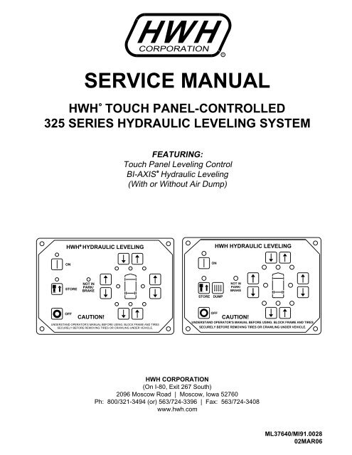
<strong>SERVICE</strong> <strong>MANUAL</strong><br />
<strong>HWH</strong> TOUCH PANEL-CONTROLLED<br />
325 SERIES HYDRAULIC LEVELING SYSTEM<br />
R<br />
<strong>HWH</strong> CORPORATION<br />
R<br />
FEATURING:<br />
Touch Panel Leveling Control<br />
R<br />
BI-AXIS Hydraulic Leveling<br />
(With or Without Air Dump)<br />
<strong>HWH</strong> HYDRAULIC LEVELING<br />
<strong>HWH</strong> HYDRAULIC LEVELING<br />
ON<br />
ON<br />
STORE<br />
NOT IN<br />
PARK/<br />
BRAKE<br />
STORE<br />
DUMP<br />
NOT IN<br />
PARK/<br />
BRAKE<br />
OFF<br />
CAUTION!<br />
UNDERSTAND OPERATOR’S <strong>MANUAL</strong> BEFORE USING. BLOCK FRAME AND TIRES<br />
SECURELY BEFORE REMOVING TIRES OR CRAWLING UNDER VEHICLE.<br />
OFF<br />
CAUTION!<br />
UNDERSTAND OPERATOR’S <strong>MANUAL</strong> BEFORE USING. BLOCK FRAME AND TIRES<br />
SECURELY BEFORE REMOVING TIRES OR CRAWLING UNDER VEHICLE.<br />
<strong>HWH</strong> CORPORATION<br />
(On I-80, Exit 267 South)<br />
2096 Moscow Road | Moscow, Iowa 52760<br />
Ph: 800/321-3494 (or) 563/724-3396 | Fax: 563/724-3408<br />
www.hwh.com<br />
ML37640/MI91.0028<br />
02MAR06
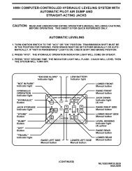
SECTION 1<br />
SECTION<br />
1<br />
SYSTEM<br />
OPERATION<br />
AND TROUBLE<br />
SHOOTING<br />
GUIDE<br />
SECTION<br />
2<br />
DIAGRAMS<br />
AND<br />
GLOSSARY<br />
2 PART FOLDER<br />
HOW TO USE <strong>MANUAL</strong><br />
This manual is written in two sections. Section 1 is System Operation and Trouble Shooting Steps. Section 2 is the<br />
Diagrams and Parts Glossary. Begin diagnosis of the system with Section 1. This will give the correct operation and function<br />
of the system. The Trouble Shooting Steps are written in order of operation. The Trouble Shooting Steps should be followed<br />
in order to avoid improper diagnosis of the system. Section 2 contains diagrams and a parts glossary. Refer to diagrams as<br />
directed in the Trouble Shooting Steps. The parts glossary explains the function of individual parts.<br />
IMPORTANT: Plumbing and wiring diagrams are generic in nature. Refer to specific owner’s manuals when available<br />
or contact <strong>HWH</strong> <strong>Corporation</strong> for specific diagrams when necessary.<br />
Before beginning your repair, it is IMPORTANT to read the CAUTIONS and NOTES AND CHECKS in the first section, TROUBLE<br />
SHOOTING GUIDE. In many cases this will save time and mistakes when trouble shooting a system.<br />
This Repair Manual is offered as a guide only. It is impossible to anticipate every problem or combination of problems. For<br />
any problems encountered that are not addressed in this manual, contact <strong>HWH</strong> <strong>Corporation</strong> for assistance. (800-321-3494)<br />
PROCEED WITH SYSTEM OPERATION<br />
MI91.1132<br />
01NOV11
TROUBLE SHOOTING<br />
WARNING!<br />
BLOCK FRAME AND TIRES SECURELY BEFORE CRAWLING UNDER VEHICLE. DO NOT USE THE LEVELING<br />
JACKS OR AIR SUSPENSION TO SUPPORT VEHICLE WHILE UNDER VEHICLE OR CHANGING TIRES. VEHICLE<br />
MAY DROP AND OR MOVE FORWARD OR BACKWARD WITHOUT WARNING CAUSING INJURY OR DEATH.<br />
WHEN ROUTING OR REROUTING HYDRAULIC HOSES AND WIRES, BE SURE THEY ARE NOT EXPOSED TO ENGINE<br />
EXHAUST OR ANY HIGH TEMPERATURE COMPONENTS OF THE VEHICLE.<br />
NEVER PLACE HAND OR OTHER PARTS OF THE BODY NEAR HYDRAULIC LEAKS. OIL MAY CUT AND<br />
PENETRATE THE SKIN CAUSING INJURY OR DEATH.<br />
SAFETY CLASSES ARE TO BE WORN TO PROTECT EYES FROM DIRT, METAL CHIPS, OIL LEAKS, ECT. FOLLOW<br />
ALL OTHER SHOP SAFETY PRACTICES.<br />
NOTES AND CHECKS<br />
Read and check before proceeding with Trouble Shooting Steps.<br />
NOTE: <strong>HWH</strong> CORPORATION ASSUMES NO LIABILITY<br />
FOR DAMAGES OR INJURIES RESULTING FROM THE<br />
INSTALLATION OR REPAIR OF THIS PRODUCT.<br />
1. If the jacks cannot be retracted, see TROUBLE SHOOTING<br />
PART 15 Step 2 for temporary measures. Make sure the<br />
manual retract valves are closed before trouble shooting.<br />
2. The Trouble Shooting Guide must be followed in order.<br />
Problems checked for in one step are assumed correct and<br />
may not be checked again in following steps.<br />
3. Check that the oil reservoir is full with the jacks in the fully<br />
retracted position. If the vehicle is equipped with <strong>HWH</strong> room<br />
extensions, refer to the <strong>HWH</strong> Owners Manual for proper<br />
position of the room when checking the oil level.<br />
4. Most coaches have more than one battery; one for the engine<br />
and the other(s) for the coach. The engine battery supplies<br />
power for the control box and hydraulic pump. Batteries under<br />
no load should read 12.6 volts. Batteries must maintain good<br />
voltage under load. Batteries must be in good condition with<br />
no weak cells. An alternator, converter or battery charger will<br />
not supply enough power for the system to operate properly.<br />
5. Proper grounding of all components is critical. See the<br />
electrical circuit for specific grounds required. Faulty grounds,<br />
especially for the control box, solenoid manifold or the pump<br />
assembly, may cause control box component damage and /or<br />
improper or erratic operation.<br />
6. Do not replace the control box unless the Repair Steps say<br />
to replace it. Otherwise the malfunctions may damage the<br />
new control box.<br />
This manual is intended for use by experienced mechanics<br />
with knowledge of hydraulic and automotive electrical<br />
systems. People with little or no experience with <strong>HWH</strong><br />
leveling systems should contact <strong>HWH</strong> technical service<br />
(800-321-3494) before beginning. Special attention should<br />
be given to all cautions, wiring, and hydraulic diagrams.<br />
Special note: When installing a new control box, make<br />
sure the box is properly grounded before applying power<br />
to the system.<br />
Tightening of hose ends: If tightening a new hose end,<br />
make the hose end snug (finger tight) on the fitting, then<br />
tighten the hose end 1/3 turn (2 FLATS). If tightening an<br />
existing hose end, tighten the hose end to snug plus 1/4<br />
turn (1 FLAT).<br />
Suggested tools for trouble shooting the <strong>HWH</strong> leveling systems:<br />
JUMPER WIRES (UP TO 10 GAUGE)<br />
PRESSURE GAUGE (3500 PSI MIN.)<br />
MULTI-METER<br />
12 VOLT TEST LIGHT<br />
PROCEED WITH THE TROUBLE<br />
SHOOTING STEPS ON THE<br />
FOLLOWING PAGE<br />
MI91.1142<br />
25APR11
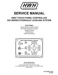
CONTROL IDENTIFICATION<br />
325 SERIES LEVELING SYSTEM<br />
TOUCH PANEL-CONTROL<br />
LEFT SIDE EXTEND<br />
BUTTON<br />
POWER ON LIGHT<br />
"ON" BUTTON<br />
STORE LIGHT<br />
"STORE" BUTTON<br />
"DUMP" BUTTON<br />
"OFF" BUTTON<br />
LEFT SIDE RETRACT<br />
BUTTON<br />
STORE<br />
ON<br />
<strong>HWH</strong> HYDRAULIC LEVELING<br />
DUMP<br />
OFF<br />
NOT IN<br />
PARK/<br />
BRAKE<br />
CAUTION!<br />
UNDERSTAND OPERATOR’S <strong>MANUAL</strong> BEFORE USING. BLOCK FRAME AND TIRES<br />
SECURELY BEFORE REMOVING TIRES OR CRAWLING UNDER VEHICLE.<br />
FRONT RETRACT BUTTON<br />
FRONT EXTEND BUTTON<br />
WARNING LIGHTS (4-Red)<br />
RIGHT SIDE EXTEND BUTTON<br />
RIGHT SIDE RETRACT BUTTON<br />
LEVEL LIGHTS (4-Yellow)<br />
REAR EXTEND BUTTON<br />
REAR RETRACT BUTTON<br />
CONTROL FUNCTIONS<br />
ON (I) BUTTON: This is the on button for the leveling<br />
system. The on indicator light is above the (I) button.<br />
"OFF" BUTTON:<br />
operation.<br />
CONTROL BUTTONS<br />
Push the "OFF" button to stop hydraulic<br />
"STORE" BUTTON: The store indicator light is above the<br />
"STORE" button. This button is used to automatically retract<br />
the jacks.<br />
EXTEND BUTTONS (UP ARROWS): These buttons will<br />
extend their respective jack pairs to lift the vehicle.<br />
RETRACT BUTTONS (DOWN ARROWS): These buttons<br />
will retract their respective jack pairs to lower the vehicle.<br />
DUMP BUTTON: (IF APPLICABLE) This button will dump<br />
the air from the vehicle suspension.<br />
INDICATOR LIGHTS<br />
HYDRAULIC OPERATIONS (I) LIGHT: This light indicates<br />
that the panel is active.<br />
"NOT IN PARK/BRAKE" LIGHT: This indicator will light<br />
when the hand/auto brake is not set and the "LEVEL"<br />
button is being pushed.<br />
STORE LIGHT: This light indicates that the system<br />
is in STORE mode.<br />
LEVELING LIGHTS: The four yellow indicating lights are<br />
level sensing indicators. When a yellow light is on, it<br />
indicates that its side, end, or corner of the vehicle is low.<br />
No more than two lights should be on at the same time.<br />
JACK DOWN LIGHTS: The four red lights surrounding the<br />
yellow level indicators are jacks down WARNING lights.<br />
They are functional only when the ignition is in the "ON"<br />
or "ACC" position, the system is on, and the jacks are<br />
extended 1/4 to 1/2 inch.<br />
MASTER "JACKS DOWN" WARNING LIGHT: This is a<br />
light mounted in the dash separate from the touch panel.<br />
It will be on when any one or more jacks are extended<br />
and the ignition is "ON".<br />
BUZZER: This is a jacks down warning. It will sound if the<br />
master "JACKS DOWN" warning light is on.<br />
MI91.3250<br />
24FEB06
SYSTEM OPERATION<br />
The 325 leveling system is a manually controlled, BI-AXIS push-button system. This system will always extend two [2] jacks<br />
at the same time, both front jacks, the left front and the left rear jacks, the right front and right rear jacks or both rear jacks.<br />
The jacks are controlled by the UP and DOWN arrow buttons on the right hand side of the touch panel. The UP arrows<br />
extend jack pairs and the DOWN arrows retract jack pairs.<br />
There are two parts to leveling a vehicle. First the vehicle is leveled. The jacks are used to turn all the yellow level indicators<br />
off. The second part of leveling is to stabilize the vehicle. This is accomplished by extending any jacks not used for leveling to<br />
the ground and lifting the vehicle about ¾ to 1 inch.<br />
The ignition must be in the "ON" or "ACC." position and the park brake must be set to turn the system on. The "NOT IN<br />
PARK/BRAKE" indicator light will come on while the "ON" button is being pushed if the park brake signal is not present. The<br />
system will not turn on.<br />
Pushing the "ON" (I) button will turn the system on. The POWER ON light should be lit. With the POWER ON light on,<br />
the UP and DOWN arrows will function. The "DUMP" button will function at this time.<br />
If the vehicle is equipped with an air suspension, the air must be exhausted from the suspension before leveling the vehicle. If<br />
the air is not exhausted, the suspension height control valves will interfere with the leveling procedure. There are two types of<br />
air dump systems that <strong>HWH</strong> controls. One system uses air solenoid valves supplied by <strong>HWH</strong>. The second system is supplied<br />
by the chassis manufacturer. This is a pilot air dump system. The <strong>HWH</strong> touch panel has a "DUMP" button. The "DUMP"<br />
button will only work if the POWER ON light is on. If the vehicle uses the <strong>HWH</strong> air dump pilot air dump system is used, the<br />
engine may be on or off. The "DUMP" button can be pushed and released. The pilot air dump system will return to the travel<br />
position if the ignition is on and the "STORE" button is pushed or the park brake is released.<br />
NOTE: Releasing the park brake to return the suspension to travel mode (vehicle to ride height) is not recommended<br />
for normal operation. This is a fail safe if the "STORE" button is not used to retract the jacks.<br />
<strong>MANUAL</strong> LEVELING OPERATION<br />
On the right hand side of the touch panel there are four (4) red and four (4) yellow indicator lights. The four red indicator lights<br />
are JACK DOWN warning lights. There is one light for each jack. These warning lights come on when their respective<br />
straight-acting jacks are extended about ¼ to ½ inch or a kick-down jack is in the vertical position. The four yellow indicator<br />
lights are level indicators, front, left side, right side and rear. A lit yellow level light indicates that a side, end or corner is low.<br />
When all four yellow level lights are out, the vehicle is level within the tolerance of the level sensing unit.<br />
Use the UP and DOWN arrow buttons to extend jack pairs as needed to level and stabilize the vehicle. Side level lights<br />
should be turned off before turning off front or rear level lights.<br />
The "OFF" button will turn the system off at any time.<br />
STORE MODE<br />
The touch panel has a "STORE" button and light. The "STORE" button will work with the POWER ON light on or off. The<br />
ignition must be in the "ON" or "ACC." position. The STORE light will come on when the "STORE" button is pushed. The<br />
STORE light will go out two (2) minutes after the last of the four individual red WARNING lights go out. If the POWER ON light<br />
is on while the STORE light is on, the POWER ON light will go out at this time also. If the vehicle is equipped with a pilot air<br />
dump system, the suspension should start to return to ride height when the "STORE" button is pushed.<br />
The "STORE" button should always be used to retract the jacks. This allows the system to store any jack that extends due to<br />
thermal expansion of the hydraulic fluid while traveling. When traveling, if a jack extends enough to allow a jack warning<br />
switch to turn on, the processor will turn the appropriate solenoid valve on so the jack can retract. The master warning light<br />
and buzzer will NOT come on at this time. If thirty (30) seconds after the solenoid valve is turned on, the warning switch is still<br />
on, the processor will turn the master warning light, the buzzer and the appropriate red WARNING light on the touch panel on.<br />
IMPORTANT: When testing a leveling system, all four sets of UP and DOWN arrow buttons should be used to make<br />
sure the complete system operates correctly, including the red WARNING lights and the yellow LEVEL lights.<br />
MI91.3253<br />
03AUG09
LEFT FRONT<br />
MASTER<br />
WARNING<br />
LIGHT<br />
DIODE<br />
7699 7699<br />
7699<br />
PARK BRAKE<br />
SWITCH<br />
LEFT REAR<br />
1<br />
2<br />
F1<br />
LED<br />
FUSE<br />
6111<br />
B A<br />
FUSE<br />
5AMP<br />
DIODE<br />
B<br />
A<br />
6235<br />
1000<br />
6110<br />
+<br />
6235<br />
4000<br />
WARNING<br />
SWITCH<br />
BUZZER<br />
6111<br />
WARNING<br />
SWITCH<br />
TO IGNITION<br />
TO ACCESSORY<br />
_<br />
9000<br />
9001 - TO<br />
PARK BRAKE<br />
LIGHT<br />
NOTE: FOR DETAILED INPUT / OUTPUT<br />
INFORMATION ABOUT PIN CONNECTIONS SEE<br />
ELECTRICAL CONNECTION DIAGRAM - CONTROL<br />
BOX CONNECTION INFORMATION.<br />
NOTE: A LIT YELLOW LED INDICATES THERE<br />
IS A GROUND SIGNAL TO TURN THE<br />
CORRESPONDING RELAY ON.<br />
A LIT RED LED INDICATES THERE IS<br />
VOLTAGE ON IT’S CORRESPONDING OUTPUT PIN.<br />
IF A YELLOW LED IS LIT AND THE<br />
CORRESPONDING RED LED IS OFF, EITHER<br />
IT’S FUSE IS BLOWN OR THE RELAY IS BAD.<br />
IF THE YELLOW LED’S ARE WORKING BUT<br />
NO RED LED IS COMING ON THERE MAY BE<br />
PROBLEM WITH INPUT VOLTAGE IN THE<br />
4-PIN CONNECTOR.<br />
IF A YELLOW LED IS NOT LIT, THERE IS A<br />
PROBLEM WITH THE CONTROL BOX, TOUCH PANEL<br />
OR CONNECTION CABLE<br />
MP85.2047<br />
3<br />
4<br />
12<br />
1<br />
F2<br />
LEFT FRONT<br />
MASTER<br />
WARNING<br />
LIGHT<br />
DIODE<br />
7699<br />
F6<br />
PIN1<br />
PARK BRAKE<br />
SWITCH<br />
LEFT REAR<br />
6111<br />
5<br />
6<br />
21<br />
2<br />
23<br />
24<br />
16<br />
15<br />
F3<br />
F8<br />
29<br />
CN1<br />
30<br />
7<br />
8<br />
18<br />
17<br />
39<br />
32<br />
3<br />
34<br />
35<br />
F12<br />
36<br />
TOUCH PANEL<br />
<strong>HWH</strong> HYDRAULIC LEVELING<br />
ON<br />
NOT IN<br />
STORE PARK/<br />
BRAKE<br />
OFF<br />
CAUTION!<br />
UNDERSTAND OPERATOR’S <strong>MANUAL</strong> BEFORE USING. BLOCK FRAME AND TIRES<br />
SECURELY BEFORE REMOVING TIRES OR CRAWLING UNDER VEHICLE.<br />
37<br />
6120<br />
F11<br />
F10<br />
38<br />
LED<br />
7699<br />
1-YELLOW<br />
2-RED<br />
3-YELLOW<br />
4-RED<br />
5-YELLOW<br />
6-RED<br />
7-YELLOW<br />
8-RED<br />
11-YELLOW<br />
12-RED<br />
15-YELLOW<br />
16-RED<br />
17-YELLOW<br />
18-RED<br />
21-YELLOW<br />
22-YELLOW<br />
23-YELLOW<br />
24-YELLOW<br />
29-RED<br />
30-YELLOW<br />
32-RED<br />
33-GREEN<br />
34-RED<br />
35-RED<br />
36-RED<br />
37-RED<br />
38-RED<br />
39-RED<br />
OFF<br />
CAUTION!<br />
B A<br />
UNDERSTAND OPERATOR’S <strong>MANUAL</strong> BEFORE USING. BLOCK FRAME AND TIRES<br />
SECURELY BEFORE REMOVING TIRES OR CRAWLING UNDER VEHICLE.<br />
6235<br />
1000<br />
6110<br />
TO IGNITION<br />
FUSE<br />
TO ACCESSORY<br />
5AMP<br />
BUZZER<br />
6120<br />
DIODE<br />
B<br />
A<br />
+<br />
WARNING<br />
SWITCH<br />
7699<br />
7699<br />
6235<br />
4000<br />
6111<br />
WARNING<br />
SWITCH<br />
_<br />
9000<br />
WARNING<br />
SWITCH<br />
2000<br />
6235<br />
SEE ELECTRICAL CONNECTION<br />
DIAGRAM - 325 SERIES<br />
LEVELING SYSTEM - LEVELING<br />
MANIFOLD - PUMP AND<br />
MASTER RELAYS<br />
WARNING<br />
SWITCH<br />
3000<br />
6235<br />
RELAY DESCRIPTION<br />
RIGHT REAR COIL<br />
RIGHT REAR OUTPUT<br />
LEFT REAR COIL<br />
LEFT REAR OUTPUT<br />
RIGHT FRONT COIL<br />
RIGHT FRONT OUTPUT<br />
LEFT FRONT COIL<br />
LEFT FRONT OUTPUT<br />
DUMP - NOT USED<br />
DUMP - NOT USED<br />
PUMP COIL<br />
PUMP OUTPUT<br />
TRAVEL - NOT USED<br />
TRAVEL - NOT USED<br />
LEFT FRONT WARN SW<br />
RIGHT FRONT WARN SW<br />
RIGHT REAR WARN SW<br />
LEFT REAR WARN SW<br />
NOT USED<br />
NOT USED<br />
MASTER WARN CONTROL<br />
50 LB PRESS SW INPUT<br />
JACK INTERRUPT<br />
PARK BRAKE<br />
BOARD ENABLE<br />
ACCESSORY IN<br />
ACCESSORY OUT<br />
LINK LIGHT<br />
B<br />
12 PIN<br />
BROWN<br />
12 PIN<br />
GREEN<br />
12 PIN<br />
BLACK<br />
8 PIN<br />
BLACK<br />
NOTE: THE TRAVEL RELAY IS WIRED AS A<br />
NORMALLY CLOSED RELAY. WHEN THE YELLOW<br />
LED (17) IS ON THE RELAY CONTACTS WILL OPEN.<br />
THE RED LED (18) WILL NOT BE ON. THE RED LED<br />
WILL BE ON IF THE LEVELING SYSTEM IS IN THE<br />
TRAVEL MODE AND THE IGNITION IS ON.<br />
B<br />
A<br />
A<br />
F6 - 5 AMP<br />
F8 - 5 AMP<br />
F9 - 5 AMP<br />
RIGHT FRONT<br />
12 PIN<br />
GRAY<br />
F1 - 15 AMP<br />
F2 - 15 AMP<br />
F3 - 15 AMP<br />
F4 - 15 AMP<br />
F10 - 5 AMP<br />
F11 - 3 AMP<br />
RIGHT REAR<br />
MP85.6001<br />
19MAY04<br />
FUSE<br />
CN1 - SENSING UNIT CONNECTIONS<br />
PIN1 - RED - (+12 ACC) FOR SENSING UNIT<br />
PIN2 - RED - GROUND FOR REAR YELLOW LEVEL LIGHT<br />
PIN3 - GREEN GROUND FOR RIGHT SIDE YELLOW LEVEL LIGHT<br />
PIN4 - BLACK - GROUND FOR FRONT YELLOW LEVEL LIGHT<br />
PIN5 - YELLOW - GROUND FOR LEFT SIDE YELLOW LEVEL LIGHT<br />
PIN6 - WHITE - GROUND FOR SENSING UNIT<br />
TOUCH PANEL<br />
ON<br />
<strong>HWH</strong> HYDRAULIC LEVELING<br />
STORE<br />
9001 - TO<br />
PARK BRAKE<br />
LIGHT<br />
NOT IN<br />
PARK/<br />
BRAKE<br />
7699<br />
9000<br />
WARNING<br />
SWITCH<br />
2000<br />
6235<br />
SEE ELECTRICAL CONNECTION<br />
DIAGRAM - 325 SERIES<br />
LEVELING SYSTEM - LEVELING<br />
MANIFOLD - PUMP AND<br />
MASTER RELAYS<br />
4 PIN<br />
GRAY<br />
B A<br />
WARNING<br />
SWITCH<br />
B A<br />
3000<br />
6235<br />
12 PIN<br />
BROWN<br />
12 PIN<br />
GREEN<br />
MP85.6060<br />
30JUL04<br />
12 PIN<br />
BLACK<br />
8 PIN<br />
BLACK<br />
RIGHT FRONT<br />
12 PIN<br />
GRAY<br />
RIGHT REAR<br />
MP85.6001<br />
19MAY04<br />
325 TROUBLE SHOOTING STEPS<br />
<strong>MANUAL</strong> OPERATION<br />
NOTE: The following diagnostic functions are written in order of operation and should be checked in this order.<br />
Failure to do so may cause improper diagnoses of the problem(s) and increase the time needed to repair the system.<br />
PART 1. WITH THE IGNITION OFF THE <strong>HWH</strong> TOUCH PANEL SHOULD HAVE NO LIGHTS ON<br />
AND SHOULD NOT FUNCTION.<br />
ELECTRICAL CONNECTION DIAGRAM<br />
325 SERIES LEVELING SYSTEM<br />
PARK BRAKE - MASTER WARNING LIGHT AND BUZZER<br />
TOUCH PANEL AND JACK WARNING LIGHTS<br />
1.<br />
If the touch panel has lights on or will function, the red 6120 wire<br />
in the touch panel harness is connected to a constant power source<br />
and should be moved to the "ACC." side of the ignition switch.<br />
SEE: MP85.6001 or MP85.6022<br />
9000 4 PIN<br />
GRAY<br />
PART 2.<br />
WITH THE IGNITION ON, THE MASTER "JACKS DOWN" LIGHT<br />
AND BUZZER SHOULD NOT BE ON.<br />
1.<br />
The ignition is on, the master "JACKS DOWN" warning light<br />
and buzzer are on and none of the jacks are extended.<br />
a.<br />
b.<br />
Check the four yellow LEDs for the warning switch inputs in the control<br />
box. Number 21 is for the left front jack, 22 is for the right front jack,<br />
23 is for the right rear jack and 24 is for the left rear jack. If no warning<br />
switch LEDs are on, replace the control box. SEE: MP85.6060<br />
If a warning switch LED is on, unplug the warning switch for the jacks<br />
that have a lit LED. If the LEDs go out, the problem is the warning switch.<br />
NOTE: The magnet in the jack may be bad. If a new switch does not fix<br />
the problem, contact <strong>HWH</strong> customer service. If the LED stays on with the<br />
warning switch unplugged, unplug the 12 pin gray connector from the back<br />
of the control box. If the LED remains on, replace the control box. If the<br />
LED goes out, the warning switch wire(s) for the LEDs that are on are<br />
shorted to ground. SEE: MP85.6001 or MP85.6022<br />
LEFT<br />
REAR<br />
RIGHT<br />
REAR<br />
MP85.6001<br />
OR<br />
MP85.6022<br />
ELECTRICAL CONNECTION DIAGRAM<br />
325 SERIES LEVELING SYSTEM<br />
CONTROL BOX - LED - FUSE LOCATION AND DESCRIPTION<br />
DUMP<br />
RIGHT<br />
FRONT<br />
PUMP<br />
RELAY<br />
LEFT<br />
FRONT<br />
TRAVEL<br />
F4 F9<br />
MP85.6060<br />
ELECTRICAL CONNECTION DIAGRAM<br />
325 SERIES LEVELING SYSTEM<br />
PARK BRAKE - MASTER WARNING LIGHT AND BUZZER<br />
TOUCH PANEL AND JACK WARNING LIGHTS<br />
wires of the switch and harness are in the "A" pin of the packard connectors.<br />
NOTE: Due to the construction of the warning switches, it is important that the white<br />
The black wires must be in the "B" pins.<br />
MP85.6001<br />
OR<br />
MP85.6022<br />
MI91.3256<br />
15MAY08
LEFT FRONT<br />
MASTER<br />
WARNING<br />
LIGHT<br />
CR1<br />
CN6<br />
DIODE<br />
7699<br />
CR5<br />
6111<br />
PARK BRAKE<br />
SWITCH<br />
CR1<br />
CN6<br />
CR5<br />
CR2<br />
PF1<br />
WARNING<br />
SWITCH<br />
B A<br />
6235<br />
1000<br />
FUSE<br />
5AMP<br />
CR6<br />
CR2<br />
PF1<br />
LINK LIGHT<br />
6110<br />
CR6<br />
+<br />
1<br />
12<br />
A32433<br />
- 5<br />
LD21<br />
LD22<br />
LD23<br />
LD24<br />
TO IGNITION<br />
TO ACCESSORY<br />
BUZZER<br />
6111<br />
7699<br />
7699<br />
9000<br />
1<br />
12<br />
LD21<br />
LD22<br />
LD23<br />
LD24<br />
A32433<br />
- 5<br />
STORE<br />
ON<br />
_<br />
CR3<br />
CR8<br />
Y<br />
Y<br />
Y<br />
Y<br />
CN1<br />
R<br />
T2<br />
PROGRAM CHIP<br />
R<br />
LD39<br />
CR4<br />
CR9<br />
Y<br />
CN9<br />
6120<br />
9001 - TO<br />
PARK BRAKE<br />
LIGHT<br />
CR3<br />
DUMP<br />
OFF<br />
CR8<br />
G<br />
R<br />
G<br />
R<br />
R R R<br />
LD36 LD37 LD38<br />
TOUCH PANEL<br />
<strong>HWH</strong> HYDRAULIC LEVELING<br />
ON<br />
NOT IN<br />
STORE PARK/<br />
BRAKE<br />
OFF<br />
CAUTION!<br />
UNDERSTAND OPERATOR’S <strong>MANUAL</strong> BEFORE USING. BLOCK FRAME AND TIRES<br />
SECURELY BEFORE REMOVING TIRES OR CRAWLING UNDER VEHICLE.<br />
CR4<br />
CR9<br />
Y<br />
Y R Y G R<br />
Y<br />
Y<br />
CN9<br />
T2<br />
CN1<br />
PROGRAM CHIP<br />
GND<br />
9000<br />
IGN OUT<br />
IGN<br />
GND<br />
(SHIELD)<br />
R<br />
GND<br />
IGN<br />
GND<br />
(SHIELD)<br />
G R R<br />
R R R R<br />
LD39 LD36 LD37 LD38<br />
12<br />
IGN OUT<br />
1<br />
12<br />
8 3 4<br />
CL CH CN8<br />
F10<br />
8<br />
CL CH<br />
1<br />
CN3<br />
CN7<br />
PF3<br />
PF4<br />
12 1<br />
1<br />
12<br />
WARNING<br />
SWITCH<br />
2000<br />
6235<br />
SEE ELECTRICAL CONNECTION<br />
DIAGRAM - 325 SERIES<br />
LEVELING SYSTEM - LEVELING<br />
MANIFOLD - PUMP AND<br />
MASTER RELAYS<br />
CN3<br />
CN7<br />
CN8<br />
PF3<br />
F10<br />
PF4<br />
4 PIN<br />
GRAY<br />
UNDERSTAND OPERATOR’S <strong>MANUAL</strong> BEFORE USING. BLOCK FRAME AND TIRES<br />
SECURELY BEFORE REMOVING TIRES OR CRAWLING UNDER VEHICLE.<br />
PIN 1<br />
CR1 CR2 CR3<br />
CN6<br />
CR5<br />
PF1<br />
CR6<br />
1<br />
12<br />
LD21 Y<br />
LD22 Y<br />
LD23 Y<br />
LD24 Y<br />
A32433<br />
- 5<br />
CR8<br />
CN1<br />
NOT IN<br />
PARK/<br />
BRAKE<br />
R<br />
T2<br />
CR4<br />
CR9<br />
Y<br />
CN9<br />
G<br />
R<br />
G<br />
R<br />
GND<br />
GND<br />
(SHIELD)<br />
R<br />
PROGRAM CHIP<br />
R R R R<br />
LD39 LD36 LD37 LD38<br />
12<br />
CN7<br />
IGN OUT<br />
IGN<br />
12 1<br />
AUX<br />
1<br />
1<br />
8<br />
CL CH<br />
F10<br />
CN3<br />
CN8<br />
PF3<br />
PF4<br />
2 1<br />
4 PIN GRAY<br />
CONNECTOR<br />
B<br />
2 1<br />
3 4<br />
A<br />
12 PIN<br />
BROWN<br />
12 PIN<br />
GREEN<br />
12 PIN<br />
BLACK<br />
4 PIN GRAY<br />
CONNECTOR<br />
2<br />
3<br />
1<br />
4<br />
4 PIN GRAY<br />
CONNECTOR<br />
8 PIN<br />
BLACK<br />
RIGHT FRONT<br />
12 PIN<br />
GRAY<br />
325 TROUBLE SHOOTING STEPS<br />
<strong>MANUAL</strong> OPERATION<br />
PART 3.<br />
THE PANEL WILL NOT TURN ON. THE IGNITION IS ON. THE "NOT IN PARK/BRAKE"<br />
LIGHT IS ON WHILE PUSHING THE LEVEL (I) BUTTON.<br />
ELECTRICAL CONNECTION DIAGRAM<br />
CIRCUIT BOARD CONNECTOR AND PIN LOCATIONS<br />
1.<br />
Check that the park brake is set.<br />
GND<br />
+12<br />
2.<br />
Check LED 35 on the board in the control box. LED 35 should be on.<br />
SEE: MP85.604N<br />
a.<br />
If LED 35 is on, replace the control box.<br />
b. If LED 35 is off, check for a ground on the 9000 wire on pin 7 of the 12 pin black<br />
connector on the back of the control box. If there is a ground on wire 9000, unplug<br />
the 12 pin black connector and ground pin 7 in the box receptacle. If LED 35 does not<br />
come on, replace the control box. If LED 35 does come on the problem is wire 9000<br />
or the 12 pin black connection. If there is no ground on wire 9000, the problem is<br />
wire 9000 or the park brake switch. SEE: MP85.6001 or MP85.6022 & MP85.604N<br />
LD34<br />
LD33<br />
LD32<br />
LD31<br />
LD30<br />
LD29<br />
MP85.604N<br />
ELECTRICAL CONNECTION DIAGRAM<br />
325 SERIES LEVELING SYSTEM<br />
PARK BRAKE - MASTER WARNING LIGHT AND BUZZER<br />
TOUCH PANEL AND JACK WARNING LIGHTS<br />
LD35<br />
AUX 1<br />
PART 4.<br />
THE PANEL WILL NOT TURN ON. THE IGNITION IS ON. THE "NOT IN PARK/BRAKE"<br />
LIGHT IS NOT COMING ON WHEN THE LEVEL (I or HYD) BUTTON IS PUSHED.<br />
1.<br />
Check LEDs 36, 37 and 39. They Should be on if the ignition is on. SEE: MP85.604N<br />
a. LED’s 36, 37 and 39 are off. Check fuse F10. If F10 is blown, check the 6800 wire in<br />
the touch panel harness, it may be shorted to ground. If the 6800 wire is ok, replace<br />
the control box. If F10 is OK, check for +12 volts between PIN 4 (gnd) and PIN 6 (ign)<br />
of CN8. If +12 is present, replace the control box. If +12 is not present, check for +12<br />
between T2 and PIN 6 (ign) of CN8. If voltage is present, replace the control box. If<br />
+12 is not present, the problem is either the ground for the control box in the 4 pin gray<br />
connector or +12 ignition power on wire 6120, PIN 6 of CN8. Voltage to the control<br />
box on the 6120 wire should be above 12 volts. SEE: MP85.604N<br />
b. LED’s 36 and 37 are on, LED 39 is off. Check for +12 volts between PIN 4<br />
(ground-white wire) and PIN 5 (+12-red wire) at the touch panel.<br />
Less than 11.3 volts at the touch panel may indicate that there is a low voltage<br />
situation for the leveling system but the system may still functions. If there is less<br />
than 11 volts at the touch panel, the voltage problem should be taken care of before<br />
proceeding. If there is a voltage problem, check the voltage between PIN 4 (gnd)<br />
and PIN 6 (ign) of CN8 at the control box and PIN 4 (gnd) and PIN 3 (ign out) of CN8.<br />
If there is more than 1(one) volt difference, replace the control box. If voltage<br />
between PIN 4 and PIN 6 is low, the problem is the ground from the white wire in the<br />
4 pin gray connector or the voltage on the red 6120 wire in the CN8 connector for PIN 6.<br />
SEE: MP85.6045 & MP85.604N<br />
If there is good voltage between PIN 4 and PIN 5 at the touch panel, check the<br />
link light at the touch panel. If it is blinking, the touch panel is probably the problem.<br />
If the link light is not blinking check the resistance between PIN 1 (yellow wire) and<br />
PIN 2 (green wire) at the touch panel with the harness plugged in. The ignition must<br />
be off when checking resistance on these wires. NOTE: If the vehicle is a towable<br />
vehicle or the control box is not wired to the ignition circuit, remove power<br />
from the 6120 wire in the 8 PIN black connector CN8. There should be 60 ohms<br />
of resistance ± 7.5 ohms. If the resistance is OK, the problem is probably the control<br />
box but could be the touch panel. If the resistance is not correct, unplug the harness<br />
from the touch panel. Check the resistance between the yellow and green wire in the<br />
harness plug and between PIN 1 and PIN 2 of the panel plug. The resistance should<br />
be 120 ohms ± 15 ohms. If the resistance between the panel pins is wrong, replace<br />
the touch panel. If the resistance between the harness pins is wrong, unplug the<br />
touch panel cable (CN8-8 pin black connector) at the control box. Check the<br />
resistance between PIN 7 (CL) and PIN 8 (CH) of CN8 in the control box. If the<br />
resistance is OK (120 ohms ± 15 ohms), replace the touch panel cable. If not<br />
replace the control box. SEE: MP85.6045 & MP85.604N<br />
GND<br />
GND<br />
DIODE 7699<br />
MP85.6001<br />
ELECTRICAL CONNECTION DIAGRAM<br />
CIRCUIT BOARD CONNECTOR AND PIN LOCATIONS<br />
LD34<br />
LD33<br />
LD32<br />
LD31<br />
LD30<br />
LD29<br />
MP85.604N<br />
LD35<br />
+12<br />
AUX 1<br />
ELECTRICAL CONNECTION DIAGRAM<br />
325 SERIES LEVELING SYSTEM<br />
TOUCH PANEL CONNECTIONS<br />
<strong>HWH</strong> HYDRAULIC LEVELING<br />
CAUTION!<br />
MP85.6045<br />
ELECTRICAL CONNECTION DIAGRAM<br />
CIRCUIT BOARD CONNECTOR AND PIN LOCATIONS<br />
LD34<br />
LD33<br />
LD32<br />
LD31<br />
LD30<br />
LD29<br />
MP85.604N<br />
LD35<br />
+12<br />
MI91.3259<br />
19AUG08
1<br />
2<br />
F1<br />
LED<br />
FUSE<br />
LINK LIGHT<br />
CR1<br />
CR2<br />
NOT IN<br />
PARK/<br />
BRAKE<br />
STORE DUMP<br />
OFF<br />
UNDERSTAND OPERATOR’S <strong>MANUAL</strong> BEFORE USING. BLOCK FRAME AND TIRES<br />
SECURELY BEFORE REMOVING TIRES OR CRAWLING UNDER VEHICLE.<br />
12 1<br />
PF1<br />
CN3<br />
1<br />
CR5 CR6<br />
CR8 CR9<br />
12<br />
CN7<br />
IGN OUT<br />
CN6<br />
1<br />
12<br />
8<br />
IGN CL CH CN8<br />
GND<br />
LD21 Y<br />
(SHIELD) PF3<br />
LD22 Y R Y G R G R R<br />
LD23 Y<br />
LD24 Y<br />
CN9<br />
F10<br />
PF4<br />
T2<br />
SENSING UNIT<br />
+12V<br />
REAR<br />
RIGHT SIDE<br />
FRONT<br />
LEFT SIDE<br />
GROUND<br />
A32433<br />
- 5<br />
ON<br />
PIN 1<br />
CR3<br />
CN1<br />
NOTE: FOR DETAILED INPUT / OUTPUT<br />
INFORMATION ABOUT PIN CONNECTIONS SEE<br />
ELECTRICAL CONNECTION DIAGRAM - CONTROL<br />
BOX CONNECTION INFORMATION.<br />
NOTE: A LIT YELLOW LED INDICATES THERE<br />
IS A GROUND SIGNAL TO TURN THE<br />
CORRESPONDING RELAY ON.<br />
A LIT RED LED INDICATES THERE IS<br />
VOLTAGE ON IT’S CORRESPONDING OUTPUT PIN.<br />
IF A YELLOW LED IS LIT AND THE<br />
CORRESPONDING RED LED IS OFF, EITHER<br />
IT’S FUSE IS BLOWN OR THE RELAY IS BAD.<br />
IF THE YELLOW LED’S ARE WORKING BUT<br />
NO RED LED IS COMING ON THERE MAY BE<br />
PROBLEM WITH INPUT VOLTAGE IN THE<br />
4-PIN CONNECTOR.<br />
CR4<br />
IF A YELLOW LED IS NOT LIT, THERE IS A<br />
PROBLEM WITH THE CONTROL BOX, TOUCH PANEL<br />
OR CONNECTION CABLE<br />
MP85.2047<br />
3<br />
4<br />
12<br />
11<br />
F2<br />
F6<br />
5<br />
6<br />
21<br />
22<br />
23<br />
24<br />
16<br />
15<br />
F3<br />
F8<br />
29<br />
30<br />
7<br />
8<br />
18<br />
17<br />
F4<br />
F9<br />
32<br />
33<br />
34<br />
35<br />
OLD<br />
F12<br />
BOARD<br />
36 37 38<br />
LOCATION<br />
(39)<br />
9 36 37 38<br />
PROGRAM CHIP<br />
R R R R<br />
LD39 LD36 LD37 LD38<br />
F10<br />
PF3<br />
PF4<br />
LED<br />
1-YELLOW<br />
2-RED<br />
3-YELLOW<br />
4-RED<br />
5-YELLOW<br />
6-RED<br />
7-YELLOW<br />
8-RED<br />
11-YELLOW<br />
12-RED<br />
15-YELLOW<br />
16-RED<br />
17-YELLOW<br />
18-RED<br />
21-YELLOW<br />
22-YELLOW<br />
23-YELLOW<br />
24-YELLOW<br />
29-RED<br />
30-YELLOW<br />
32-RED<br />
33-GREEN<br />
34-RED<br />
35-RED<br />
36-RED<br />
37-RED<br />
38-RED<br />
(39) 9-RED<br />
2<br />
1<br />
3 4<br />
4 PIN GRAY<br />
CONNECTOR<br />
RELAY DESCRIPTION<br />
RIGHT REAR COIL<br />
RIGHT REAR OUTPUT<br />
LEFT REAR COIL<br />
LEFT REAR OUTPUT<br />
RIGHT FRONT COIL<br />
RIGHT FRONT OUTPUT<br />
LEFT FRONT COIL<br />
LEFT FRONT OUTPUT<br />
DUMP - NOT USED<br />
DUMP - NOT USED<br />
PUMP COIL<br />
PUMP OUTPUT<br />
TRAVEL - NOT USED<br />
TRAVEL - NOT USED<br />
LEFT FRONT WARN SW<br />
RIGHT FRONT WARN SW<br />
RIGHT REAR WARN SW<br />
LEFT REAR WARN SW<br />
NOT USED<br />
NOT USED<br />
MASTER WARN CONTROL<br />
50 LB PRESS SW INPUT<br />
JACK INTERRUPT<br />
PARK BRAKE<br />
BOARD ENABLE<br />
ACCESSORY IN<br />
ACCESSORY OUT<br />
LINK LIGHT<br />
FUSE<br />
F1 - 15 AMP<br />
F2 - 15 AMP<br />
F3 - 15 AMP<br />
F4 - 15 AMP<br />
F6 - 5 AMP<br />
F8 - 5 AMP<br />
F9 - 5 AMP<br />
F10 - 5 AMP<br />
PF4 (F11)<br />
NOTE: THE TRAVEL RELAY IS WIRED AS A<br />
NORMALLY CLOSED RELAY. WHEN THE YELLOW<br />
LED (17) IS ON THE RELAY CONTACTS WILL OPEN.<br />
THE RED LED (18) WILL NOT BE ON. THE RED LED<br />
WILL BE ON IF THE LEVELING SYSTEM IS IN THE<br />
TRAVEL MODE AND THE IGNITION IS ON.<br />
CN1 - SENSING UNIT CONNECTIONS<br />
PIN1 - RED - (+12 ACC) FOR SENSING UNIT<br />
PIN2 - RED - GROUND FOR REAR YELLOW LEVEL LIGHT<br />
PIN3 - GREEN - GROUND FOR RIGHT SIDE YELLOW LEVEL LIGHT<br />
PIN4 - BLACK - GROUND FOR FRONT YELLOW LEVEL LIGHT<br />
PIN5 - YELLOW - GROUND FOR LEFT SIDE YELLOW LEVEL LIGHT<br />
PIN6 - WHITE - GROUND FOR SENSING UNIT<br />
NOTE: ON NEWER CONTROL BOXES, FUSE F11 AND FUSE<br />
F12 HAVE BEEN REPLACED WITH POLY SWITCHES PF4<br />
AND PF3. POLY SWITCHES PROTECT A COMPONENT OR<br />
WIRE AS A FUSE DOES EXCEPT THE POLY SWITCH WILL<br />
ALLOW CURRENT THROUGH WHEN THE OVERLOAD OR<br />
SHORT IS REMOVED. POLY SWITCHES ARE NOT<br />
REPLACEABLE.<br />
MP85.6060<br />
23OCT07<br />
625 TROUBLE SHOOTING STEPS<br />
<strong>MANUAL</strong> OPERATION<br />
PART 4. continued. . .<br />
If there is no voltage between PIN 4 and PIN 5 at the touch panel, check for<br />
voltage between pins 3 (ign out) and 4 (gnd) of CN8 at the control box. If there is<br />
good voltage, the problem is the touch panel cable or it’s connections. If there is no<br />
voltage between pins 3 and 4, check for voltage on the legs of poly fuse PF3. If there<br />
is no voltage on either leg, replace the control box. If there is voltage on one leg of<br />
the poly fuse, unplug the touch panel cable at the touch panel and recheck pins 3<br />
and 4. (It will take about 30 seconds for the poly fuse to reset). If voltage is now<br />
present, replace the touch panel. If there is still no voltage, remove the 6800 wire from<br />
the CN8 connector and recheck pins 3 and 4. If there is voltage now, the 6800 wire is<br />
shorted to ground. If voltage is still not present, replace the control box.<br />
SEE: MP85.6045 & MP85.604N<br />
ELECTRICAL CONNECTION DIAGRAM<br />
325 SERIES LEVELING SYSTEM<br />
TOUCH PANEL CONNECTIONS<br />
<strong>HWH</strong> HYDRAULIC LEVELING<br />
CAUTION!<br />
MP85.6045<br />
ELECTRICAL CONNECTION DIAGRAM<br />
CIRCUIT BOARD CONNECTOR AND PIN LOCATIONS<br />
c. LED 37 is on. LED 36 is off. LED 39 may or may not be on, blinking. Check<br />
voltage between PIN 4 (gnd) and PIN 6 (ign) of CN8 at the control box. If there is<br />
less than 12 volts present, check the ground and ignition supply connections for<br />
any problems including corrosion. If there is good voltage between pins 4 and 6,<br />
replace the control box. SEE: MP85.604N<br />
GND<br />
LD34<br />
LD33<br />
LD32<br />
LD31<br />
LD30<br />
LD29<br />
LD35<br />
+12<br />
GND AUX 1<br />
PART 5. THE PUMP STARTS TO RUN WHEN THE TOUCH PANEL IS TURNED ON.<br />
MP85.604N<br />
1.<br />
Check LEDs 15 (YELLOW) and 16 (RED)<br />
SEE: MP85.6060<br />
a. If LEDs 15 and/or 16 are on, replace the control box.<br />
b. If LEDs 15 and/or 16 are off replace the pump relay.<br />
The pump relay contacts are stuck.<br />
LEFT<br />
REAR<br />
RIGHT<br />
REAR<br />
ELECTRICAL CONNECTION DIAGRAM<br />
325 SERIES LEVELING SYSTEM<br />
CONTROL BOX - LED - FUSE LOCATION AND DESCRIPTION<br />
DUMP<br />
RIGHT<br />
FRONT<br />
PUMP<br />
RELAY<br />
LEFT<br />
FRONT<br />
TRAVEL<br />
(F11)<br />
MP85.6060<br />
MI91.325A<br />
26OCT07
1<br />
2<br />
F1<br />
LED<br />
FUSE<br />
NOTE: FOR DETAILED INPUT / OUTPUT<br />
INFORMATION ABOUT PIN CONNECTIONS SEE<br />
ELECTRICAL CONNECTION DIAGRAM - CONTROL<br />
BOX CONNECTION INFORMATION.<br />
NOTE: A LIT YELLOW LED INDICATES THERE<br />
IS A GROUND SIGNAL TO TURN THE<br />
CORRESPONDING RELAY ON.<br />
A LIT RED LED INDICATES THERE IS<br />
VOLTAGE ON IT’S CORRESPONDING OUTPUT PIN.<br />
IF A YELLOW LED IS LIT AND THE<br />
CORRESPONDING RED LED IS OFF, EITHER<br />
IT’S FUSE IS BLOWN OR THE RELAY IS BAD.<br />
IF THE YELLOW LED’S ARE WORKING BUT<br />
NO RED LED IS COMING ON THERE MAY BE<br />
PROBLEM WITH INPUT VOLTAGE IN THE<br />
4-PIN CONNECTOR.<br />
IF A YELLOW LED IS NOT LIT, THERE IS A<br />
PROBLEM WITH THE CONTROL BOX, TOUCH PANEL<br />
OR CONNECTION CABLE<br />
MP85.2047<br />
1<br />
2<br />
3400<br />
6241<br />
2400<br />
6241<br />
1400<br />
6240<br />
4400<br />
6240<br />
F1<br />
LED<br />
FUSE<br />
3<br />
4<br />
12<br />
1<br />
F2<br />
F6<br />
PIN1<br />
6RIGHT<br />
5<br />
16<br />
15<br />
F3<br />
F8<br />
21<br />
29<br />
2<br />
23<br />
24<br />
CN1<br />
30<br />
7<br />
8<br />
18<br />
17<br />
39<br />
F4<br />
F9<br />
32<br />
3<br />
34<br />
35<br />
F12<br />
F10<br />
36 37 38<br />
TO 50 LB PRESSURE SWITCH - 8101<br />
LEVELING MANIFOLD<br />
B<br />
A<br />
B A<br />
B<br />
A<br />
B<br />
A<br />
TO <strong>HWH</strong> GROUND STUD - 6240<br />
TO 3000 LB PRESSURE SWITCH - 8100<br />
PUMP<br />
MOTOR<br />
LEVELING<br />
MANIFOLD<br />
+<br />
P.E.D P.E.D P.E.D P.E.D<br />
<strong>HWH</strong> GROUND<br />
STUD<br />
#5<br />
TO PUMP<br />
MOTOR<br />
#3<br />
#4<br />
8600<br />
PUMP<br />
RELAY<br />
RR<br />
RF<br />
LF<br />
LR<br />
#1<br />
F11<br />
NOTE: ROOM EXTENSION<br />
MANIFOLD NOT SHOWN<br />
NOTE: FOR DETAILED INPUT / OUTPUT<br />
INFORMATION ABOUT PIN CONNECTIONS SEE<br />
ELECTRICAL CONNECTION DIAGRAM - CONTROL<br />
BOX CONNECTION INFORMATION.<br />
NOTE: A LIT YELLOW LED INDICATES THERE<br />
IS A GROUND SIGNAL TO TURN THE<br />
CORRESPONDING RELAY ON.<br />
A LIT RED LED INDICATES THERE IS<br />
VOLTAGE ON IT’S CORRESPONDING OUTPUT PIN.<br />
IF A YELLOW LED IS LIT AND THE<br />
CORRESPONDING RED LED IS OFF, EITHER<br />
IT’S FUSE IS BLOWN OR THE RELAY IS BAD.<br />
IF THE YELLOW LED’S ARE WORKING BUT<br />
NO RED LED IS COMING ON THERE MAY BE<br />
PROBLEM WITH INPUT VOLTAGE IN THE<br />
4-PIN CONNECTOR.<br />
IF A YELLOW LED IS NOT LIT, THERE IS A<br />
PROBLEM WITH THE CONTROL BOX, TOUCH PANEL<br />
OR CONNECTION CABLE<br />
MP85.2047<br />
3<br />
4<br />
12<br />
1<br />
LEFT FRONT<br />
MASTER<br />
WARNING<br />
LIGHT<br />
MP85.202E<br />
DIODE<br />
F2<br />
F6<br />
PIN1<br />
5<br />
6<br />
16<br />
15<br />
21<br />
2<br />
23<br />
24<br />
F3<br />
F9<br />
F8<br />
CN1<br />
7699 7699<br />
7699<br />
PARK BRAKE<br />
SWITCH<br />
6230<br />
9300<br />
9301<br />
LEFT REAR<br />
6111<br />
B A<br />
FUSE<br />
5AMP<br />
DIODE<br />
B<br />
A<br />
7<br />
8<br />
18<br />
17<br />
6235<br />
1000<br />
6110<br />
6235<br />
4000<br />
29 30 32 3 34 35<br />
39<br />
F4<br />
TO <strong>HWH</strong><br />
GROUND<br />
STUD<br />
PILOT AIR DUMP<br />
CONNECTION<br />
+<br />
WARNING<br />
SWITCH<br />
BUZZER<br />
6111<br />
WARNING<br />
SWITCH<br />
F12<br />
36<br />
TO IGNITION<br />
9000<br />
F10<br />
37<br />
9001 - TO<br />
PARK BRAKE<br />
LIGHT<br />
38<br />
LED<br />
1-YELLOW<br />
2-RED<br />
3-YELLOW<br />
4-RED<br />
5-YELLOW<br />
6-RED<br />
7-YELLOW<br />
8-RED<br />
11-YELLOW<br />
12-RED<br />
15-YELLOW<br />
16-RED<br />
17-YELLOW<br />
18-RED<br />
21-YELLOW<br />
22-YELLOW<br />
23-YELLOW<br />
24-YELLOW<br />
29-RED<br />
30-YELLOW<br />
32-RED<br />
33-GREEN<br />
34-RED<br />
35-RED<br />
36-RED<br />
37-RED<br />
38-RED<br />
39-RED<br />
RELAY DESCRIPTION<br />
RIGHT REAR COIL<br />
RIGHT REAR OUTPUT<br />
LEFT REAR COIL<br />
LEFT REAR OUTPUT<br />
RIGHT FRONT COIL<br />
RIGHT FRONT OUTPUT<br />
LEFT FRONT COIL<br />
LEFT FRONT OUTPUT<br />
DUMP - NOT USED<br />
DUMP - NOT USED<br />
PUMP COIL<br />
PUMP OUTPUT<br />
TRAVEL - NOT USED<br />
TRAVEL - NOT USED<br />
LEFT FRONT WARN SW<br />
RIGHT FRONT WARN SW<br />
RIGHT REAR WARN SW<br />
LEFT REAR WARN SW<br />
NOT USED<br />
NOT USED<br />
MASTER WARN CONTROL<br />
50 LB PRESS SW INPUT<br />
JACK INTERRUPT<br />
PARK BRAKE<br />
BOARD ENABLE<br />
ACCESSORY IN<br />
ACCESSORY OUT<br />
LINK LIGHT<br />
FUSE<br />
F1 - 15 AMP<br />
F2 - 15 AMP<br />
F3 - 15 AMP<br />
F4 - 15 AMP<br />
F6 - 5 AMP<br />
F8 - 5 AMP<br />
F9 - 5 AMP<br />
F10 - 5 AMP<br />
F11 - 3 AMP<br />
NOTE: THE TRAVEL RELAY IS WIRED AS A<br />
NORMALLY CLOSED RELAY. WHEN THE YELLOW<br />
LED (17) IS ON THE RELAY CONTACTS WILL OPEN.<br />
THE RED LED (18) WILL NOT BE ON. THE RED LED<br />
WILL BE ON IF THE LEVELING SYSTEM IS IN THE<br />
TRAVEL MODE AND THE IGNITION IS ON.<br />
CN1 - SENSING UNIT CONNECTIONS<br />
PIN1 - RED - (+12 ACC) FOR SENSING UNIT<br />
PIN2 - RED - GROUND FOR REAR YELLOW LEVEL LIGHT<br />
PIN3 - GREEN GROUND FOR RIGHT SIDE YELLOW LEVEL LIGHT<br />
PIN4 - BLACK - GROUND FOR FRONT YELLOW LEVEL LIGHT<br />
PIN5 - YELLOW - GROUND FOR LEFT SIDE YELLOW LEVEL LIGHT<br />
PIN6 - WHITE - GROUND FOR SENSING UNIT<br />
6231<br />
TO <strong>HWH</strong><br />
GROUND<br />
STUD<br />
TO +12V<br />
BATTERY<br />
F11<br />
#2<br />
TOUCH PANEL<br />
<strong>HWH</strong> HYDRAULIC LEVELING<br />
OFF<br />
CAUTION!<br />
UNDERSTAND OPERATOR’S <strong>MANUAL</strong> BEFORE USING. BLOCK FRAME AND TIRES<br />
SECURELY BEFORE REMOVING TIRES OR CRAWLING UNDER VEHICLE.<br />
6230<br />
9300<br />
9301<br />
NOT IN<br />
PARK/<br />
BRAKE<br />
TO ACCESSORY<br />
_<br />
ON<br />
STORE DUMP<br />
6120<br />
9300<br />
9301<br />
6230<br />
4 PIN<br />
GRAY<br />
8 PIN<br />
BLACK<br />
6230 - TO <strong>HWH</strong><br />
GROUND STUD<br />
MP85.6060<br />
30JUL04<br />
SEE ELECTRICAL<br />
CONNECTION<br />
DIAGRAM<br />
625 SERIES LEVELING<br />
SYSTEM - AIR DUMP<br />
TO <strong>HWH</strong><br />
GROUND STUD<br />
12 PIN<br />
BROWN<br />
12 PIN<br />
BLACK<br />
12 PIN<br />
GRAY<br />
NOTE: THE TRAVEL RELAY IS WIRED AS A<br />
NORMALLY CLOSED RELAY. WHEN THE YELLOW<br />
LED (17) IS ON THE RELAY CONTACTS WILL OPEN.<br />
THE RED LED (18) WILL NOT BE ON. THE RED LED<br />
WILL BE ON IF THE LEVELING SYSTEM IS IN THE<br />
TRAVEL MODE AND THE IGNITION IS ON.<br />
MP85.603N<br />
23FEB06<br />
LED RELAY DESCRIPTION FUSE<br />
1-YELLOW RIGHT REAR COIL<br />
2-RED RIGHT REAR OUTPUT F1 - 15 AMP<br />
3-YELLOW LEFT REAR COIL<br />
4-RED LEFT REAR OUTPUT F2 - 15 AMP<br />
5-YELLOW RIGHT FRONT COIL<br />
6-RED RIGHT FRONT OUTPUT F3 - 15 AMP<br />
7-YELLOW LEFT FRONT COIL<br />
8-RED LEFT FRONT OUTPUT F4 - 15 AMP<br />
11-YELLOW DUMP - NOT USED<br />
12-RED DUMP - NOT USED<br />
F6 - 5 AMP<br />
15-YELLOW PUMP COIL<br />
16-RED PUMP OUTPUT<br />
F8 - 5 AMP<br />
17-YELLOW TRAVEL - NOT USED<br />
18-RED TRAVEL - NOT USED F9 - 5 AMP<br />
21-YELLOW LEFT FRONT WARN SW<br />
22-YELLOW RIGHT FRONT WARN SW<br />
23-YELLOW RIGHT REAR WARN SW<br />
24-YELLOW LEFT REAR WARN SW<br />
29-RED NOT USED<br />
30-YELLOW NOT USED<br />
32-RED MASTER WARN CONTROL<br />
33-GREEN 50 LB PRESS SW INPUT<br />
34-RED JACK INTERRUPT<br />
35-RED PARK BRAKE<br />
36-RED BOARD ENABLE<br />
37-RED ACCESSORY IN<br />
F10 - 5 AMP<br />
38-RED ACCESSORY OUT<br />
F11 - 3 AMP<br />
39-RED LINK LIGHT<br />
CN1 - SENSING UNIT CONNECTIONS<br />
PIN1 - RED - (+12 ACC) FOR SENSING UNIT<br />
PIN2 - RED - GROUND FOR REAR YELLOW LEVEL LIGHT<br />
PIN3 - GREEN GROUND FOR RIGHT SIDE YELLOW LEVEL LIGHT<br />
PIN4 - BLACK - GROUND FOR FRONT YELLOW LEVEL LIGHT<br />
PIN5 - YELLOW - GROUND FOR LEFT SIDE YELLOW LEVEL LIGHT<br />
PIN6 - WHITE - GROUND FOR SENSING UNIT<br />
WARNING<br />
SWITCH<br />
7699<br />
9000 4 PIN<br />
GRAY<br />
2000<br />
6235<br />
9300<br />
9301<br />
6230<br />
SEE ELECTRICAL CONNECTION<br />
DIAGRAM - 325 SERIES<br />
LEVELING SYSTEM - LEVELING<br />
MANIFOLD - PUMP RELAY<br />
WARNING<br />
SWITCH<br />
3000<br />
6235<br />
B<br />
B<br />
A<br />
12 PIN<br />
BROWN<br />
12 PIN<br />
GREEN<br />
A<br />
12 PIN<br />
BLACK<br />
8 PIN<br />
BLACK<br />
MP85.6060<br />
30JUL04<br />
RIGHT FRONT<br />
PILOT DUMP<br />
CONNECTION<br />
BY OEM<br />
12 PIN<br />
GRAY<br />
RIGHT REAR<br />
MP85.6022<br />
30JUL04<br />
325 TROUBLE SHOOTING STEPS<br />
LEVELING OPERATION<br />
PART 6.<br />
FOR VEHICLES EQUIPPED WITH AN AIR SUSPENSION. THE AIR WILL NOT EXHAUST<br />
FROM THE SUSPENSION AIR BAGS WHEN THE "DUMP" BUTTON ON THE TOUCH<br />
PANEL IS PUSHED. THE IGNITION AND THE TOUCH PANEL POWER ON LIGHT ARE ON.<br />
1.<br />
For vehicles equipped with the <strong>HWH</strong> air dump valves. There is normally one air<br />
dump valve for each height control valve on the suspension. Air will only be exhausted<br />
while the "DUMP" button is being pushed.<br />
a. Check LEDs 11, 12, 17 and 18 while the "DUMP" button is being pushed. LEDs<br />
11 and 17 (YELLOW) along with LED 12 (RED) should be on. LED 18 (RED) should<br />
be off. If LEDs 11and/or 17 are not on, or LED 18 is on, replace the control box. If<br />
LED 11 is on but LED 12 is off, check fuse F6. If F6 is not blown, check for power on<br />
the 6100 wires in the 4 pin gray connector. The 6100 wire connects to the #2 post of<br />
the pump relay. If +12 power is not present, the problem is the 6100 wire, it’s connection<br />
to the box or relay, or there is no battery power to the pump relay. If +12 power is<br />
present, replace the control box. If F6 is blown, there may be a short on the<br />
9300 wire going to the <strong>HWH</strong> air dump valves or one or more of the air dump<br />
valves may be bad.<br />
RIGHT<br />
REAR<br />
CONTROL BOX - LED - FUSE LOCATION AND DESCRIPTION<br />
LEFT<br />
REAR<br />
DUMP<br />
FRONT<br />
PUMP<br />
RELAY<br />
ELECTRICAL CONNECTION DIAGRAM<br />
325 SERIES LEVELING SYSTEM<br />
LEFT<br />
FRONT<br />
TRAVEL<br />
MP85.6060<br />
ELECTRICAL CONNECTION DIAGRAM<br />
325 SERIES LEVELING SYSTEM<br />
LEVELING MANIFOLD<br />
PUMP RELAY WITH PILOT AIR DUMP<br />
SEE: MP85.6060<br />
b. LEDs 11 and 17 (YELLOW) and LED 12 (RED) are on. LED 18 is off. There should<br />
be power on the 9300 wire on pin 11 in the 12 pin brown connector on the back of<br />
control box. If not, there is a problem with the connector, pin connections or the<br />
9300 wire. If there is power on the 9300 wire at the control box, check for power<br />
between the 9300 (BLACK) wire and the white wire in the Packard connector at the<br />
air dump valves. If there is no power, the problem is the 9300 wire, the white ground<br />
wire or their pin connections. If power is present at the connectors, replace the air<br />
dump valve(s). Check that the exhaust ports for the air dump valves are not plugged.<br />
SEE: MP85.6060 & MP85.603N<br />
MP85.603N<br />
2. For vehicles equipped with a pilot air dump system supplied by the chassis manufacturer<br />
and controlled electronically by the <strong>HWH</strong> leveling system. The "DUMP" button may be<br />
pushed and released. The pilot valve should shift to the dump position and remain there.<br />
a.<br />
Check LEDs 11, 12, 17 and 18 while the "DUMP" button is being pushed. LEDs<br />
11 and 17 (YELLOW) along with LED 12 (RED) should be on. LED 18 (RED)<br />
should be off. If LEDs 11and/or 17 are not on, or LED 18 is on, replace the control<br />
box. If LED 11 is on but LED 12 is off, check fuse F6. If F6 is not blown, replace<br />
the control box. If F6 is blown, there may be a short on the 9300 wire or a problem<br />
with the suspension pilot dump valve. Locate the 4 pin UML connector in the <strong>HWH</strong><br />
harness. Unplug the 4 pin connector. Replace the F6 fuse and retry. If the fuse<br />
blows again, the problem is with the <strong>HWH</strong> 9300 wire. If the fuse does not blow, the<br />
problem is with the pilot dump valve. Contact the vehicle manufacturer for assistance.<br />
SEE: MP85.6060 & MP85.6022<br />
b. LEDs 11 and 17 (YELLOW) and LED 12 (RED) are on and LED 18 (RED) is off.<br />
Find the 4 pin UML plug for the pilot dump in the <strong>HWH</strong> harness. While pushing the<br />
"DUMP" button, check between the pins in the 4 pin UML connector for the black 9300<br />
wire and the white ground wire. If there is no power on the 9300 wire, the problem is<br />
the 9300 wire, the white ground wire or their connections. If there is power on the<br />
9300 wire, the problem is the suspension pilot dump valve. Contact the vehicle<br />
manufacturer for assistance.<br />
SEE: MP85.6060 & MP85.6022<br />
LEFT<br />
REAR<br />
RIGHT<br />
REAR<br />
ELECTRICAL CONNECTION DIAGRAM<br />
325 SERIES LEVELING SYSTEM<br />
CONTROL BOX - LED - FUSE LOCATION AND DESCRIPTION<br />
DUMP<br />
RIGHT<br />
FRONT<br />
PUMP<br />
RELAY<br />
LEFT<br />
FRONT<br />
TRAVEL<br />
MP85.6060<br />
ELECTRICAL CONNECTION DIAGRAM<br />
325 SERIES LEVELING SYSTEM<br />
AIR DUMP - PARK BRAKE - MASTER WARNING LIGHT AND BUZZER<br />
TOUCH PANEL - JACK WARNING LIGHTS AND PRESSURE SWITCHES<br />
C B A<br />
MP85.6022<br />
MI91.325C<br />
11SEP07
1<br />
2<br />
F1<br />
LED<br />
FUSE<br />
NOTE: FOR DETAILED INPUT / OUTPUT<br />
INFORMATION ABOUT PIN CONNECTIONS SEE<br />
ELECTRICAL CONNECTION DIAGRAM - CONTROL<br />
BOX CONNECTION INFORMATION.<br />
NOTE: A LIT YELLOW LED INDICATES THERE<br />
IS A GROUND SIGNAL TO TURN THE<br />
CORRESPONDING RELAY ON.<br />
A LIT RED LED INDICATES THERE IS<br />
VOLTAGE ON ITS CORRESPONDING OUTPUT PIN.<br />
IF A YELLOW LED IS LIT AND THE<br />
CORRESPONDING RED LED IS OFF, EITHER<br />
ITS FUSE IS BLOWN OR THE RELAY IS BAD.<br />
IF THE YELLOW LED’S ARE WORKING BUT<br />
NO RED LED IS COMING ON THERE MAY BE<br />
PROBLEM WITH INPUT VOLTAGE IN THE<br />
4-PIN CONNECTOR.<br />
IF A YELLOW LED IS NOT LIT, THERE IS A<br />
PROBLEM WITH THE CONTROL BOX, TOUCH PANEL<br />
OR CONNECTION CABLE<br />
MP85.2047<br />
3400<br />
6241<br />
2400<br />
6241<br />
1400<br />
6240<br />
4400<br />
6240<br />
3<br />
4<br />
12<br />
1<br />
F2<br />
F6<br />
PIN1<br />
5<br />
6<br />
16<br />
15<br />
21<br />
2<br />
23<br />
24<br />
F3<br />
F9<br />
F8<br />
29<br />
CN1<br />
7<br />
8<br />
18<br />
17<br />
30 32<br />
39<br />
F4<br />
3<br />
34<br />
35<br />
F12<br />
TO 50 LB PRESSURE SWITCH - 8101<br />
LEVELING MANIFOLD<br />
PUMP<br />
MOTOR<br />
3400<br />
6241<br />
2400<br />
6241<br />
1400<br />
6240<br />
4400<br />
6240<br />
B<br />
A<br />
B A<br />
B<br />
A<br />
B<br />
A<br />
TO <strong>HWH</strong> GROUND STUD - 6240<br />
LEVELING<br />
MANIFOLD<br />
+<br />
P.E.D P.E.D P.E.D P.E.D<br />
<strong>HWH</strong> GROUND<br />
STUD<br />
#5<br />
TO PUMP<br />
MOTOR<br />
#3<br />
#4<br />
8600<br />
PUMP<br />
RELAY<br />
36<br />
F10<br />
RR<br />
RF<br />
LF<br />
LR<br />
37<br />
38<br />
#1<br />
F11<br />
NOTE: ROOM EXTENSION<br />
MANIFOLD NOT SHOWN<br />
LED RELAY DESCRIPTION FUSE<br />
1-YELLOW RIGHT REAR COIL<br />
2-RED RIGHT REAR OUTPUT F1 - 15 AMP<br />
3-YELLOW LEFT REAR COIL<br />
4-RED LEFT REAR OUTPUT F2 - 15 AMP<br />
5-YELLOW RIGHT FRONT COIL<br />
6-RED RIGHT FRONT OUTPUT F3 - 15 AMP<br />
7-YELLOW LEFT FRONT COIL<br />
8-RED LEFT FRONT OUTPUT F4 - 15 AMP<br />
11-YELLOW DUMP - NOT USED<br />
12-RED DUMP - NOT USED<br />
F6 - 5 AMP<br />
15-YELLOW PUMP COIL<br />
16-RED PUMP OUTPUT<br />
F8 - 5 AMP<br />
17-YELLOW TRAVEL - NOT USED<br />
18-RED TRAVEL - NOT USED F9 - 5 AMP<br />
21-YELLOW LEFT FRONT WARN SW<br />
22-YELLOW RIGHT FRONT WARN SW<br />
23-YELLOW RIGHT REAR WARN SW<br />
24-YELLOW LEFT REAR WARN SW<br />
29-RED NOT USED<br />
30-YELLOW NOT USED<br />
32-RED MASTER WARN CONTROL<br />
33-GREEN 50 LB PRESS SW INPUT<br />
34-RED JACK INTERRUPT<br />
35-RED PARK BRAKE<br />
36-RED BOARD ENABLE<br />
37-RED ACCESSORY IN<br />
F10 - 5 AMP<br />
38-RED ACCESSORY OUT<br />
F11 - 3 AMP<br />
39-RED LINK LIGHT<br />
NOTE: THE TRAVEL RELAY IS WIRED AS A<br />
NORMALLY CLOSED RELAY. WHEN THE YELLOW<br />
LED (17) IS ON THE RELAY CONTACTS WILL OPEN.<br />
THE RED LED (18) WILL NOT BE ON. THE RED LED<br />
WILL BE ON IF THE LEVELING SYSTEM IS IN THE<br />
TRAVEL MODE AND THE IGNITION IS ON.<br />
CN1 - SENSING UNIT CONNECTIONS<br />
PIN1 - RED - (+12 ACC) FOR SENSING UNIT<br />
PIN2 - RED - GROUND FOR REAR YELLOW LEVEL LIGHT<br />
PIN3 - GREEN GROUND FOR RIGHT SIDE YELLOW LEVEL LIGHT<br />
PIN4 - BLACK - GROUND FOR FRONT YELLOW LEVEL LIGHT<br />
PIN5 - YELLOW - GROUND FOR LEFT SIDE YELLOW LEVEL LIGHT<br />
PIN6 - WHITE - GROUND FOR SENSING UNIT<br />
6231<br />
TO <strong>HWH</strong><br />
GROUND<br />
STUD<br />
TO +12V<br />
BATTERY<br />
TO 50 LB PRESSURE SWITCH - 8101<br />
LEVELING MANIFOLD<br />
B A<br />
TO <strong>HWH</strong> GROUND STUD - 6240<br />
PUMP<br />
MOTOR<br />
P.E.D<br />
P.E.D<br />
P.E.D<br />
P.E.D<br />
<strong>HWH</strong> GROUND<br />
STUD<br />
#5<br />
+ TO PUMP<br />
MOTOR<br />
#3<br />
#4<br />
8600<br />
PUMP<br />
RELAY<br />
RR<br />
RF<br />
LF<br />
LR<br />
NOTE: ROOM EXTENSION<br />
MANIFOLD NOT SHOWN<br />
LEVELING<br />
MANIFOLD<br />
#1<br />
#2<br />
6231<br />
TO <strong>HWH</strong><br />
GROUND<br />
STUD<br />
TO +12V<br />
BATTERY<br />
#2<br />
4 PIN<br />
GRAY<br />
4 PIN<br />
GRAY<br />
12 PIN<br />
BROWN<br />
12 PIN<br />
BLACK<br />
8 PIN<br />
BLACK<br />
6230 - TO <strong>HWH</strong><br />
GROUND STUD<br />
12 PIN<br />
BROWN<br />
12 PIN<br />
BLACK<br />
8 PIN<br />
BLACK<br />
6230 - TO <strong>HWH</strong><br />
GROUND STUD<br />
MP85.6060<br />
30JUL04<br />
12 PIN<br />
GRAY<br />
MP85.602N<br />
23FEB06<br />
12 PIN<br />
GRAY<br />
MP85.602N<br />
23FEB06<br />
325 TROUBLE SHOOTING STEPS<br />
<strong>MANUAL</strong> OPERATION<br />
PART 7.<br />
THE PUMP WILL NOT RUN OR RUNS ERRATICALLY WHEN AN UP ARROW<br />
(EXTEND) BUTTON IS PUSHED. THE ON LIGHT IS ON.<br />
1.<br />
If the pump will not run when one or more UP ARROWS are pushed but other<br />
UP ARROWS will run the pump, replace the touch panel.<br />
2. Check LEDs 15 (YELLOW) and 16 (RED) while an UP ARROW is being pushed.<br />
Both LEDs should be lit. SEE: MP85.6060<br />
a.<br />
If the yellow LED (15) is not lit, replace the control box. If the yellow LED is<br />
lit, the red LED (16) should be lit.<br />
b. If red LED 16 is not lit, check fuse F8. If F8 is OK, replace the control box. If F8<br />
is blown, the 8600 wire going to the pump relay is shorted to ground or the pump<br />
relay is bad. Wire 8600 is on pin 12 in the 12 pin brown connector on the back of<br />
the control box. Disconnect this wire from the pump relay, replace the fuse and<br />
retry. If the fuse only blows with the 8600 wire connected to the pump relay, the<br />
pump relay is bad. SEE: MP85.6060 & MP85.602N or MP85.603N<br />
LEFT<br />
REAR<br />
RIGHT<br />
REAR<br />
ELECTRICAL CONNECTION DIAGRAM<br />
325 SERIES LEVELING SYSTEM<br />
CONTROL BOX - LED - FUSE LOCATION AND DESCRIPTION<br />
DUMP<br />
RIGHT<br />
FRONT<br />
PUMP<br />
RELAY<br />
LEFT<br />
FRONT<br />
TRAVEL<br />
MP85.6060<br />
ELECTRICAL CONNECTION DIAGRAM<br />
325 SERIES LEVELING SYSTEM<br />
LEVELING MANIFOLD<br />
PUMP RELAY<br />
3.<br />
LEDs 15 (YELLOW) and 16 (RED) are lit when an UP ARROW is being pushed.<br />
The problem is with the relay, the pump motor, wiring or wiring connections.<br />
SEE: MP85.6060<br />
IMPORTANT: THE DEFINITION OF POWER IS 10.0 VOLTS OR MORE AT<br />
THE MASTER AND PUMP RELAYS WITH LEDs 13, 14, 15 AND 16 ON.<br />
a. Terminals 1, 2 and 3 should all have power when above LEDs are lit. Terminal 4<br />
should be connected to the ground stud on the side of the pump. Make sure all<br />
terminals are tight and that the wires, ring terminals and the relay terminals are<br />
free of corrosion. SEE: MP85.602N or MP85.603N<br />
b. If terminal 1 has no power, the problem is the 8600 wire or its connections to the<br />
control box or to the pump relay. SEE: MP85.602N or MP85.603N<br />
c. If terminal 2 has no power, the problem is the battery cable from the battery supply<br />
or its connections to the battery supply or to the pump relay. SEE: MP85.602N<br />
or MP85.603N<br />
d. If terminals 1 and 2 have power, check terminal 4 for ground. If ground is not<br />
present, the problem is the white ground wire or its connections to the ground stud<br />
or to the master relay. SEE: MP85.602N or MP85.603N<br />
e. If terminals 1 and 2 have power and terminal 4 has a ground, check terminal 3 for<br />
power. If there is no power on terminal 3, replace the pump relay. SEE: MP85.602N<br />
or MP85.603N<br />
f. If terminal 3 has power, check terminal 5 on the pump motor. If terminal 5 has no<br />
power, the problem is the short cable between the pump relay and the pump motor<br />
or its connections. If terminal 5 has power, make sure the power unit assembly has<br />
a good frame mounting. The pump motor is internally grounded and the mounting<br />
of the assembly supplies the ground for the motor. Make sure the stud on the pump<br />
motor is tight. If all connections, mountings and wires are OK, replace the pump motor.<br />
SEE: MP85.602N or MP85.603N<br />
B A<br />
B A B A<br />
MP85.602N<br />
OR<br />
MP85.603N<br />
ELECTRICAL CONNECTION DIAGRAM<br />
325 SERIES LEVELING SYSTEM<br />
LEVELING MANIFOLD<br />
PUMP RELAY<br />
4.<br />
The pump runs erratically or slowly. Review number 3 of PART 7.<br />
MP85.602N<br />
OR<br />
MP85.603N<br />
MI91.325G<br />
08OCT07
1<br />
2<br />
1<br />
3<br />
2<br />
4<br />
LED<br />
12<br />
11<br />
FUSE<br />
F1<br />
LED<br />
FUSE<br />
F1<br />
3400<br />
6241<br />
2400<br />
6241<br />
1400<br />
6240<br />
4400<br />
6240<br />
3400<br />
6241<br />
2400<br />
6241<br />
1400<br />
6240<br />
4400<br />
6240<br />
PUMP<br />
MOTOR<br />
3<br />
4<br />
F2<br />
F6<br />
6RIGHT<br />
5<br />
16<br />
15<br />
F3<br />
F8<br />
<strong>HWH</strong> GROUND<br />
STUD<br />
#5<br />
+ TO PUMP<br />
MOTOR<br />
#3<br />
#4<br />
7<br />
8<br />
18<br />
17<br />
8600<br />
F4<br />
F9<br />
TO 50 LB PRESSURE SWITCH - 8101<br />
B A<br />
TO <strong>HWH</strong> GROUND STUD - 6240<br />
12<br />
11<br />
F2<br />
F6<br />
LEVELING<br />
MANIFOLD<br />
6RIGHT<br />
5<br />
16<br />
15<br />
P.E.D<br />
P.E.D<br />
P.E.D<br />
P.E.D<br />
F3<br />
F8<br />
LEVELING MANIFOLD<br />
RR<br />
NOTE: ROOM EXTENSION<br />
MANIFOLD NOT SHOWN<br />
7<br />
8<br />
18<br />
17<br />
F4<br />
F9<br />
PUMP<br />
RELAY<br />
RF<br />
LF<br />
LR<br />
#1<br />
6231<br />
TO <strong>HWH</strong><br />
GROUND<br />
STUD<br />
TO +12V<br />
BATTERY<br />
TO 50 LB PRESSURE SWITCH - 8101<br />
LEVELING MANIFOLD<br />
B<br />
A<br />
B A<br />
B A<br />
B<br />
A<br />
TO <strong>HWH</strong> GROUND STUD - 6240<br />
LEVELING<br />
MANIFOLD<br />
P.E.D P.E.D P.E.D<br />
P.E.D<br />
<strong>HWH</strong> GROUND<br />
STUD<br />
RR<br />
RF<br />
LF<br />
LR<br />
NOTE: ROOM EXTENSION<br />
MANIFOLD NOT SHOWN<br />
#2<br />
LED RELAY DESCRIPTION FUSE<br />
1-YELLOW RIGHT REAR COIL<br />
2-RED RIGHT REAR OUTPUT F1 - 15 AMP<br />
3-YELLOW LEFT REAR COIL<br />
4-RED LEFT REAR OUTPUT F2 - 15 AMP<br />
5-YELLOW RIGHT FRONT COIL<br />
6-RED RIGHT FRONT OUTPUT F3 - 15 AMP<br />
7-YELLOW LEFT FRONT COIL<br />
8-RED LEFT FRONT OUTPUT F4 - 15 AMP<br />
11-YELLOW DUMP - NOT USED<br />
12-RED DUMP - NOT USED<br />
F6 - 5 AMP<br />
15-YELLOW PUMP COIL<br />
16-RED PUMP OUTPUT<br />
F8 - 5 AMP<br />
17-YELLOW TRAVEL - NOT USED<br />
18-RED TRAVEL - NOT USED F9 - 5 AMP<br />
21-YELLOW LEFT FRONT WARN SW<br />
22-YELLOW RIGHT FRONT WARN SW<br />
23-YELLOW RIGHT REAR WARN SW<br />
4 PIN<br />
GRAY<br />
6800<br />
12 PIN<br />
BROWN<br />
12 PIN<br />
BLACK<br />
8 PIN<br />
BLACK<br />
12 PIN<br />
GRAY<br />
6230 - TO <strong>HWH</strong><br />
GROUND STUD<br />
MP85.602N<br />
23FEB06<br />
LED RELAY DESCRIPTION FUSE<br />
1-YELLOW RIGHT REAR COIL<br />
2-RED RIGHT REAR OUTPUT F1 - 15 AMP<br />
3-YELLOW LEFT REAR COIL<br />
4-RED LEFT REAR OUTPUT F2 - 15 AMP<br />
5-YELLOW RIGHT FRONT COIL<br />
6-RED RIGHT FRONT OUTPUT F3 - 15 AMP<br />
7-YELLOW LEFT FRONT COIL<br />
8-RED LEFT FRONT OUTPUT F4 - 15 AMP<br />
11-YELLOW DUMP - NOT USED<br />
12-RED DUMP - NOT USED<br />
F6 - 5 AMP<br />
15-YELLOW PUMP COIL<br />
16-RED PUMP OUTPUT<br />
F8 - 5 AMP<br />
17-YELLOW TRAVEL - NOT USED<br />
18-RED TRAVEL - NOT USED F9 - 5 AMP<br />
21-YELLOW LEFT FRONT WARN SW<br />
22-YELLOW RIGHT FRONT WARN SW<br />
23-YELLOW RIGHT REAR WARN SW<br />
4 PIN<br />
GRAY<br />
12 PIN<br />
BROWN<br />
12 PIN<br />
BLACK<br />
8 PIN<br />
BLACK<br />
12 PIN<br />
GRAY<br />
325 TROUBLE SHOOTING STEPS<br />
<strong>MANUAL</strong> OPERATION<br />
PART 8.<br />
WHEN PUSHING ANY UP ARROW (EXTEND) BUTTON, NO JACKS WILL EXTEND,<br />
THE PUMP RUNS UNDER A LOAD.<br />
1.<br />
The shuttle valve must shift and the control box must see the 50 p.s.i. manifold pressure<br />
switch before the control box will allow any solenoid valves to open.<br />
IMPORTANT: Check the number on the program chip on the board in the control box. (See MP85.185J)<br />
If the number on the chip is a -5 or greater number, the control box does not need to see the 50 P.S.I.<br />
pressure switch. If the chip number is a -5 or greater and the LED’s in PART 8 step 1, are not working<br />
properly, replace the control box. After replacing the control box, check step 2. If the LED’s in step 1<br />
are working properly, proceed to PART 8 step 2b.<br />
a. Check yellow LEDs 1 (right rear solenoid valve), 3 (left rear solenoid valve),<br />
5 (right front solenoid valve) and 7 (right rear solenoid valve). If these LEDs are<br />
coming on when UP ARROWS are being pushed, the shuttle valve and the 50 p.s.i.<br />
switch are functioning properly. The red LEDs 2 (right rear solenoid valve),<br />
4 (left rear solenoid valve), 6 (right front solenoid valve) and 8 (left front solenoid valve)<br />
should come on. The LEDs will come on with their respective UP ARROWS as follows:<br />
FRONT UP ARROW<br />
REAR UP ARROW<br />
RIGHT SIDE UP ARROW<br />
LEFT SIDE UP ARROW<br />
LEDs 5 and 7 (YELLOW) and LEDs 6 and 8 (RED)<br />
LEDs 1 and 3 (YELLOW) and LEDs 2 and 4 (RED)<br />
LEDs 1 and 5 (YELLOW) and LEDs 2 and 6 (RED)<br />
LEDs 3 and 7 (YELLOW) and LEDs 4 and 8 (RED)<br />
RIGHT<br />
REAR<br />
ELECTRICAL CONNECTION DIAGRAM<br />
325 SERIES LEVELING SYSTEM<br />
CONTROL BOX - LED - FUSE LOCATION AND DESCRIPTION<br />
LEFT<br />
REAR<br />
DUMP<br />
FRONT<br />
PUMP<br />
RELAY<br />
LEFT<br />
FRONT<br />
TRAVEL<br />
MP85.6060<br />
SEE: MP85.6060<br />
b.<br />
If the red LEDs are not coming on, the 6100 wire going to the 4 pin gray connector on<br />
the back of the control box may be the problem. Check fuses F1, F2, F3 and F4. If<br />
these fuses are blown, the solenoid valves may be bad. The 6100 wire connects to<br />
terminal 2 of the pump relay. If there is no power on the 6100 wire, the problem is<br />
with the 6100 wire or it’s connections to the control box or to the pump relay.<br />
SEE: MP85.6060 & MP85.602N or MP85.603N<br />
B A A B B A<br />
ELECTRICAL CONNECTION DIAGRAM<br />
325 SERIES LEVELING SYSTEM<br />
LEVELING MANIFOLD<br />
PUMP RELAY<br />
c. If the red LEDs are coming on as necessary, this indicates there should be power on<br />
the appropriate output pins for the solenoid valves. Check for +12 and ground at the<br />
valves. If there is no +12 at the valves, there is most likely a problem with the 12 pin<br />
brown connector on the back of the control box the wires to the solenoid valves or their<br />
connections. If +12 is present, replace the valves. SEE: MP85.602N & MP85.603N<br />
2. If yellow LEDs 1,3,5, and 7 are not coming on, (or the yellow LEDs are coming on and the chip is -5 or greater)<br />
check LED 33 (GREEN). This LED should be on when the pump is running. This would indicate the control box<br />
is receiving a ground signal from the 50 p.s.i. switch on the manifold. SEE: MP85.6060<br />
a. If LED 33 is coming on and the yellow LEDs are not, replace the control box.<br />
b.<br />
If LED 33 is not coming on, the shuttle valve is not shifting, the 50 p.s.i. switch or its<br />
connections to the control box are bad, the control box is bad or the pump is bad. MP85.6060<br />
Open a valve release nut or T-handle IMPORTANT: (SEE: MI91.999X) and push<br />
an UP ARROW. If the jacks start to extend, the shuttle valve is shifting. The problem is the 50 p.s.i.<br />
switch, its connections to the control box or the control box. Proceed to c. If the jacks do not extend,<br />
check the pump pressure. The pump pressure should be a minimum of 3300 p.s.i. and a maximum<br />
of 3600 p.s.i. (if the pump develops at least 1000 p.s.i., the shuttle valve should shift.) If the pump<br />
pressure is low, check voltage at the power stud on the motor while the motor is running. Less than<br />
9 volts at the motor while it is running may cause a pressure drop. If the pressure is OK, the problem<br />
is the shuttle valve. SEE: MP65.270C<br />
c. If the shuttle valve and the pump are OK, unplug the 50 p.s.i. switch and apply a<br />
ground on the 8101 wire going to the control box. If the green LED 33 comes on,<br />
replace the pressure switch. If the LED does not come on, unplug the 12 pin brown<br />
connector from the control box and apply a ground to pin 3 in the 12 pin brown control<br />
box connector. If LED 33 comes on, the problem is the 8101 wire or it’s connections<br />
in the harness plugs. If LED 33 does not come on, replace the control box.<br />
SEE: MP85.6060 & MP85.602N or MP85.603N<br />
RIGHT<br />
REAR<br />
MP85.602N<br />
OR<br />
MP85.603N<br />
ELECTRICAL CONNECTION DIAGRAM<br />
325 SERIES LEVELING SYSTEM<br />
CONTROL BOX - LED - FUSE LOCATION AND DESCRIPTION<br />
LEFT<br />
REAR<br />
DUMP<br />
FRONT<br />
PUMP<br />
RELAY<br />
LEFT<br />
FRONT<br />
TRAVEL<br />
ELECTRICAL CONNECTION DIAGRAM<br />
325 SERIES LEVELING SYSTEM<br />
LEVELING MANIFOLD<br />
PUMP RELAY<br />
MP85.602N<br />
OR<br />
MP85.603N<br />
MI91.325K<br />
22OCT07
1<br />
2<br />
LEFT<br />
FRONT<br />
LEFT<br />
REAR<br />
LEFT<br />
FRONT<br />
LEFT<br />
REAR<br />
B A<br />
PUMP<br />
MOTOR<br />
+<br />
NOTE: BEFORE OPERATING ANY <strong>MANUAL</strong> VALVE RELEASE<br />
READ AND UNDERSTAND PROCEDURE FOR <strong>MANUAL</strong> JACK<br />
RETRACTION IN OPERATOR’S INSTRUCTIONS. THIS MANIFOLD<br />
IS SHOWN WITH (2) LARGE VALVES THAT HAVE VALVE RELEASE<br />
"T"-HANDLES AND (2) SMALL VALVES THAT HAVE VALVE RELEASE<br />
NUTS. SOME MANIFOLDS WILL HAVE (4) LARGE VALVES AND<br />
SOME MANIFOLDS WILL HAVE (4) SMALL VALVES.<br />
BREATHER<br />
CAP<br />
VALVE<br />
RELEASE<br />
NUTS<br />
PRESSURE<br />
OUTLET<br />
CHECK<br />
LR<br />
VALVES (4)<br />
NOTE: SOME<br />
MANIFOLDS<br />
ARE EQUIPPED<br />
WITH VELOCITY<br />
VALVES<br />
PRESSURE<br />
OUTLET<br />
CHECK<br />
LR<br />
VALVES (4)<br />
NOTE: SOME<br />
MANIFOLDS<br />
ARE EQUIPPED<br />
WITH VELOCITY<br />
VALVES<br />
LF<br />
PUMP/MANIFOLD<br />
ASSEMBLY<br />
(ROOM EXTENSION MANIFOLD NOT SHOWN)<br />
VELOCITY VALVE<br />
PUMP/MANIFOLD<br />
ASSEMBLY<br />
(ROOM EXTENSION MANIFOLD NOT SHOWN)<br />
VELOCITY VALVE<br />
RR<br />
VALVE<br />
RELEASE<br />
"T" HANDLES<br />
50 PSI<br />
PRESSURE<br />
SWITCH<br />
NOTE: BEFORE OPERATING ANY <strong>MANUAL</strong> VALVE RELEASE<br />
READ AND UNDERSTAND PROCEDURE FOR <strong>MANUAL</strong> JACK<br />
RETRACTION IN OPERATOR’S INSTRUCTIONS. THIS MANIFOLD<br />
IS SHOWN WITH (2) LARGE VALVES THAT HAVE VALVE RELEASE<br />
"T"-HANDLES AND (2) SMALL VALVES THAT HAVE VALVE RELEASE<br />
NUTS. SOME MANIFOLDS WILL HAVE (4) LARGE VALVES AND<br />
SOME MANIFOLDS WILL HAVE (4) SMALL VALVES.<br />
BREATHER<br />
CAP<br />
VALVE<br />
RELEASE<br />
NUTS<br />
TO 50 LB PRESSURE SWITCH - 8101<br />
LEVELING MANIFOLD<br />
3400<br />
6241<br />
RR<br />
2400<br />
6241<br />
RF<br />
1400<br />
6240<br />
LF<br />
4400<br />
6240<br />
LR<br />
TO <strong>HWH</strong> GROUND STUD - 6240<br />
F1<br />
LED<br />
FUSE<br />
B<br />
A<br />
B A<br />
P.E.D<br />
P.E.D<br />
P.E.D<br />
P.E.D<br />
<strong>HWH</strong> GROUND<br />
STUD<br />
#5<br />
TO PUMP<br />
MOTOR<br />
#3<br />
#4<br />
8600<br />
PUMP<br />
RELAY<br />
#1<br />
LF<br />
NOTE: ROOM EXTENSION<br />
MANIFOLD NOT SHOWN<br />
LEVELING<br />
MANIFOLD<br />
NOTE: FOR DETAILED INPUT / OUTPUT<br />
INFORMATION ABOUT PIN CONNECTIONS SEE<br />
ELECTRICAL CONNECTION DIAGRAM - CONTROL<br />
BOX CONNECTION INFORMATION.<br />
NOTE: A LIT YELLOW LED INDICATES THERE<br />
IS A GROUND SIGNAL TO TURN THE<br />
CORRESPONDING RELAY ON.<br />
A LIT RED LED INDICATES THERE IS<br />
VOLTAGE ON IT’S CORRESPONDING OUTPUT PIN.<br />
IF A YELLOW LED IS LIT AND THE<br />
CORRESPONDING RED LED IS OFF, EITHER<br />
IT’S FUSE IS BLOWN OR THE RELAY IS BAD.<br />
IF THE YELLOW LED’S ARE WORKING BUT<br />
NO RED LED IS COMING ON THERE MAY BE<br />
PROBLEM WITH INPUT VOLTAGE IN THE<br />
4-PIN CONNECTOR.<br />
IF A YELLOW LED IS NOT LIT, THERE IS A<br />
PROBLEM WITH THE CONTROL BOX, TOUCH PANEL<br />
OR CONNECTION CABLE<br />
MP85.2047<br />
3<br />
4<br />
12<br />
1<br />
F2<br />
F6<br />
PIN1<br />
6RIGHT<br />
5<br />
21<br />
2<br />
23<br />
24<br />
16<br />
15<br />
F3<br />
F8<br />
29<br />
CN1<br />
7<br />
8<br />
18<br />
17<br />
39<br />
F4<br />
F9<br />
30 32 3<br />
34 35<br />
F12<br />
F10<br />
36 37 38<br />
6231<br />
TO <strong>HWH</strong><br />
GROUND<br />
STUD<br />
TO +12V<br />
BATTERY<br />
F11<br />
#2<br />
RF<br />
VALVE<br />
RELEASE<br />
"T" HANDLES<br />
SHUTTLE<br />
VALVE<br />
50 PSI<br />
PRESSURE<br />
SWITCH<br />
4 PIN<br />
GRAY<br />
6800<br />
12 PIN<br />
BROWN<br />
12 PIN<br />
BLACK<br />
6230 - TO <strong>HWH</strong><br />
GROUND STUD<br />
RIGHT<br />
FRONT<br />
RIGHT<br />
REAR<br />
MP65.270C<br />
28JUN04<br />
RIGHT<br />
FRONT<br />
RIGHT<br />
REAR<br />
MP65.270C<br />
28JUN04<br />
8 PIN<br />
BLACK<br />
12 PIN<br />
GRAY<br />
MP85.602N<br />
23FEB06<br />
LED RELAY DESCRIPTION FUSE<br />
1-YELLOW RIGHT REAR COIL<br />
2-RED RIGHT REAR OUTPUT F1 - 15 AMP<br />
3-YELLOW LEFT REAR COIL<br />
4-RED LEFT REAR OUTPUT F2 - 15 AMP<br />
5-YELLOW RIGHT FRONT COIL<br />
6-RED RIGHT FRONT OUTPUT F3 - 15 AMP<br />
7-YELLOW LEFT FRONT COIL<br />
8-RED LEFT FRONT OUTPUT F4 - 15 AMP<br />
11-YELLOW DUMP - NOT USED<br />
12-RED DUMP - NOT USED<br />
F6 - 5 AMP<br />
15-YELLOW PUMP COIL<br />
16-RED PUMP OUTPUT<br />
F8 - 5 AMP<br />
17-YELLOW TRAVEL - NOT USED<br />
18-RED TRAVEL - NOT USED F9 - 5 AMP<br />
21-YELLOW LEFT FRONT WARN SW<br />
22-YELLOW RIGHT FRONT WARN SW<br />
23-YELLOW RIGHT REAR WARN SW<br />
24-YELLOW LEFT REAR WARN SW<br />
29-RED NOT USED<br />
30-YELLOW NOT USED<br />
32-RED MASTER WARN CONTROL<br />
33-GREEN 50 LB PRESS SW INPUT<br />
34-RED JACK INTERRUPT<br />
35-RED PARK BRAKE<br />
36-RED BOARD ENABLE<br />
37-RED ACCESSORY IN<br />
F10 - 5 AMP<br />
38-RED ACCESSORY OUT<br />
F11 - 3 AMP<br />
39-RED LINK LIGHT<br />
NOTE: THE TRAVEL RELAY IS WIRED AS A<br />
NORMALLY CLOSED RELAY. WHEN THE YELLOW<br />
LED (17) IS ON THE RELAY CONTACTS WILL OPEN.<br />
THE RED LED (18) WILL NOT BE ON. THE RED LED<br />
WILL BE ON IF THE LEVELING SYSTEM IS IN THE<br />
TRAVEL MODE AND THE IGNITION IS ON.<br />
CN1 - SENSING UNIT CONNECTIONS<br />
PIN1 - RED - (+12 ACC) FOR SENSING UNIT<br />
PIN2 - RED - GROUND FOR REAR YELLOW LEVEL LIGHT<br />
PIN3 - GREEN - GROUND FOR RIGHT SIDE YELLOW LEVEL LIGHT<br />
PIN4 - BLACK GROUND FOR FRONT YELLOW LEVEL LIGHT<br />
PIN5 YELLOW - GROUND FOR LEFT SIDE YELLOW LEVEL LIGHT<br />
PIN6 - WHITE - GROUND FOR SENSING UNIT<br />
MP85.6060<br />
30JUL04<br />
325 TROUBLE SHOOTING STEPS<br />
<strong>MANUAL</strong> OPERATION<br />
PART 9.<br />
WHEN PUSHING ANY UP ARROW (EXTEND) BUTTON, NO JACKS WILL EXTEND OR WILL<br />
EXTEND BUT NOT LIFT THE VEHICLE. THE PUMP IS FREE WHEELING UNDER NO LOAD.<br />
1.<br />
The problem is most likely the shuttle valve or the pump. Voltage at the pump motor, while<br />
running, should not be less than 9.0 volts. If the vehicle is equipped with any <strong>HWH</strong> hydraulic<br />
room extensions, make sure none of the room extension solenoid valves are open.<br />
a. Check the pump pressure. The pump pressure should be between 3300 p.s.i. and<br />
3600 p.s.i. If the pump is not developing adequate pressure, replace the pump.<br />
If the pump pressure is OK, replace the shuttle valve. SEE: MP65.270C<br />
PART 10. WHEN PUSHING AN UP ARROW, THE CORRECT JACKS DO NOT EXTEND.<br />
1. When testing the function of the UP ARROWS, always test all four UP ARROWS. Make<br />
sure that not only the correct jacks are operating but also other jacks are not moving. The<br />
problem most likely the plumbing or wire connections at the solenoid valves or control box.<br />
Check that the correct yellow and red LEDs are coming on for the UP ARROW that is being<br />
pushed. If the correct LEDs are not coming on, the control box is bad. Refer to the<br />
plumbing diagram and check that the correct jack is connected to the appropriate<br />
solenoid valve. Move hose connections as necessary. SEE: MP65.270C<br />
NOTE: If the plumbing is incorrect, change the plumbing as necessary, DO NOT change<br />
the way the solenoid valves are wired. Do not remove hoses until all jacks are retracted.<br />
When re-tightening a hose end, tighten the hose end finger tight (snug) plus 1/4 turn.<br />
DO NOT OVER TIGHTEN.<br />
HYDRAULIC LINE CONNECTION DIAGRAM<br />
305/325 SERIES LEVELING SYSTEM<br />
(WITH 4 STRAIGHT-ACTING JACKS)<br />
RF RR SHUTTLE<br />
VALVE<br />
MP65.270C<br />
HYDRAULIC LINE CONNECTION DIAGRAM<br />
305/325 SERIES LEVELING SYSTEM<br />
(WITH 4 STRAIGHT-ACTING JACKS)<br />
MP65.270C<br />
ELECTRICAL CONNECTION DIAGRAM<br />
325 SERIES LEVELING SYSTEM<br />
LEVELING MANIFOLD<br />
PUMP RELAY<br />
If the plumbing is OK, refer to the wiring diagrams to check the wiring. The solenoid<br />
valve wires are in the 12 pin brown connector on the back of the control box as follows:<br />
LEFT FRONT SOLENOID VALVE ---- WIRE 1400 ----- PIN 5<br />
RIGHT FRONT SOLENOID VALVE -- WIRE 2400 ----- PIN 10<br />
RIGHT REAR SOLENOID VALVE ---- WIRE 3400 ----- PIN 9<br />
LEFT REAR SOLENOID VALVE ------ WIRE 4400 ----- PIN 8<br />
Move the wires in the plug or at the solenoid valves as necessary. Retry the system.<br />
SEE: MP85.602N or MP86.603N<br />
PART 11. ONE OR MORE JACKS WILL NOT EXTEND, OTHER JACKS ARE FUNCTIONING<br />
PROPERLY. THE PUMP IS RUNNING NORMALLY.<br />
1. Check the yellow and red LEDs for the jack(s) that will not extend.<br />
SEE: MP85.6060 & MP85.602N or MP85.603N<br />
a. If the yellow LED is not coming on, replace the control box.<br />
b. If the yellow LED is coming on but the red LED is not coming on, check the<br />
appropriate fuse. If the fuse is OK, replace the control box. If the fuse is blown,<br />
unplug the solenoid valve, replace the fuse and retry. If the fuse blows, the<br />
wires for the valve or their connections are shorted OR the control box is bad.<br />
c. If the yellow and red LEDs are coming on, check for power between the two<br />
wires in the plug at the solenoid valve. If there is power at the plug, replace the<br />
solenoid valve. If there is no power at the plug, the problem is the wires or their<br />
connections. The solenoid valve wires are in the 12 pin brown connector on the<br />
back of the control box. Wiring for the solenoid valves is as follows:<br />
LEFT FRONT VALVE ----- POWER ----- WIRE 1400 ----- PIN 5<br />
GROUND --- WHITE WIRE TO GROUND STUD<br />
RIGHT FRONT VALVE --- POWER ----- WIRE 2400 ----- PIN 10<br />
GROUND --- WIRE 7600 ----- PIN 6<br />
RIGHT REAR VALVE ----- POWER ----- WIRE 3400 ----- PIN 9<br />
GROUND --- WIRE 7601 ----- PIN 7<br />
LEFT REAR VALVE ------- POWER ----- WIRE 4400 ----- PIN 8<br />
GROUND --- WHITE WIRE TO GROUND STUD<br />
NOTE: Low voltage can be a problem. With the valve plugged in and turned on,<br />
there should be a minimum of 9.0 volts between the two wires for the valve. If there<br />
is less than 9.0 volts, low volts may be the problem<br />
RIGHT<br />
REAR<br />
A B<br />
MP85.602N<br />
OR<br />
MP85.603N<br />
ELECTRICAL CONNECTION DIAGRAM<br />
325 SERIES LEVELING SYSTEM<br />
CONTROL BOX - LED - FUSE LOCATION AND DESCRIPTION<br />
LEFT<br />
REAR<br />
DUMP<br />
FRONT<br />
PUMP<br />
RELAY<br />
LEFT<br />
FRONT<br />
TRAVEL<br />
MP85.6060<br />
MI91.325N<br />
24FEB06
2RIGHT<br />
1<br />
F1<br />
LED<br />
FUSE<br />
A MASTER WARNING INDICATOR SHOULD ALWAYS BE USED. WHEN THE LEVELING SYSTEM HAS<br />
STRAIGHT-ACTING JACKS A WARNING BUZZER MUST BE USED.<br />
NOTE: BY SUPPLYING IGNITION POWER TO THE WARNING BUZZER AND LIGHT, AND "ACC" POWER TO THE<br />
CONTROL BOX, THE SYSTEM MAY BE OPERATED IN ACCESSORY WITHOUT THE BUZZER SOUNDING.<br />
THE NEGATIVE SIGNAL FOR THE WARNING INDICATORS MUST ALWAYS COME FROM THE CONTROL BOX.<br />
7699<br />
F6<br />
NOTE: FOR DETAILED INPUT / OUTPUT<br />
INFORMATION ABOUT PIN CONNECTIONS SEE<br />
ELECTRICAL CONNECTION DIAGRAM - CONTROL<br />
BOX CONNECTION INFORMATION.<br />
NOTE: A LIT YELLOW LED INDICATES THERE<br />
IS A GROUND SIGNAL TO TURN THE<br />
CORRESPONDING RELAY ON.<br />
A LIT RED LED INDICATES THERE IS<br />
VOLTAGE ON IT’S CORRESPONDING OUTPUT PIN.<br />
IF A YELLOW LED IS LIT AND THE<br />
CORRESPONDING RED LED IS OFF, EITHER<br />
IT’S FUSE IS BLOWN OR THE RELAY IS BAD.<br />
IF THE YELLOW LED’S ARE WORKING BUT<br />
NO RED LED IS COMING ON THERE MAY BE<br />
PROBLEM WITH INPUT VOLTAGE IN THE<br />
4-PIN CONNECTOR.<br />
IF A YELLOW LED IS NOT LIT, THERE IS A<br />
PROBLEM WITH THE CONTROL BOX, TOUCH PANEL<br />
OR CONNECTION CABLE<br />
MP85.2047<br />
3<br />
4<br />
12<br />
11<br />
LEFT FRONT<br />
MASTER<br />
WARNING<br />
LIGHT<br />
DIODE<br />
F2<br />
PIN1<br />
5-15 AMP FUSE<br />
JACK<br />
DOWN<br />
LIGHT<br />
21<br />
2<br />
23<br />
24<br />
6111<br />
WARN LIGHT<br />
CONTROL<br />
5 7<br />
6<br />
8<br />
16<br />
18<br />
15<br />
17<br />
F3<br />
F8<br />
CN1<br />
7699 7699<br />
7699<br />
PARK BRAKE<br />
SWITCH<br />
LEFT REAR<br />
6111<br />
B A<br />
FUSE<br />
5AMP<br />
DIODE<br />
B<br />
A<br />
6235<br />
1000<br />
6110<br />
+<br />
6235<br />
4000<br />
29 30 32 3 34 35<br />
39<br />
F4<br />
F9<br />
WARNING<br />
SWITCH<br />
BUZZER<br />
6111<br />
WARNING<br />
SWITCH<br />
6111<br />
CONNECT THIS END TO<br />
+12 VOLT IGNITION "ON" POWER<br />
PIGTAIL W/DIODE<br />
AND IN-LINE<br />
FUSE HOLDER - 6121<br />
+<br />
F12<br />
TO IGNITION<br />
BUZZER<br />
CONTROL<br />
F10<br />
36 37 38<br />
TO ACCESSORY<br />
_<br />
9000<br />
9001 - TO<br />
PARK BRAKE<br />
LIGHT<br />
F11<br />
TOUCH PANEL<br />
<strong>HWH</strong> HYDRAULIC LEVELING<br />
ON<br />
NOT IN<br />
STORE PARK/<br />
BRAKE<br />
OFF<br />
CAUTION!<br />
UNDERSTAND OPERATOR’S <strong>MANUAL</strong> BEFORE USING. BLOCK FRAME AND TIRES<br />
SECURELY BEFORE REMOVING TIRES OR CRAWLING UNDER VEHICLE.<br />
6120<br />
_<br />
BUZZER<br />
7699<br />
PIGTAIL PROVIDED - 7699<br />
LED RELAY DESCRIPTION FUSE<br />
1-YELLOW RIGHT REAR COIL<br />
2-RED RIGHT REAR OUTPUT F1 - 15 AMP<br />
3-YELLOW LEFT REAR COIL<br />
4-RED LEFT REAR OUTPUT F2 - 15 AMP<br />
5-YELLOW RIGHT FRONT COIL<br />
6-RED RIGHT FRONT OUTPUT F3 - 15 AMP<br />
7-YELLOW LEFT FRONT COIL<br />
8-RED LEFT FRONT OUTPUT F4 - 15 AMP<br />
11-YELLOW DUMP - NOT USED<br />
12-RED DUMP - NOT USED<br />
F6 - 5 AMP<br />
15-YELLOW PUMP COIL<br />
16-RED PUMP OUTPUT<br />
F8 - 5 AMP<br />
17-YELLOW TRAVEL - NOT USED<br />
18-RED TRAVEL - NOT USED F9 - 5 AMP<br />
21-YELLOW LEFT FRONT WARN SW<br />
22-YELLOW RIGHT FRONT WARN SW<br />
23-YELLOW RIGHT REAR WARN SW<br />
24-YELLOW LEFT REAR WARN SW<br />
29-RED NOT USED<br />
30-YELLOW NOT USED<br />
32-RED MASTER WARN CONTROL<br />
33-GREEN 50 LB PRESS SW INPUT<br />
34-RED JACK INTERRUPT<br />
35-RED PARK BRAKE<br />
36-RED BOARD ENABLE<br />
37-RED ACCESSORY IN<br />
F10 - 5 AMP<br />
38-RED ACCESSORY OUT<br />
F11 - 3 AMP<br />
39-RED LINK LIGHT<br />
NOTE: THE TRAVEL RELAY IS WIRED AS A<br />
NORMALLY CLOSED RELAY. WHEN THE YELLOW<br />
LED (17) IS ON THE RELAY CONTACTS WILL OPEN.<br />
THE RED LED (18) WILL NOT BE ON. THE RED LED<br />
WILL BE ON IF THE LEVELING SYSTEM IS IN THE<br />
TRAVEL MODE AND THE IGNITION IS ON.<br />
CN1 - SENSING UNIT CONNECTIONS<br />
PIN1 RED (+12 ACC) FOR SENSING UNIT<br />
PIN2 - RED - GROUND FOR REAR YELLOW LEVEL LIGHT<br />
PIN3 - GREEN GROUND FOR RIGHT SIDE YELLOW LEVEL LIGHT<br />
PIN4 - BLACK - GROUND FOR FRONT YELLOW LEVEL LIGHT<br />
PIN5 - YELLOW - GROUND FOR LEFT SIDE YELLOW LEVEL LIGHT<br />
PIN6 - WHITE - GROUND FOR SENSING UNIT<br />
WARNING<br />
SWITCH<br />
7699<br />
9000 4 PIN<br />
GRAY<br />
2000<br />
6235<br />
SEE ELECTRICAL CONNECTION<br />
DIAGRAM - 325 SERIES<br />
LEVELING SYSTEM - LEVELING<br />
MANIFOLD - PUMP AND<br />
MASTER RELAYS<br />
WARNING<br />
SWITCH<br />
3000<br />
6235<br />
SEE CONTROL BOX<br />
CONNECTION<br />
INFORMATION<br />
7699<br />
B<br />
12 PIN<br />
GREEN<br />
12 PIN<br />
BLACK<br />
8 PIN<br />
BLACK<br />
B<br />
A<br />
12 PIN<br />
BROWN<br />
A<br />
MP85.6060<br />
30JUL04<br />
RIGHT FRONT<br />
12 PIN<br />
GRAY<br />
RIGHT REAR<br />
MP85.6001<br />
19MAY04<br />
MP85.304R<br />
13MAY04<br />
325 TROUBLE SHOOTING STEPS<br />
<strong>MANUAL</strong> OPERATION<br />
PART 12. ONE OR MORE JACKS WILL NOT STAY DOWN AFTER BEING EXTENDED TO THE GROUND.<br />
1. If a jack retracts more than 1/2 inch after being extended to the ground, if there are no visible leaks, replace the<br />
solenoid valve. To check this, extend the jacks to the ground and lift the coach slightly. Allow the vehicle to set<br />
on the jacks for 10 minutes before marking the rods. Mark the rods of the jacks with a piece of tape about 1 inch<br />
down from the barrel of the jack. Monitor this to see how far the jack will retract. Extreme changes in temperature<br />
can affect the movement of the jacks.<br />
2. If a jack retracts quickly after being extended, retry and push the OFF button as soon as the UP ARROW is<br />
released. If the jack continues to retract, replace the solenoid valve. If the jack stops retracting, the control<br />
box is most likely the problem.<br />
PART 13. A RED WARNING LIGHT ON THE TOUCH PANEL WILL NOT TURN ON WHEN IT’S<br />
JACK IS EXTENDED 1/4 TO 1/2 INCH OR MORE.<br />
1. Each jack has a two wire magnetic warning switch. The switch is located on top of the<br />
jack. There is a magnet inside the jack. The contacts of the switch close when the jack<br />
has extended approximately 1/4 to 1/2 inch. The contacts open when the jack is retracted.<br />
The white wire in the harness supplies a ground to the switch and the black wire carries a<br />
ground signal to the control box when the jack is extended and the switch contacts are<br />
closed. There is a yellow LED in the control box for each warning switch input. A lit<br />
yellow LED indicates the warning switch is on. The warning switch LEDs and inputs are:<br />
LEFT FRONT ----- LED 21 ----- PIN 3 ----- WIRE 1000<br />
RIGHT FRONT --- LED 22 ----- PIN 4 ----- WIRE 2000<br />
RIGHT REAR ----- LED 23 ----- PIN 9 ----- WIRE 3000<br />
LEFT REAR ------- LED 24 ----- PIN 10 --- WIRE 4000<br />
SEE: MP85.6060<br />
The warning switch inputs are in the 12 pin gray connector on the back of the control box.<br />
SEE: MP85.6001 or MP85.6022<br />
a.<br />
The warning switch LED in the control box is coming on but the warning light on the<br />
touch panel is not coming on. The problem is most likely the control box but could<br />
be the touch panel.<br />
REAR<br />
CONTROL BOX - LED - FUSE LOCATION AND DESCRIPTION<br />
LEFT<br />
REAR<br />
DUMP<br />
RIGHT<br />
FRONT<br />
PUMP<br />
RELAY<br />
ELECTRICAL CONNECTION DIAGRAM<br />
325 SERIES LEVELING SYSTEM<br />
LEFT<br />
FRONT<br />
TRAVEL<br />
MP85.6060<br />
ELECTRICAL CONNECTION DIAGRAM<br />
325 SERIES LEVELING SYSTEM<br />
PARK BRAKE - MASTER WARNING LIGHT AND BUZZER<br />
TOUCH PANEL AND JACK WARNING LIGHTS<br />
b.<br />
The warning switch LED in the control box is not coming on. Unplug the 12 pin<br />
connector from the back of the control box. Ground the appropriate pin in the box<br />
connector. If the warning switch LED does not come on, replace the control box.<br />
If the warning switch LED comes on, the problem is the wire harness or the jack<br />
warning switch. Plug the 12 pin connector back into the control box.<br />
SEE: MP85.6001 or MP85.6022<br />
MP85.6001<br />
OR<br />
MP85.6022<br />
c. If the problem is the wire harness or warning switch, unplug the warning switch at the<br />
jack. Short the two pins in the harness plug together. If the warning switch LED comes on,<br />
replace the warning switch. If the warning switch LED does not come on, short the black<br />
warning switch wire in the harness to ground. If the warning switch LED does not come on,<br />
the problem is the black wire or it’s connections. If the warning switch LED comes on, the<br />
problem is the white ground wire. SEE: MP85.6001 or MP85.6022<br />
PART 14. THE MASTER WARNING LIGHT AND BUZZER WILL NOT COME ON WHEN A<br />
TOUCH PANEL WARNING LIGHT IS ON.<br />
1. The master "JACKS DOWN" warning light and buzzer are controlled by one wire from<br />
the control box. If one works but the other does not, the problem would only be with the<br />
component that is not working.<br />
MASTER LIGHT/BUZZER CONNECTION DIAGRAM<br />
<strong>MANUAL</strong> LEVELING SYSTEMS<br />
325 SERIES LEVELING SYSTEM<br />
IGNITION<br />
2. The red LED 32 should be on if any warning switch LED is on. SEE: MP85.6060<br />
a. If LED 32 is not on and any warning switch LED is on, replace the control box.<br />
b. If LED 32 is on, unplug the 12 pin black connector from the control box and check<br />
pin 11 for a ground. If a ground is not present, replace the control box. SEE: MP85.6055<br />
c. If there is a ground on pin 11 in the 12 pin black connector, the problem is the 7699 wire,<br />
the light, buzzer, their connections or the ignition power to the light and buzzer.<br />
SEE: MP85.626A<br />
MP85.626A<br />
MI91.325Q<br />
28NOV07
2RIGHT<br />
1<br />
F1<br />
LED<br />
FUSE<br />
LEFT<br />
FRONT<br />
LEFT<br />
REAR<br />
NOTE: BEFORE OPERATING ANY <strong>MANUAL</strong> VALVE RELEASE<br />
READ AND UNDERSTAND PROCEDURE FOR <strong>MANUAL</strong> JACK<br />
RETRACTION IN OPERATOR’S INSTRUCTIONS. THIS MANIFOLD<br />
IS SHOWN WITH (2) LARGE VALVES THAT HAVE VALVE RELEASE<br />
"T"-HANDLES AND (2) SMALL VALVES THAT HAVE VALVE RELEASE<br />
NUTS. SOME MANIFOLDS WILL HAVE (4) LARGE VALVES AND<br />
SOME MANIFOLDS WILL HAVE (4) SMALL VALVES.<br />
BREATHER<br />
CAP<br />
VALVE<br />
RELEASE<br />
NUTS<br />
PRESSURE<br />
OUTLET<br />
CHECK<br />
LR<br />
VALVES (4)<br />
NOTE: SOME<br />
MANIFOLDS<br />
ARE EQUIPPED<br />
WITH VELOCITY<br />
VALVES<br />
NOTE: FOR DETAILED INPUT / OUTPUT<br />
INFORMATION ABOUT PIN CONNECTIONS SEE<br />
ELECTRICAL CONNECTION DIAGRAM - CONTROL<br />
BOX CONNECTION INFORMATION.<br />
NOTE: A LIT YELLOW LED INDICATES THERE<br />
IS A GROUND SIGNAL TO TURN THE<br />
CORRESPONDING RELAY ON.<br />
A LIT RED LED INDICATES THERE IS<br />
VOLTAGE ON IT’S CORRESPONDING OUTPUT PIN.<br />
IF A YELLOW LED IS LIT AND THE<br />
CORRESPONDING RED LED IS OFF, EITHER<br />
IT’S FUSE IS BLOWN OR THE RELAY IS BAD.<br />
IF THE YELLOW LED’S ARE WORKING BUT<br />
NO RED LED IS COMING ON THERE MAY BE<br />
PROBLEM WITH INPUT VOLTAGE IN THE<br />
4-PIN CONNECTOR.<br />
IF A YELLOW LED IS NOT LIT, THERE IS A<br />
PROBLEM WITH THE CONTROL BOX, TOUCH PANEL<br />
OR CONNECTION CABLE<br />
MP85.2047<br />
3<br />
4<br />
LEFT REAR<br />
12<br />
11<br />
F2<br />
F6<br />
PIN1<br />
PARK BRAKE<br />
SWITCH<br />
DIODE<br />
B A<br />
6RIGHT<br />
5<br />
21<br />
2<br />
23<br />
24<br />
16<br />
15<br />
F3<br />
F8<br />
29<br />
CN1<br />
6235<br />
4000<br />
7LEFT<br />
8<br />
18<br />
17<br />
30 32 3<br />
39<br />
F4<br />
F9<br />
WARNING<br />
SWITCH<br />
9000<br />
LF<br />
RF<br />
PUMP/MANIFOLD<br />
ASSEMBLY<br />
(ROOM EXTENSION MANIFOLD NOT SHOWN)<br />
34 35<br />
F12<br />
F11<br />
F10<br />
36 37 38<br />
9001 - TO<br />
PARK BRAKE<br />
LIGHT<br />
VELOCITY VALVE<br />
TOUCH PANEL<br />
<strong>HWH</strong> HYDRAULIC LEVELING<br />
ON<br />
WARNING<br />
NOT IN<br />
STORE PARK/<br />
BRAKE<br />
SWITCH<br />
OFF<br />
CAUTION!<br />
B A<br />
UNDERSTAND OPERATOR’S <strong>MANUAL</strong> BEFORE USING. BLOCK FRAME AND TIRES<br />
SECURELY BEFORE REMOVING TIRES OR CRAWLING UNDER VEHICLE.<br />
LEFT FRONT<br />
6235<br />
1000<br />
6110<br />
TO IGNITION<br />
MASTER FUSE<br />
TO ACCESSORY<br />
WARNING 5AMP<br />
LIGHT<br />
BUZZER<br />
6120<br />
DIODE<br />
LEFT<br />
FRONT<br />
7699<br />
LEFT<br />
REAR<br />
6111<br />
+<br />
7699<br />
7699<br />
6111<br />
_<br />
RR<br />
VALVE<br />
RELEASE<br />
"T" HANDLES<br />
SHUTTLE<br />
VALVE<br />
50 PSI<br />
PRESSURE<br />
SWITCH<br />
NOTE: THE TRAVEL RELAY IS WIRED AS A<br />
NORMALLY CLOSED RELAY. WHEN THE YELLOW<br />
LED (17) IS ON THE RELAY CONTACTS WILL OPEN.<br />
THE RED LED (18) WILL NOT BE ON. THE RED LED<br />
WILL BE ON IF THE LEVELING SYSTEM IS IN THE<br />
TRAVEL MODE AND THE IGNITION IS ON.<br />
RIGHT<br />
FRONT<br />
RIGHT<br />
REAR<br />
MP65.270C<br />
28JUN04<br />
LED RELAY DESCRIPTION FUSE<br />
1-YELLOW RIGHT REAR COIL<br />
2-RED RIGHT REAR OUTPUT F1 - 15 AMP<br />
3-YELLOW LEFT REAR COIL<br />
4-RED LEFT REAR OUTPUT F2 - 15 AMP<br />
5-YELLOW RIGHT FRONT COIL<br />
6-RED RIGHT FRONT OUTPUT F3 - 15 AMP<br />
7-YELLOW LEFT FRONT COIL<br />
8-RED LEFT FRONT OUTPUT F4 - 15 AMP<br />
11-YELLOW DUMP - NOT USED<br />
12-RED DUMP - NOT USED<br />
F6 - 5 AMP<br />
15-YELLOW PUMP COIL<br />
16-RED PUMP OUTPUT<br />
F8 - 5 AMP<br />
17-YELLOW TRAVEL - NOT USED<br />
18-RED TRAVEL - NOT USED F9 - 5 AMP<br />
21-YELLOW LEFT FRONT WARN SW<br />
22-YELLOW RIGHT FRONT WARN SW<br />
23-YELLOW RIGHT REAR WARN SW<br />
24-YELLOW LEFT REAR WARN SW<br />
29-RED NOT USED<br />
30-YELLOW NOT USED<br />
32-RED MASTER WARN CONTROL<br />
33-GREEN 50 LB PRESS SW INPUT<br />
34-RED JACK INTERRUPT<br />
35-RED PARK BRAKE<br />
36-RED BOARD ENABLE<br />
37-RED ACCESSORY IN<br />
F10 - 5 AMP<br />
38-RED ACCESSORY OUT<br />
F11 - 3 AMP<br />
39-RED LINK LIGHT<br />
CN1 - SENSING UNIT CONNECTIONS<br />
PIN1 - RED - (+12 ACC) FOR SENSING UNIT<br />
PIN2 - RED - GROUND FOR REAR YELLOW LEVEL LIGHT<br />
PIN3 - GREEN - GROUND FOR RIGHT SIDE YELLOW LEVEL LIGHT<br />
PIN4 - BLACK GROUND FOR FRONT YELLOW LEVEL LIGHT<br />
PIN5 YELLOW - GROUND FOR LEFT SIDE YELLOW LEVEL LIGHT<br />
PIN6 - WHITE - GROUND FOR SENSING UNIT<br />
NOTE: BEFORE OPERATING ANY <strong>MANUAL</strong> VALVE RELEASE<br />
READ AND UNDERSTAND PROCEDURE FOR <strong>MANUAL</strong> JACK<br />
RETRACTION IN OPERATOR’S INSTRUCTIONS. THIS MANIFOLD<br />
IS SHOWN WITH (2) LARGE VALVES THAT HAVE VALVE RELEASE<br />
"T"-HANDLES AND (2) SMALL VALVES THAT HAVE VALVE RELEASE<br />
NUTS. SOME MANIFOLDS WILL HAVE (4) LARGE VALVES AND<br />
SOME MANIFOLDS WILL HAVE (4) SMALL VALVES.<br />
BREATHER<br />
CAP<br />
VALVE<br />
RELEASE<br />
NUTS<br />
PRESSURE<br />
OUTLET<br />
CHECK<br />
LR<br />
VALVES (4)<br />
NOTE: SOME<br />
MANIFOLDS<br />
ARE EQUIPPED<br />
WITH VELOCITY<br />
VALVES<br />
LF<br />
7699<br />
9000<br />
RF<br />
PUMP/MANIFOLD<br />
ASSEMBLY<br />
(ROOM EXTENSION MANIFOLD NOT SHOWN)<br />
VELOCITY VALVE<br />
RR<br />
WARNING<br />
SWITCH<br />
B A<br />
2000<br />
6235<br />
SEE ELECTRICAL CONNECTION<br />
DIAGRAM - 325 SERIES<br />
LEVELING SYSTEM - LEVELING<br />
MANIFOLD - PUMP AND<br />
MASTER RELAYS<br />
4 PIN<br />
GRAY<br />
WARNING<br />
SWITCH<br />
VALVE<br />
RELEASE<br />
"T" HANDLES<br />
SHUTTLE<br />
VALVE<br />
50 PSI<br />
PRESSURE<br />
SWITCH<br />
3000<br />
6235<br />
12 PIN<br />
BROWN<br />
12 PIN<br />
GREEN<br />
B<br />
A<br />
12 PIN<br />
BLACK<br />
8 PIN<br />
BLACK<br />
MP85.6060<br />
30JUL04<br />
RIGHT FRONT<br />
12 PIN<br />
GRAY<br />
RIGHT<br />
FRONT<br />
RIGHT<br />
REAR<br />
MP65.270C<br />
28JUN04<br />
RIGHT REAR<br />
MP85.6001<br />
19MAY04<br />
325 TROUBLE SHOOTING STEPS<br />
<strong>MANUAL</strong> OPERATION<br />
PART 15. ONE OR MORE JACKS WILL NOT RETRACT WHEN A DOWN ARROW (RETRACT)<br />
BUTTON IS PUSHED. SOME JACKS WILL RETRACT.<br />
1.<br />
The pump should not run when a DOWN ARROW is pushed. If a pump runs when<br />
a DOWN ARROW is pushed, the control box or touch panel is the problem.<br />
HYDRAULIC LINE CONNECTION DIAGRAM<br />
305/325 SERIES LEVELING SYSTEM<br />
(WITH 4 STRAIGHT-ACTING JACKS)<br />
2. Open the valve release nut (small valve) 4 1/2 complete turns or the valve release<br />
T-handle (large valve) approximately 5 full turns counterclockwise. SEE: MP85.270C<br />
a.<br />
If the jack will not retract, the problem is the hose, velocity valve (if so equipped)<br />
or the jack. Slowly remove the hose from the jack. If the jack does not retract,<br />
replace the jack. If the jack starts to retract, tighten the hose and loosen the hose<br />
at the manifold. If the jack does not retract, there is a problem with the hose, such<br />
as a kink. If the jack retracts and the manifold is equipped with a velocity valve,<br />
the valve is most likely the problem. If there is no velocity valve, there may be a<br />
check valve or solenoid valve problem. Contact <strong>HWH</strong> technical service.<br />
SEE: MP85.270C<br />
3. If the jack retracts when the valve is manually opened, the control box is most likely the<br />
problem. If the jack will extend, the valve and it’s connection to the control box should<br />
be OK.<br />
a. Check the yellow and red LEDs for the jack that is not retracting. If the yellow LED<br />
is not coming on while the down arrow is being pushed, replace the control box.<br />
If the yellow LED is coming on, review PART 11, 1b and 1c. If a jack will extend,<br />
the solenoid valve and wiring should be OK when pushing a DOWN ARROW also.<br />
REMEMBER LOW VOLTAGE WILL CAUSE PROBLEMS. SEE: MP85.6060<br />
REAR<br />
MP65.270C<br />
ELECTRICAL CONNECTION DIAGRAM<br />
325 SERIES LEVELING SYSTEM<br />
CONTROL BOX - LED - FUSE LOCATION AND DESCRIPTION<br />
LEFT<br />
REAR<br />
DUMP<br />
FRONT<br />
PUMP<br />
RELAY<br />
FRONT<br />
TRAVEL<br />
MP85.6060<br />
CAUTION: DO NOT CRAWL UNDER ANY VEHICLE SUPPORTED ON THE LEVELING<br />
JACKS WITHOUT PROPERLY SUPPORTING THE FRAME OF THE VEHICLE<br />
SO IT CANNOT DROP WHEN THE FLUID IS RELEASED FROM A JACK.<br />
PART 16. NO JACKS WILL RETRACT WHEN PUSHING ANY OF THE<br />
DOWN ARROW (RETRACT) BUTTONS.<br />
1. Check the yellow and red LEDs for the solenoid valves while pushing the DOWN<br />
HYDRAULIC LINE CONNECTION DIAGRAM<br />
305/325 SERIES LEVELING SYSTEM<br />
(WITH 4 STRAIGHT-ACTING JACKS)<br />
ARROW buttons. If the yellow LEDs are not coming on, the problem is the control<br />
box or touch panel. If the red LEDs are not coming on, the 10 gage wire from the<br />
pump relay to the four (4) pin gray connector could be the problem. Review Part 8-1b.<br />
If the yellow and red LEDs are coming on, the problem is most likely the shuttle<br />
valve. Turn the valve release nuts (small valves) 4 and 1/2 complete turns (no<br />
more) or valve release T-handles (large valves) 5 full turns counterclockwise. If the<br />
jacks retract, the problem is the solenoid valves or their connections. If the jacks<br />
do not retract, replace the shuttle valve. IMPORTANT: Do not remove the shuttle<br />
valve until all solenoid valves are closed, electrically or manually.<br />
SEE: MP85.6060 or MP85.270C<br />
MP65.270C<br />
PART 17. THE RED WARNING LIGHT FOR A JACK WILL NOT GO OUT WHEN THE JACK IS FULLY RETRACTED.<br />
1. Check the yellow LED for the proper warning switch input in the control box. Number 21 is for the<br />
left front jack, 22 is for the right front jack, 23 is for the right rear jack and 24 is for the left rear jack.<br />
If the warning switch LED is not on, replace the control box. SEE: MP85.6060<br />
ELECTRICAL CONNECTION DIAGRAM<br />
325 SERIES LEVELING SYSTEM<br />
2. If a warning switch LED is on, unplug the warning switch for the jack(s) that have a lit<br />
LED. If the LED(s) go out, the problem is the warning switch. NOTE: The magnet in<br />
the jack may be bad. If a new switch does not fix the problem, contact <strong>HWH</strong> customer<br />
service. If the LED stays on with the warning switch unplugged, unplug the 12 pin gray<br />
connector from the back of the control box. If the LED remains on, replace the control<br />
box. If the LED goes out, the warning switch wire(s) for the LED(s) that are on are<br />
shorted to ground. SEE: MP85.6001 or MP85.6022<br />
PARK BRAKE - MASTER WARNING LIGHT AND BUZZER<br />
TOUCH PANEL AND JACK WARNING LIGHTS<br />
pins of the Packard connectors. The black wires must be in the "B" pins of<br />
NOTE: Make sure the white wires of the harness and warning switch are in the "A"<br />
the connectors.<br />
MP85.6001<br />
OR<br />
MP85.6022<br />
MI91.325T<br />
15MAY08
LEFT SIDE EXTEND<br />
BUTTON<br />
POWER ON LIGHT<br />
"ON" BUTTON<br />
STORE LIGHT<br />
"STORE" BUTTON<br />
"DUMP" BUTTON<br />
"OFF" BUTTON<br />
LEFT SIDE RETRACT<br />
BUTTON<br />
ON (I) BUTTON: This is the on button for the leveling<br />
system. The on indicator light is above the (I) button.<br />
"OFF" BUTTON:<br />
operation.<br />
Level the vehicle by placing a bubble level in the center of NOTE: If opposing LED’s are lit, there is a problem with<br />
the freezer floor or upon whichever surface within the vehicle the Sensing Unit.<br />
that is to be level. Using the Leveling System and the bubble<br />
level, ignoring the yellow LEVEL lights on the Touch Panel, If LED (A) is lit: Turn the adjustment screw COUNTER<br />
level the vehicle until the bubble is centered.<br />
CLOCKWISE until the LED is off.<br />
When the vehicle is level according to the bubble level, if If LED (C) is lit: Turn the adjustment screw CLOCKWISE<br />
there are no yellow lights lit on the Touch Panel, the sensing until the LED is off.<br />
unit is properly adjusted.<br />
If LED (B) is lit: Turn the adjustment nut COUNTER<br />
If there are yellow LEVEL lights lit on the Touch Panel, manual CLOCKWISE until the LED is off.<br />
adjustments to the Sensing Unit are needed. A 7/8" or 3/4"<br />
socket w/driver and a philips screw driver will be needed. If LED (D) is lit: Turn the adjustment nut CLOCKWISE<br />
until the LED is off.<br />
The Sensing Unit is mounted inside the Control Box. The<br />
Control Box is mounted to the power unit/valve assembly. When all 4 LED’s are off, the Sensing Unit is adjusted.<br />
There are four LED’s on the Sensing Unit, A,B,C and D. Refer<br />
to the drawing below. The Sensing Unit is adjusted by turning<br />
the adjustment nut to turn out LED’s B and D. The adjustment<br />
screw will turn out LED’s A and C. If the adjustment nut has<br />
to be turned more than 1/2 flat or the adjustment screw has to<br />
be turned more than 1/4 turn to turn the LED out, there may<br />
be a problem with the Sensing Unit or the mounting of the<br />
Control Box. If two LED’s are on, either adjustment may be<br />
made first.<br />
ADJUSTMENT<br />
NUT<br />
STORE<br />
TOP VIEW - SENSING UNIT<br />
<strong>HWH</strong> HYDRAULIC LEVELING<br />
SECURELY BEFORE REMOVING TIRES OR CRAWLING UNDER VEHICLE.<br />
UNDERSTAND OPERATOR’S <strong>MANUAL</strong> BEFORE USING. BLOCK FRAME AND TIRES<br />
CONTROL BUTTONS<br />
Push the "OFF" button to stop hydraulic<br />
"STORE" BUTTON: The store indicator light is above the<br />
"STORE" button. This button is used to automatically retract<br />
the jacks.<br />
EXTEND BUTTONS (UP ARROWS): These buttons will<br />
extend their respective jack pairs to lift the vehicle.<br />
RETRACT BUTTONS (DOWN ARROWS): These buttons<br />
will retract their respective jack pairs to lower the vehicle.<br />
DUMP BUTTON: (IF APPLICABLE) This button will dump<br />
the air from the vehicle suspension.<br />
ON<br />
DUMP<br />
OFF<br />
NOT IN<br />
PARK/<br />
BRAKE<br />
CAUTION!<br />
LED’S - LOCATION<br />
MAY BE DIFFERENT<br />
CONTROL<br />
BOX WALL<br />
ADJUSTMENT<br />
SCREW<br />
FRONT RETRACT BUTTON<br />
FRONT EXTEND BUTTON<br />
WARNING LIGHTS (4-Red)<br />
RIGHT SIDE EXTEND BUTTON<br />
RIGHT SIDE RETRACT BUTTON<br />
LEVEL LIGHTS (4-Yellow)<br />
REAR EXTEND BUTTON<br />
REAR RETRACT BUTTON<br />
INDICATOR LIGHTS<br />
HYDRAULIC OPERATIONS (I) LIGHT: This light indicates<br />
that the panel is active.<br />
"NOT IN PARK/BRAKE" LIGHT: This indicator will light<br />
when the hand/auto brake is not set and the "LEVEL"<br />
button is being pushed.<br />
STORE LIGHT: This light indicates that the system<br />
is in STORE mode.<br />
LEVELING LIGHTS: The four yellow indicating lights are<br />
level sensing indicators. When a yellow light is on, it<br />
indicates that its side, end, or corner of the vehicle is low.<br />
No more than two lights should be on at the same time.<br />
JACK DOWN LIGHTS: The four red lights surrounding the<br />
yellow level indicators are jacks down WARNING lights.<br />
They are functional only when the ignition is in the "ON"<br />
or "ACC" position, the system is on, and the jacks This areis a<br />
extended 1/4 to 1/2 inch.<br />
MASTER "JACKS DOWN" WARNING LIGHT:<br />
light mounted in the dash separate from the touch panel.<br />
It will be on when any one or more jacks are extended<br />
and the ignition is "ON".<br />
BUZZER: This is a jacks down warning. It will sound if the<br />
master "JACKS DOWN" warning light is on.<br />
SIDE VIEW - CONTROL BOX<br />
NUT<br />
ADJUSTMENT<br />
ADJUSTMENT<br />
SCREW<br />
MI91.3250<br />
24FEB06<br />
MP45.271M<br />
12APR04<br />
325 TROUBLE SHOOTING STEPS<br />
<strong>MANUAL</strong> OPERATION<br />
PART 18. THE YELLOW LEVEL INDICATORS ON THE TOUCH PANEL ARE NOT FUNCTIONING PROPERLY.<br />
A lit yellow level light indicates that side or end is low. When all of the yellow lights are out,<br />
the vehicle should be level. One or two yellow lights may be on at one time but opposing<br />
yellow lights should never be on. The sensing unit is located in the control box. Because<br />
the control box can be mounted with the clear Plexiglas cover pointing in any of four<br />
directions, the sensing unit must be programmed for direction and also the type of<br />
suspension, air or spring. Most systems that are installed by the vehicle manufacturer<br />
have a preprogrammed sensing unit. After market systems will most likely have a<br />
programmable sensing unit. Replacement control boxes will usually be a generic type<br />
with a programmable sensing unit. Replacement sensing units will be programmable.<br />
When replacing a control box or sensing unit, refer to instruction sheet ML31215 for<br />
detailed instructions for programming the sensing unit. No special tools are needed.<br />
1.<br />
The yellow lights do not correspond to the position of the vehicle, such as the right<br />
side of the vehicle is low but the left side yellow level indicator light is on.<br />
a.<br />
There are four yellow LEDs on the sensing unit board. These LEDs should<br />
correspond to the yellow level indicators on the touch panel. If they do not, the<br />
sensing unit is not programmed properly. If the sensing unit is programmable,<br />
reprogram the sensing unit. If the sensing unit is not programmable, the position<br />
of the complete power unit assembly will have to be changed. If this is not<br />
reasonable to do, the sensing unit will have to be replaced with a programmable<br />
one. SEE: MI91.3250 & MP45.271M<br />
b. If the sensing unit LEDs and the touch panel lights correspond, the sensing unit<br />
may be out of adjustment. There is an adjustment nut and screw on the outside<br />
of the control box for the sensing unit. Refer to the maintenance sheet for sensing<br />
unit adjustment procedures. Minor, gentile movement of the adjustment nut and<br />
screw work best. SEE: MP45.271M<br />
CONTROL IDENTIFICATION<br />
325 SERIES LEVELING SYSTEM<br />
TOUCH PANEL-CONTROL<br />
CONTROL FUNCTIONS<br />
MI91.3250<br />
MAINTENANCE<br />
SENSING UNIT ADJUSTMENT<br />
2. No yellow level indicators on the touch panel will come on. The yellow LEDs on the<br />
sensing unit board are NOT working.<br />
D<br />
A<br />
B<br />
a. Unplug the sensing unit. Use a test light to check pin 1 on the board for +12 volts<br />
and pin 6 for a ground. If these pins are OK, replace the sensing unit. If either pin<br />
is not working, replace the control box.<br />
3. No yellow level indicators on the touch panel will come on. The yellow LEDs on the<br />
sensing unit board ARE working.<br />
a. Unplug the sensing unit. Use a test light to ground pins 2 (rear), 3 (right side),<br />
4 (front) and 5 (left side). If the appropriate yellow lights onthe touch panel come<br />
on, replace the sensing unit. If the appropriate yellow lights do not come on,<br />
replace the control box.<br />
4. Yellow level indicator lights on the touch panel will not go out or opposing yellow<br />
indicator lights are on.<br />
a. Compare the yellow LEDs on the sensing unit board to the yellow indicators on the<br />
touch panel. If the LEDs on the sensing unit board match the yellow level lights on<br />
the touch panel, replace the sensing unit. If the LEDs on the sensing unit board<br />
DO NOT match the yellow lights on the touch panel, replace the control box.<br />
SEE: MI91.3250 & MP45.271M<br />
C<br />
MP45.271M<br />
MI91.325V<br />
24FEB06
1<br />
2<br />
3<br />
4<br />
12<br />
11<br />
P.E.D<br />
5<br />
6<br />
21<br />
22<br />
23<br />
24<br />
16<br />
15<br />
29<br />
30<br />
7<br />
8<br />
18<br />
17<br />
(39)<br />
9<br />
B A B A B A<br />
32<br />
36<br />
33<br />
37<br />
34<br />
38<br />
35<br />
36 37 38<br />
325 TROUBLE SHOOTING STEPS<br />
AUTOMATIC STORE (RETRACT) SEQUENCE<br />
1. The ignition must be in the ON or ACC. position. If the ignition is in the ON position,<br />
the master warning light and buzzer will be on while the jacks are retracting.<br />
2. Push the "STORE" button. The touch panel does not have to be on.<br />
3. If the vehicle is equipped with an air suspension, the suspension should return to ride height at this time.<br />
4. The STORE light will come on.<br />
5. The jacks will start to retract.<br />
6. Five (5) seconds later the rear jacks will start to retract.<br />
7. The red warning lights on the touch panel will go out as each jack retracts within 1/4 to 1/2 inch.<br />
8. Two minutes after the last red warning light goes out, the touch panel will turn off.<br />
NOTE: If one or more jacks will not retract and/or a red jack down warning light will not go out, the system<br />
will stay in the STORE mode for thirty (30) minutes from the time the "STORE" button was pushed<br />
then the system will turn off. The "TRAVEL MODE" light will not be on.<br />
DIAGNOSTICS FOR THE AUTOMATIC STORE SEQUENCE<br />
PART 1. THE STORE LIGHT WILL NOT COME ON WHEN THE<br />
"STORE" BUTTON IS PUSHED. THE IGNITION IS ON.<br />
a.<br />
b.<br />
Push the "ON" button. If the touch panel will not turn on review Part 4 of Manual Operation.<br />
If the touch panel will turn on but the "STORE" button does not work, the problem is<br />
the touch panel or the control box.<br />
PART 2.<br />
ONE OR MORE JACKS WILL NOT RETRACT AFTER THE "STORE" BUTTON IS PUSHED.<br />
1.<br />
2.<br />
If at least one jack retracts properly but others will not review Part 15 of the manual operation section.<br />
If no jacks will retract, review Part 16 of the manual operation section.<br />
PART 3.<br />
ONE OR MORE RED WARNING LIGHTS ON THE TOUCH PANEL WILL NOT TURN OFF<br />
WHEN THE JACKS ARE FULLY RETRACTED.<br />
1.<br />
Review Part 17 of the manual operation section.<br />
PART 4.<br />
VEHICLES WITH AIR SUSPENSION WILL NOT RETURN TO RIDE HEIGHT<br />
Vehicles equipped with <strong>HWH</strong> air dump System<br />
REAR AIR DUMP SOLENOID<br />
REAR AIR DUMP SOLENOID<br />
FRONT AIR DUMP SOLENOID<br />
TO <strong>HWH</strong> GROUND<br />
STUD - 6230<br />
6230<br />
B A<br />
9300<br />
9300<br />
1.<br />
Make sure there is at least 100 psi of air in the vehicle air tanks. The vehicle engine<br />
should be running. Make sure the touch panel LEVEL Mode light is OFF.<br />
a. If air is not exhausted from the dump valves, the problem is in the vehicle<br />
suspension, most likely a height control valve.<br />
4 PIN<br />
GRAY<br />
CN3<br />
12 PIN<br />
BROWN<br />
CN7<br />
12 PIN<br />
BLACK<br />
CN8<br />
8 PIN<br />
BLACK<br />
CN6<br />
12 PIN<br />
GRAY<br />
b.<br />
If air is exhausting from the dump valve(s) unplug the dump<br />
valve(s). If the air continues to exhaust from the valve(s), replace the valve(s).<br />
2. If the air stops exhausting from the dump valve(s) when they are unplugged, either<br />
the 9300 wire in the harness is shorted to +12 voltage or the control box is bad. Unplug<br />
the 12 pin brown connector from the back of the control box. Make sure the ignition is<br />
on and the "STORE" light on the touch panel is on. Check the red LED 12.<br />
MP85.6039<br />
RIGHT<br />
REAR<br />
F1<br />
LED<br />
FUSE<br />
LEFT<br />
REAR<br />
F2<br />
F6<br />
RIGHT<br />
FRONT<br />
F3<br />
F8<br />
LEFT<br />
FRONT<br />
F4<br />
F9<br />
a.<br />
If the LED is on, replace the control box.<br />
DUMP<br />
PUMP<br />
RELAY<br />
TRAVEL<br />
PF3<br />
b. If the LED is not on, the problem has to be in the harness.<br />
SENSING UNIT<br />
F10<br />
PF4<br />
(F11)<br />
+12V<br />
REAR<br />
RIGHT SIDE<br />
FRONT<br />
LEFT SIDE<br />
GROUND<br />
OLD<br />
BOARD<br />
LOCATION<br />
F12<br />
MP85.6060<br />
MI91.325X<br />
03AUG09
1<br />
2<br />
3<br />
4<br />
12<br />
11<br />
5<br />
6<br />
21<br />
22<br />
23<br />
24<br />
16<br />
15<br />
29<br />
30<br />
7<br />
8<br />
18<br />
17<br />
(39)<br />
9<br />
32<br />
36<br />
33<br />
37<br />
34<br />
38<br />
35<br />
36 37 38<br />
325 TROUBLE SHOOTING STEPS<br />
AUTOMATIC STORE (RETRACT) SEQUENCE<br />
Continued PART 4.<br />
VEHICLES WITH AIR SUSPENSION WILL NOT RETURN TO RIDE HEIGHT<br />
Vehicles equipped with a pilot air dump system<br />
9300<br />
9301<br />
6230<br />
PILOT DUMP<br />
CONNECTION<br />
BY OEM<br />
1.<br />
Make sure there is at least 100 psi of air in the vehicle air tanks. The ignition must be on.<br />
Make sure the STORE light is ON. Check the YELLOW (17) LED and the RED (18) LED<br />
for travel. Only red LED (18) should be lit. If red LED (18) is lit, check for +12 volts<br />
between the white ground wire and the 9301 wire in the <strong>HWH</strong> 4 pin UML plug.<br />
a.<br />
b.<br />
c.<br />
If power is not present, the problem is either the white ground wire, the 9301 wire<br />
or their connections. If power is present, the problem is with the chassis equipment<br />
or harness. Contact the vehicle manufacturer for assistance.<br />
If red LED 18 is not lit, check fuse F9. If F9 is not blown, check red LED 37.<br />
If LED 37 is off, there is no ignition power to the control box. Recheck PART 4<br />
of this manual. If red LED 37 is on, replace the control box.<br />
If F9 is blown, unplug the 4 pin UML connector from the pilot dump harness.<br />
Replace the fuse and retry. If the fuse blows, the problem is probably the harness.<br />
If the fuse does not blow, the problem is the suspension equipment. Contact the<br />
vehicle manufacturer for assistance.<br />
7699<br />
RIGHT<br />
REAR<br />
SEE ELECTRICAL CONNECTION<br />
DIAGRAM - 325 SERIES<br />
LEVELING SYSTEM - LEVELING<br />
MANIFOLD - PUMP RELAY<br />
9000 4 PIN<br />
GRAY<br />
F1<br />
LED<br />
FUSE<br />
LEFT<br />
REAR<br />
DUMP<br />
F2<br />
F6<br />
SENSING UNIT<br />
RIGHT<br />
FRONT<br />
PUMP<br />
RELAY<br />
CN3<br />
12 PIN<br />
BROWN<br />
F3<br />
F8<br />
CN7<br />
12 PIN<br />
BLACK<br />
CN8<br />
8 PIN<br />
BLACK CN6<br />
12 PIN<br />
GRAY<br />
MP85.6022<br />
LEFT<br />
FRONT<br />
TRAVEL<br />
F4<br />
F9<br />
F10<br />
PF3<br />
PF4<br />
(F11)<br />
d.<br />
If yellow LED (17) is lit, replace the control box.<br />
+12V<br />
REAR<br />
RIGHT SIDE<br />
FRONT<br />
LEFT SIDE<br />
GROUND<br />
OLD<br />
BOARD<br />
LOCATION<br />
F12<br />
MP85.6060<br />
MI91.325Z<br />
03AUG09
<strong>MANUAL</strong> VALVE RELEASE PROCEDURES<br />
VALVE RELEASE<br />
NUT<br />
NOTE: DO NOT turn the valve<br />
release nut more than 4 and 1/2<br />
(four and one half) turns counter<br />
clockwise. Damage to the valve<br />
may result.<br />
1 1/2" DIAMETER<br />
SOLENOID VALVE<br />
PLASTIC PLUG<br />
REMOVE TO<br />
GAIN ACCESS<br />
TO THE 1/4"<br />
VALVE RELEASE<br />
NUT<br />
VALVE RELEASE<br />
NUT<br />
NOTE: DO NOT turn the valve<br />
release nut more than 1 full<br />
turn counter clockwise. Damage<br />
to the valve may result.<br />
2 1/4" DIAMETER<br />
SOLENOID VALVE<br />
2 1/4" DIAMETER<br />
SOLENOID VALVE<br />
T-HANDLE<br />
RELEASE<br />
turn several turns easily. As the valve starts to open,<br />
NOTE: Turning counter clockwise the T-Handle will<br />
the T-Handle will turn harder. Make sure the valves<br />
have been opened far enough to allow the jacks to<br />
retract.<br />
MI91.999X<br />
08OCT07
SENSING UNIT MAINTENANCE/<strong>SERVICE</strong><br />
SENSING UNIT ACCURACY TOLERANCE<br />
The sensing unit has an accuracy tolerance of ± 5.4 inches front to rear and<br />
± 1 inch side to side on a 36 foot vehicle. Typical leveling results will be better.<br />
SENSING UNIT ADJUSTMENT<br />
To adjust the sensing unit, first the vehicle must be level. Either<br />
position the vehicle on a level surface or use the leveling system<br />
to manually level the vehicle. It is recommended to use the<br />
vehicle trim line to determine level. An alternative would be to<br />
use a small bubble level. If using a bubble level, the level should<br />
be placed on a flat surface close to the mounting location of<br />
the control box/sensing unit.<br />
With the vehicle level , if there are no yellow light lit on the<br />
Touch Panel, the sensing unit is properly adjusted. If there<br />
are yellow LEVEL lights lit on the Touch Panel, manual<br />
adjustments to the Sensing Unit are needed. A Phillips<br />
screw driver or sockets w/driver or box end wrenches of<br />
7/8, 3/4, 1/2, 5/16 or 1/4 sizes will be needed.<br />
The Sensing Unit is mounted inside the Control Box. The<br />
Control Box is mounted to the power unit/valve assembly.<br />
There are four LED’s on the Sensing Unit, A,B,C and D. Refer<br />
to the drawing below. The Sensing Unit is adjusted by turning<br />
the adjustment nut to turn out LED’s B and D. The adjustment<br />
screw will turn out LED’s A and C. If the adjustment nut has<br />
to be turned more than 1/2 flat or the adjustment screw has to<br />
be turned more than 3/4 turn to turn the LED out, there may<br />
be a problem with the Sensing Unit or the mounting of the<br />
Control Box. If two LED’s are on, it is best to make the B-D<br />
adjustments first, then hold the adjustment nut from moving<br />
while making the A-C adjustment.<br />
LED’S - LOCATION<br />
MAY BE DIFFERENT<br />
TOP VIEW - SENSING UNIT<br />
D<br />
A<br />
B<br />
NOTE: If opposing LED’s are lit, there is a problem with<br />
the Sensing Unit.<br />
If LED (A) is lit: Turn the adjustment screw COUNTER<br />
CLOCKWISE until the LED is off.<br />
If LED (C) is lit: Turn the adjustment screw CLOCKWISE<br />
until the LED is off.<br />
If LED (B) is lit: Turn the adjustment nut COUNTER<br />
CLOCKWISE until the LED is off.<br />
If LED (D) is lit: Turn the adjustment nut CLOCKWISE<br />
until the LED is off.<br />
IMPORTANT: When all 4 LED’s are off, move the<br />
vehicle to an unlevel position so one or two yellow<br />
lights are on. Level the vehicle according to the yellow<br />
LEVEL lights. Recheck the level. If more adjustment is<br />
needed, DO NOT try to adjust the sensing unit until the<br />
yellow level lights go out, instead just "tweak" the<br />
sensing unit, ignoring the LED’s on the sensing unit.<br />
Example: After the initial adjustment and releveling<br />
the vehicle, the front is still low. This means the front<br />
yellow level light is turning off too soon. Determine<br />
which sensing unit light is the front light, A-B-C or D.<br />
Move the adjustment for that light very, very, slightly in<br />
the OPPOSITE direction that is given in the above<br />
instructions for LED’s A, B, C, and D. This will allow<br />
the front yellow light to stay on slightly longer to bring<br />
the front up more. Again, unlevel the vehicle then<br />
relevel the vehicle using the yellow level lights on the<br />
touch panel. Recheck with a level. Repeat the<br />
"tweaking" process until the system levels the vehicle<br />
properly.<br />
SIDE VIEW - CONTROL BOX<br />
CONTROL<br />
BOX WALL<br />
C<br />
(OLD STYLE)<br />
ADJUSTMENT<br />
NUT (7/8" or 3/4")<br />
ADJUSTMENT<br />
NUT (5/16" OLD) - (1/2" NEW)<br />
(OLD STYLE)<br />
ADJUSTMENT<br />
NUT (7/8" or 3/4")<br />
MP85.6148<br />
ADJUSTMENT SCREW<br />
ADJUSTMENT NUT (5/16" OLD) - (1/2" NEW)<br />
ADJUSTMENT<br />
SCREW (Phillips or 1/4")<br />
MP45.271M<br />
01JUN10
STOP<br />
READ<br />
INSTRUCTIONS<br />
THOROUGHLY<br />
BEFORE<br />
PROCEEDING<br />
INSTRUCTION SHEET - JUMPER PLACEMENT FOR<br />
325 AND 625 AFTER MARKET INSTALLATIONS OR<br />
ELECTRONIC SENSING UNIT REPLACEMENT<br />
IMPORTANT: 325 AND 625 ELECTRONIC SENSING UNITS USED IN AFTER MARKET INSTALLATIONS OR<br />
REPLACEMENT SITUATIONS ARE PROGRAMMABLE. DURING INSTALLATION OF A SYSTEM OR REPLACEMENT<br />
OF AN ELECTRONIC SENSING UNIT DO NOT ASSUME THAT THE SENSING UNIT JUMPERS ARE PRE-SET. THE<br />
MOUNTED ORIENTATION OF THE CONTROL BOX ASSEMBLY AND THE SUSPENSION TYPE MUST BE ESTABLISHED<br />
IN ORDER TO SET THE JUMPERS AS NEEDED TO PROGRAM THE SENSING UNIT TO THE COACH.<br />
JP1 AND JP2 - CONTROL BOX ORIENTATION (Page 1 of 2)<br />
MOVE JUMPERS JP1 AND JP2 ACCORDING TO THE ORIENTATION OF THE CONTROL BOX. USE THE DRAWINGS<br />
PROVIDED TO DETERMINE WHICH APPLICATION IS FOR THE ORIENTATION OF YOUR CONTROL BOX.<br />
FOR SHIPPING PURPOSES THE (4) JUMPERS<br />
ARE SLID ONTO ONE SIDE OF JP1 THROUGH<br />
JP4. MOVE ONLY THE JUMPERS NEEDED TO<br />
DETERMINE ORIENTATION AND SUSPENSION.<br />
LEAVING THE REMAINING JUMPERS AS THEY<br />
ARE SHIPPED WILL NOT CAUSE PROBLEMS.<br />
JP4<br />
JP3<br />
JP2<br />
JP1<br />
SHIPPED<br />
POSITION<br />
MOVED<br />
POSITION<br />
THE FOLLOWING DRAWINGS SHOW THE SENSING UNIT, INSIDE THE CONTROL BOX, AS VIEWED WHEN LOOKING<br />
DOWN FROM THE TOP OF THE CONTROL BOX. REMOVE THE RUBBER RING AND PLASTIC COVER ONLY IF<br />
NEEDED. THE RING AND COVER MUST BE REINSTALLED.<br />
FRONT OF VEHICLE<br />
FRONT OF VEHICLE<br />
4 3 2 1<br />
JUMPERS<br />
MOVE - JP1 ONLY<br />
PLEXIGLASS<br />
PLEXIGLASS<br />
1 2 3 4<br />
JUMPERS<br />
LEAVE JP1<br />
AND JP2 AS<br />
SHIPPED<br />
FRONT OF VEHICLE<br />
FRONT OF VEHICLE<br />
PLEXIGLASS<br />
1<br />
2<br />
3<br />
4<br />
4<br />
3<br />
2<br />
1<br />
JUMPERS<br />
MOVE - JP1 AND JP2<br />
PLEXIGLASS<br />
JUMPERS MOVE - JP2 ONLY<br />
MI15.100A<br />
NOTE: AFTER MOVING THE JUMPERS, REMOVE AND REAPPLY +12 POWER<br />
FOR THE CONTROL BOX. THIS WILL "RE-BOOT" THE SENSING UNIT.<br />
MP45.272M<br />
17SEP07
STOP<br />
READ<br />
INSTRUCTIONS<br />
THOROUGHLY<br />
BEFORE<br />
PROCEEDING<br />
INSTRUCTION SHEET - JUMPER PLACEMENT FOR<br />
325 AND 625 AFTER MARKET INSTALLATIONS OR<br />
ELECTRONIC SENSING UNIT REPLACEMENT<br />
IMPORTANT: 325 AND 625 ELECTRONIC SENSING UNITS USED IN AFTER MARKET INSTALLATIONS OR<br />
REPLACEMENT SITUATIONS ARE PROGRAMMABLE. DURING INSTALLATION OF A SYSTEM OR REPLACEMENT<br />
OF AN ELECTRONIC SENSING UNIT DO NOT ASSUME THAT THE SENSING UNIT JUMPERS ARE PRE-SET. THE<br />
MOUNTED ORIENTATION OF THE CONTROL BOX ASSEMBLY AND THE SUSPENSION TYPE MUST BE ESTABLISHED<br />
IN ORDER TO SET THE JUMPERS AS NEEDED TO PROGRAM THE SENSING UNIT TO THE COACH.<br />
JP3 AND JP4 - CONTROL SUSPENSION TYPE (Page 2 of 2)<br />
MOVE JUMPERS JP3 AND JP4 ACCORDING TO THE TYPE OF SUSPENSION ON THE VEHICLE.<br />
JUMPERS JP3 AND JP4 DETERMINE SUSPENSION TYPE.<br />
SPRING - LEAVE JUMPERS JP3 AND JP4 AS SHIPPED.<br />
NEITHER JUMPER NEEDS TO BE MOVED.<br />
AIR -<br />
LEAVE JUMPER JP4 AS SHIPPED, MOVE JP3 ONLY.<br />
DIAGRAM BELOW SHOWS AIR SUSPENSION SETUP.<br />
JP4<br />
JP3<br />
MI15.100B<br />
MP45.273M<br />
17SEP07
HYDRAULIC LINE CONNECTION DIAGRAM<br />
305/325 SERIES LEVELING SYSTEM<br />
(WITH 4 STRAIGHT-ACTING JACKS)<br />
NOTE: BEFORE OPERATING ANY <strong>MANUAL</strong> VALVE RELEASE<br />
READ AND UNDERSTAND PROCEDURE FOR <strong>MANUAL</strong> JACK<br />
RETRACTION IN OPERATOR’S INSTRUCTIONS. THIS MANIFOLD<br />
IS SHOWN WITH (1) LARGE VALVE WITH A VALVE RELEASE<br />
"T"-HANDLE, (2) SMALL VALVES WITH VALVE RELEASE NUTS<br />
AND (1) LARGE VALVE WITH A VALVE RELEASE NUT.<br />
BREATHER<br />
CAP<br />
LEFT<br />
FRONT<br />
SMALL VALVES<br />
WITH RELEASE<br />
NUTS<br />
LARGE VALVE<br />
WITH RELEASE<br />
"T" HANDLE<br />
LARGE VALVE<br />
WITH RELEASE<br />
NUT LOCATED<br />
UNDER<br />
PLASTIC PLUG<br />
RIGHT<br />
FRONT<br />
CHECK PUMP<br />
PRESSURE<br />
HERE<br />
CHECK<br />
VALVES (4)<br />
LR<br />
LF<br />
RF<br />
RR<br />
SHUTTLE<br />
VALVE<br />
NOTE: SOME<br />
MANIFOLDS<br />
ARE EQUIPPED<br />
WITH VELOCITY<br />
VALVES<br />
50 PSI<br />
PRESSURE<br />
SWITCH<br />
PUMP/MANIFOLD<br />
ASSEMBLY<br />
(ROOM EXTENSION MANIFOLD NOT SHOWN)<br />
LEFT<br />
REAR<br />
VELOCITY VALVE<br />
RIGHT<br />
REAR<br />
MP65.270C<br />
08OCT07
HYDRAULIC SCHEMATIC<br />
305/310/325 SERIES LEVELING SYSTEM<br />
WITH STRAIGHT-ACTING JACKS<br />
M<br />
RELIEF VALVE<br />
RETURN<br />
PRESSURE<br />
12 VOLT D.C.<br />
HYDRAULIC<br />
POWER UNIT<br />
SOLENOID MANIFOLD<br />
ASSEMBLY<br />
PRESSURE/RETURN<br />
SHUTTLE VALVE<br />
50 PSI<br />
SWITCH<br />
CHECK<br />
VALVE<br />
INNER<br />
SOL.VALVE<br />
LR<br />
SOL.VALVE SOL.VALVE SOL.VALVE<br />
LF<br />
RF<br />
RR<br />
CHECK<br />
VALVE<br />
OUTER<br />
LEFT<br />
FRONT<br />
RIGHT<br />
FRONT<br />
JACK<br />
CYLINDER<br />
LEFT REAR<br />
RIGHT REAR<br />
MP65.3005<br />
07MAR03
+<br />
_<br />
ELECTRICAL CONNECTION DIAGRAM<br />
325 SERIES LEVELING SYSTEM<br />
PARK BRAKE - MASTER WARNING LIGHT AND BUZZER<br />
TOUCH PANEL AND JACK WARNING LIGHTS<br />
TOUCH PANEL<br />
<strong>HWH</strong> HYDRAULIC LEVELING<br />
WARNING<br />
SWITCH<br />
ON<br />
STORE<br />
NOT IN<br />
PARK/<br />
BRAKE<br />
WARNING<br />
SWITCH<br />
LEFT FRONT<br />
OFF<br />
CAUTION!<br />
B A<br />
UNDERSTAND OPERATOR’S <strong>MANUAL</strong> BEFORE USING. BLOCK FRAME AND TIRES<br />
B A<br />
SECURELY BEFORE REMOVING TIRES OR CRAWLING UNDER VEHICLE.<br />
6235<br />
2000<br />
1000 6235<br />
RIGHT FRONT<br />
MASTER<br />
WARNING<br />
LIGHT<br />
FUSE<br />
5AMP<br />
6110<br />
BUZZER<br />
TO IGNITION<br />
TO ACCESSORY<br />
DIODE<br />
6120<br />
SEE ELECTRICAL CONNECTION<br />
DIAGRAM - 325 SERIES<br />
LEVELING SYSTEM - LEVELING<br />
MANIFOLD - PUMP AND<br />
MASTER RELAYS<br />
6111 6111<br />
7699<br />
7699<br />
7699<br />
PARK BRAKE<br />
SWITCH<br />
DIODE<br />
9000<br />
9001 - TO<br />
PARK BRAKE<br />
LIGHT<br />
7699<br />
9000<br />
4 PIN<br />
GRAY<br />
CN3<br />
12 PIN<br />
BROWN<br />
CN7<br />
12 PIN<br />
BLACK<br />
CN8<br />
8 PIN<br />
BLACK<br />
CN6<br />
12 PIN<br />
GRAY<br />
WARNING<br />
SWITCH<br />
WARNING<br />
SWITCH<br />
LEFT REAR<br />
B A B A<br />
6235<br />
3000<br />
4000 6235<br />
RIGHT REAR<br />
MP85.6001<br />
29OCT07
+<br />
_<br />
ELECTRICAL CONNECTION DIAGRAM<br />
325 SERIES LEVELING SYSTEM<br />
AIR DUMP - PARK BRAKE - MASTER WARNING LIGHT AND BUZZER<br />
TOUCH PANEL - JACK WARNING LIGHTS AND PRESSURE SWITCHES<br />
TOUCH PANEL<br />
<strong>HWH</strong> HYDRAULIC LEVELING<br />
WARNING<br />
SWITCH<br />
STORE<br />
ON<br />
DUMP<br />
NOT IN<br />
PARK/<br />
BRAKE<br />
WARNING<br />
SWITCH<br />
LEFT FRONT<br />
OFF<br />
CAUTION!<br />
B A<br />
UNDERSTAND OPERATOR’S <strong>MANUAL</strong> BEFORE USING. BLOCK FRAME AND TIRES<br />
B A<br />
SECURELY BEFORE REMOVING TIRES OR CRAWLING UNDER VEHICLE.<br />
6235<br />
2000<br />
1000 6235<br />
RIGHT FRONT<br />
MASTER<br />
WARNING<br />
LIGHT<br />
FUSE<br />
5AMP<br />
9300<br />
6110 9301<br />
PILOT DUMP<br />
TO IGNITION<br />
6230<br />
CONNECTION<br />
TO ACCESSORY<br />
BY OEM<br />
BUZZER<br />
DIODE<br />
6120<br />
SEE ELECTRICAL CONNECTION<br />
DIAGRAM - 325 SERIES<br />
LEVELING SYSTEM - LEVELING<br />
MANIFOLD - PUMP RELAY<br />
6111 6111<br />
7699<br />
7699<br />
7699<br />
PARK BRAKE<br />
SWITCH<br />
DIODE<br />
9000<br />
9001 - TO<br />
PARK BRAKE<br />
LIGHT<br />
TO <strong>HWH</strong><br />
GROUND<br />
STUD<br />
6231 6231<br />
6230<br />
6230<br />
9300<br />
9301<br />
C B A<br />
7699<br />
9000<br />
4 PIN<br />
GRAY<br />
CN3<br />
12 PIN<br />
BROWN<br />
CN7<br />
12 PIN<br />
BLACK<br />
CN8<br />
8 PIN<br />
BLACK<br />
CN6<br />
12 PIN<br />
GRAY<br />
9301<br />
9300<br />
PILOT AIR DUMP<br />
CONNECTION<br />
WARNING<br />
SWITCH<br />
WARNING<br />
SWITCH<br />
LEFT REAR<br />
MP85.202E<br />
B A B A<br />
6235<br />
3000<br />
4000 6235<br />
RIGHT REAR<br />
MP85.6022<br />
29OCT07
ELECTRICAL CONNECTION DIAGRAM<br />
325 SERIES LEVELING SYSTEM<br />
LEVELING MANIFOLD<br />
PUMP RELAY<br />
TO 50 LB PRESSURE SWITCH - 8101<br />
3400<br />
6241<br />
2400<br />
6241<br />
1400<br />
6240<br />
4400<br />
6240<br />
B A A B B A B A<br />
P.E.D P.E.D P.E.D P.E.D<br />
LEVELING MANIFOLD<br />
RR<br />
RF<br />
LF<br />
LR<br />
TO <strong>HWH</strong> GROUND STUD - 6240<br />
CN3<br />
12 PIN<br />
BROWN<br />
LEVELING<br />
MANIFOLD<br />
NOTE: ROOM EXTENSION<br />
MANIFOLD NOT SHOWN<br />
4 PIN<br />
GRAY<br />
CN7<br />
12 PIN<br />
BLACK<br />
CN8<br />
8 PIN<br />
BLACK<br />
CN6<br />
12 PIN<br />
GRAY<br />
<strong>HWH</strong> GROUND<br />
STUD<br />
PUMP<br />
MOTOR<br />
8600<br />
6231<br />
TO <strong>HWH</strong><br />
GROUND<br />
STUD<br />
6230 - TO <strong>HWH</strong><br />
GROUND STUD<br />
#5<br />
+<br />
TO PUMP<br />
MOTOR<br />
#1<br />
TO +12V<br />
BATTERY<br />
6100<br />
#3<br />
#4<br />
PUMP<br />
RELAY<br />
#2<br />
MP85.602N<br />
29OCT07
ELECTRICAL CONNECTION DIAGRAM<br />
325 SERIES LEVELING SYSTEM<br />
LEVELING MANIFOLD<br />
PUMP RELAY<br />
TO 50 LB PRESSURE SWITCH - 8101<br />
3400<br />
6241<br />
2400<br />
6241<br />
1400<br />
6240<br />
4400<br />
6240<br />
B A A B B A B A<br />
TO <strong>HWH</strong> GROUND STUD - 6240<br />
P.E.D P.E.D P.E.D P.E.D<br />
LEVELING MANIFOLD<br />
RR<br />
RF<br />
LF<br />
LR<br />
REAR AIR DUMP SOLENOID<br />
REAR AIR DUMP SOLENOID<br />
FRONT AIR DUMP SOLENOID<br />
TO <strong>HWH</strong> GROUND<br />
STUD - 6230<br />
A<br />
B<br />
9300<br />
P.E.D<br />
6230<br />
9300<br />
B A B A B A<br />
CN3<br />
12 PIN<br />
BROWN<br />
LEVELING<br />
MANIFOLD<br />
NOTE: ROOM EXTENSION<br />
MANIFOLD NOT SHOWN<br />
4 PIN<br />
GRAY<br />
CN7<br />
12 PIN<br />
BLACK<br />
CN8<br />
8 PIN<br />
BLACK<br />
CN6<br />
12 PIN<br />
GRAY<br />
<strong>HWH</strong> GROUND<br />
STUD<br />
PUMP<br />
MOTOR<br />
8600<br />
6231<br />
TO <strong>HWH</strong><br />
GROUND<br />
STUD<br />
6230 - TO <strong>HWH</strong><br />
GROUND STUD<br />
#5<br />
+<br />
TO PUMP<br />
MOTOR<br />
#1<br />
TO +12V<br />
BATTERY<br />
6100<br />
#3<br />
#4<br />
PUMP<br />
RELAY<br />
#2<br />
MP85.6039<br />
12JAN09
ELECTRICAL CONNECTION DIAGRAM<br />
325 SERIES LEVELING SYSTEM<br />
LEVELING MANIFOLD<br />
PUMP RELAY WITH PILOT AIR DUMP<br />
TO 50 LB PRESSURE SWITCH - 8101<br />
LEVELING MANIFOLD<br />
3400<br />
6241<br />
2400<br />
6241<br />
1400<br />
6240<br />
4400<br />
6240<br />
B A A B B A B A<br />
P.E.D P.E.D P.E.D P.E.D<br />
RR<br />
RF<br />
LF<br />
LR<br />
9300<br />
9301<br />
6230<br />
SEE ELECTRICAL<br />
CONNECTION<br />
DIAGRAM<br />
625 SERIES LEVELING<br />
SYSTEM - AIR DUMP<br />
TO <strong>HWH</strong><br />
GROUND STUD<br />
TO <strong>HWH</strong> GROUND STUD - 6240<br />
TO 3000 LB PRESSURE SWITCH - 8100<br />
CN3<br />
12 PIN<br />
BROWN<br />
LEVELING<br />
MANIFOLD<br />
NOTE: ROOM EXTENSION<br />
MANIFOLD NOT SHOWN<br />
4 PIN<br />
GRAY<br />
CN7<br />
12 PIN<br />
BLACK<br />
CN8<br />
8 PIN<br />
BLACK<br />
CN6<br />
12 PIN<br />
GRAY<br />
<strong>HWH</strong> GROUND<br />
STUD<br />
PUMP<br />
MOTOR<br />
8600<br />
6231<br />
TO <strong>HWH</strong><br />
GROUND<br />
STUD<br />
6230 - TO <strong>HWH</strong><br />
GROUND STUD<br />
#5<br />
+<br />
TO PUMP<br />
MOTOR<br />
#1<br />
TO +12V<br />
BATTERY<br />
6100<br />
#3<br />
#4<br />
PUMP<br />
RELAY<br />
#2<br />
MP85.603N<br />
29OCT07
ELECTRICAL CONNECTION DIAGRAM<br />
325 SERIES LEVELING SYSTEM<br />
TOUCH PANEL CONNECTIONS<br />
<strong>HWH</strong> HYDRAULIC LEVELING<br />
ON<br />
STORE<br />
DUMP<br />
NOT IN<br />
PARK/<br />
BRAKE<br />
OFF<br />
CAUTION!<br />
UNDERSTAND OPERATOR’S <strong>MANUAL</strong> BEFORE USING. BLOCK FRAME AND TIRES<br />
SECURELY BEFORE REMOVING TIRES OR CRAWLING UNDER VEHICLE.<br />
PIN 1<br />
LINK LIGHT<br />
PIN #<br />
WIRE<br />
COLOR<br />
WIRE<br />
NUMBER<br />
WIRE DESCRIPTION AND FUNCTION<br />
1<br />
2<br />
3<br />
4<br />
5<br />
YELLOW<br />
GREEN<br />
WHITE<br />
RED<br />
6230<br />
6800<br />
CAN HIGH<br />
CAN LOW<br />
CAN SHEILD<br />
GROUND FROM CONTROL BOX<br />
SWITCHED BATTERY FROM CONTROL BOX<br />
MP85.2037<br />
MP85.6045<br />
30JUL04
ELECTRICAL CONNECTION DIAGRAM<br />
CIRCUIT BOARD CONNECTOR AND PIN LOCATIONS<br />
+12<br />
CR1<br />
CR2 CR3 CR4<br />
12<br />
1<br />
GND<br />
PF1<br />
CN3<br />
1<br />
CR5<br />
CR6 CR8 CR9<br />
12<br />
CN7<br />
CN6<br />
1<br />
12<br />
LD21<br />
LD22<br />
LD23<br />
LD24<br />
Y<br />
Y<br />
Y<br />
Y<br />
LD34<br />
LD33<br />
LD32<br />
LD31<br />
LD30<br />
LD29<br />
R Y G R G R R<br />
CN9<br />
LD35<br />
GND<br />
IGN OUT<br />
GND<br />
(SHIELD)<br />
AUX<br />
IGN CL CH<br />
1<br />
8<br />
F10<br />
CN8<br />
PF3<br />
PF4<br />
2 1<br />
3<br />
4<br />
4 PIN GRAY<br />
CONNECTOR<br />
T2<br />
CN1<br />
A32433<br />
- 5<br />
PROGRAM CHIP<br />
R R R R<br />
LD39 LD36 LD37 LD38<br />
MP85.604N<br />
29OCT07
ELECTRICAL CONNECTION DIAGRAM<br />
325 SERIES LEVELING SYSTEM<br />
CONTROL BOX CONNECTION INFORMATION<br />
PIN 1<br />
PIN 12<br />
PIN 1<br />
PIN 4<br />
PIN 1<br />
PIN 8<br />
4 PIN<br />
GRAY<br />
CN3<br />
12 PIN<br />
BROWN<br />
CN7<br />
12 PIN<br />
BLACK<br />
CN8<br />
8 PIN<br />
BLACK<br />
PIN 12<br />
PIN 1<br />
PIN 1<br />
CN6<br />
12 PIN<br />
GRAY<br />
PIN 12<br />
PIN #<br />
WIRE<br />
COLOR<br />
WIRE<br />
NUMBER<br />
WIRE DESCRIPTION AND FUNCTION<br />
4 PIN GRAY CONNECTOR<br />
1<br />
RED<br />
6100 +12V BATTERY POWER FROM PUMP RELAY<br />
2<br />
RED<br />
6100 +12V BATTERY POWER FROM PUMP RELAY<br />
3<br />
WHITE<br />
6230 GROUND FROM <strong>HWH</strong> GROUND STUD<br />
4<br />
WHITE<br />
6230 GROUND FROM <strong>HWH</strong> GROUND STUD<br />
12 PIN BROWN CONNECTOR - CN3<br />
1 & 2<br />
NO CONNECTION<br />
3<br />
BLACK<br />
8101 50 LB PRESSURE SWITCH - SWITCHED GROUND<br />
4<br />
BLACK 9301 SWITCHED +12 FOR TRAVEL<br />
5<br />
BLACK<br />
1400 SWITCHED +12 FOR LEFT FRONT SOLENOID VALVE<br />
6 & 7<br />
NO CONNECTION<br />
8<br />
BLACK 4400 SWITCHED +12 FOR LEFT REAR SOLENOID VALVE<br />
9<br />
BLACK<br />
3400 SWITCHED +12 FOR RIGHT REAR SOLENOID VALVE<br />
10 BLACK<br />
2400 SWITCHED +12 FOR RIGHT FRONT SOLENOID VALVE<br />
11 BLACK 9300 SWITCHED +12 FOR DUMP<br />
12 BLACK<br />
8600 PUMP RELAY CONTROL - SWITCHED +12<br />
12 PIN BLACK CONNECTOR - CN7<br />
1 THRU 6<br />
NO CONNECTION<br />
7 BLACK 9000 SWITCHED GROUND FROM PARK BRAKE SWITCH<br />
8 THRU 10<br />
NO CONNECTION<br />
11 BLACK<br />
7699 BUZZER & MASTER WARNING LIGHT CONTROL - SWITCHED GROUND<br />
12<br />
NO CONNECTION<br />
8 PIN BLACK CONNECTOR - CN8<br />
1 AND 2<br />
NO CONNECTION<br />
3<br />
RED<br />
6800 SWITCHED BATTERY<br />
4<br />
WHITE<br />
6230 GROUND<br />
5<br />
CAN SHIELD<br />
6 RED 6120 SWITCHED +12 ACCESSORY<br />
7<br />
GREEN<br />
CAN LOW<br />
8 YELLOW<br />
CAN HIGH<br />
12 PIN GRAY CONNECTOR - CN6<br />
1 AND 2<br />
NO CONNECTION<br />
3<br />
BLACK<br />
1000 SWITCHED GROUND FROM LEFT FRONT WARNING SWITCH<br />
4<br />
BLACK<br />
2000 SWITCHED GROUND FROM RIGHT FRONT WARNING SWITCH<br />
5 THRU 8<br />
NO CONNECTION<br />
9<br />
BLACK 3000 SWITCHED GROUND FROM RIGHT REAR WARNING SWITCH<br />
10 BLACK 4000 SWITCHED GROUND FROM LEFT REAR WARNING SWITCH<br />
11<br />
NO CONNECTION<br />
12 WHITE<br />
6235 SHARED GROUND FOR WARNING SWITCHES<br />
MP85.2043<br />
MP85.6055<br />
29OCT07
ELECTRICAL CONNECTION DIAGRAM<br />
325 SERIES LEVELING SYSTEM<br />
CONTROL BOX - LED - FUSE LOCATION AND DESCRIPTION<br />
RIGHT<br />
REAR<br />
1 3<br />
2<br />
F1<br />
LED<br />
FUSE<br />
LEFT<br />
REAR<br />
SENSING UNIT<br />
+12V<br />
REAR<br />
RIGHT SIDE<br />
FRONT<br />
LEFT SIDE<br />
GROUND<br />
4<br />
12<br />
11<br />
DUMP<br />
F2<br />
F6<br />
RIGHT<br />
FRONT<br />
5<br />
6<br />
16<br />
15<br />
PUMP<br />
RELAY<br />
21<br />
22<br />
23<br />
24<br />
F3<br />
F8<br />
7LEFT<br />
FRONT<br />
8<br />
18<br />
17<br />
29 30<br />
TRAVEL<br />
OLD<br />
BOARD<br />
LOCATION<br />
(39)<br />
9<br />
F4<br />
F9<br />
32 33 34 35<br />
36 37 38<br />
F12<br />
F10<br />
PF3<br />
36 37 38<br />
PF4<br />
(F11)<br />
LED<br />
1-YELLOW<br />
2-RED<br />
3-YELLOW<br />
4-RED<br />
5-YELLOW<br />
6-RED<br />
7-YELLOW<br />
8-RED<br />
11-YELLOW<br />
12-RED<br />
15-YELLOW<br />
16-RED<br />
17-YELLOW<br />
18-RED<br />
21-YELLOW<br />
22-YELLOW<br />
23-YELLOW<br />
24-YELLOW<br />
29-RED<br />
30-YELLOW<br />
32-RED<br />
33-GREEN<br />
34-RED<br />
35-RED<br />
36-RED<br />
37-RED<br />
38-RED<br />
(39) 9-RED<br />
RELAY DESCRIPTION<br />
RIGHT REAR COIL<br />
RIGHT REAR OUTPUT<br />
LEFT REAR COIL<br />
LEFT REAR OUTPUT<br />
RIGHT FRONT COIL<br />
RIGHT FRONT OUTPUT<br />
LEFT FRONT COIL<br />
LEFT FRONT OUTPUT<br />
DUMP - NOT USED<br />
DUMP - NOT USED<br />
PUMP COIL<br />
PUMP OUTPUT<br />
TRAVEL - NOT USED<br />
TRAVEL - NOT USED<br />
LEFT FRONT WARN SW<br />
RIGHT FRONT WARN SW<br />
RIGHT REAR WARN SW<br />
LEFT REAR WARN SW<br />
NOT USED<br />
NOT USED<br />
MASTER WARN CONTROL<br />
50 LB PRESS SW INPUT<br />
JACK INTERRUPT<br />
PARK BRAKE<br />
BOARD ENABLE<br />
ACCESSORY IN<br />
ACCESSORY OUT<br />
LINK LIGHT<br />
FUSE<br />
F1 - 15 AMP<br />
F2 - 15 AMP<br />
F3 - 15 AMP<br />
F4 - 15 AMP<br />
F6 - 5 AMP<br />
F8 - 5 AMP<br />
F9 - 5 AMP<br />
F10 - 5 AMP<br />
PF4 (F11)<br />
NOTE: FOR DETAILED INPUT / OUTPUT<br />
INFORMATION ABOUT PIN CONNECTIONS SEE<br />
ELECTRICAL CONNECTION DIAGRAM - CONTROL<br />
BOX CONNECTION INFORMATION.<br />
NOTE: A LIT YELLOW LED INDICATES THERE<br />
IS A GROUND SIGNAL TO TURN THE<br />
CORRESPONDING RELAY ON.<br />
A LIT RED LED INDICATES THERE IS<br />
VOLTAGE ON IT’S CORRESPONDING OUTPUT PIN.<br />
IF A YELLOW LED IS LIT AND THE<br />
CORRESPONDING RED LED IS OFF, EITHER<br />
IT’S FUSE IS BLOWN OR THE RELAY IS BAD.<br />
IF THE YELLOW LED’S ARE WORKING BUT<br />
NO RED LED IS COMING ON THERE MAY BE<br />
PROBLEM WITH INPUT VOLTAGE IN THE<br />
4-PIN CONNECTOR.<br />
IF A YELLOW LED IS NOT LIT, THERE IS A<br />
PROBLEM WITH THE CONTROL BOX, TOUCH PANEL<br />
OR CONNECTION CABLE<br />
MP85.2047<br />
NOTE: THE TRAVEL RELAY IS WIRED AS A<br />
NORMALLY CLOSED RELAY. WHEN THE YELLOW<br />
LED (17) IS ON THE RELAY CONTACTS WILL OPEN.<br />
THE RED LED (18) WILL NOT BE ON. THE RED LED<br />
WILL BE ON IF THE LEVELING SYSTEM IS IN THE<br />
TRAVEL MODE AND THE IGNITION IS ON.<br />
CN1 - SENSING UNIT CONNECTIONS<br />
PIN1 - RED - (+12 ACC) FOR SENSING UNIT<br />
PIN2 - RED - GROUND FOR REAR YELLOW LEVEL LIGHT<br />
PIN3 - GREEN - GROUND FOR RIGHT SIDE YELLOW LEVEL LIGHT<br />
PIN4 - BLACK - GROUND FOR FRONT YELLOW LEVEL LIGHT<br />
PIN5 - YELLOW - GROUND FOR LEFT SIDE YELLOW LEVEL LIGHT<br />
PIN6 - WHITE - GROUND FOR SENSING UNIT<br />
NOTE: ON NEWER CONTROL BOXES, FUSE F11 AND FUSE<br />
F12 HAVE BEEN REPLACED WITH POLY SWITCHES PF4<br />
AND PF3. POLY SWITCHES PROTECT A COMPONENT OR<br />
WIRE AS A FUSE DOES EXCEPT THE POLY SWITCH WILL<br />
ALLOW CURRENT THROUGH WHEN THE OVERLOAD OR<br />
SHORT IS REMOVED. POLY SWITCHES ARE NOT<br />
REPLACEABLE.<br />
MP85.6060<br />
23OCT07
+<br />
MASTER LIGHT/BUZZER CONNECTION DIAGRAM<br />
<strong>MANUAL</strong> LEVELING SYSTEMS<br />
325 SERIES LEVELING SYSTEM<br />
A MASTER WARNING INDICATOR SHOULD ALWAYS BE USED. WHEN THE LEVELING SYSTEM HAS<br />
STRAIGHT-ACTING JACKS A WARNING BUZZER MUST BE USED.<br />
NOTE: BY SUPPLYING IGNITION POWER TO THE WARNING BUZZER AND LIGHT, AND "ACC" POWER TO THE<br />
CONTROL BOX, THE SYSTEM MAY BE OPERATED IN ACCESSORY WITHOUT THE BUZZER SOUNDING.<br />
THE NEGATIVE SIGNAL FOR THE WARNING INDICATORS MUST ALWAYS COME FROM THE CONTROL BOX.<br />
5-15 AMP FUSE<br />
JACK<br />
DOWN<br />
LIGHT<br />
IGNITION<br />
CONNECT THIS END TO<br />
+12 VOLT IGNITION "ON" POWER<br />
PIGTAIL W/DIODE<br />
AND IN-LINE<br />
FUSE HOLDER - 6121<br />
SEE CONTROL BOX<br />
CONNECTION<br />
INFORMATION<br />
BUZZER<br />
_<br />
7699 6111 6111 7699 7699<br />
WARN LIGHT<br />
CONTROL<br />
BUZZER<br />
CONTROL<br />
PIGTAIL PROVIDED - 7699<br />
MP85.626A<br />
19MAY04
B A<br />
325 TROUBLE SHOOTING GUIDE<br />
GLOSSARY<br />
AIR DUMP - PILOT: The pilot operated air dump system is supplied by the chassis<br />
manufacturer. This system uses an electronically controlled two position pilot valve that<br />
switches the suspension from a travel mode to a dump mode. In the travel mode, the height<br />
control valves control the suspension. In the dump mode, the height control valves are isolated<br />
from the air bags and the air is exhausted from the air bags. Only the air in the bags is<br />
exhausted, the air in the rest of the system remains. The pilot valve has a simple 12 volt coil on<br />
each end of the valve. Part of the control harness is supplied by the vehicle manufacturer and<br />
the harness from the <strong>HWH</strong> control box is supplied by <strong>HWH</strong>. There are normally three wires in<br />
the <strong>HWH</strong> harness, a white ground wire, a number 9300 black wire for the dump side and a<br />
number 9301 black wire for the travel side of the pilot valve. The <strong>HWH</strong> control box switches<br />
+12 volts to control the pilot valve. When power is supplied to either coil on the pilot valve, the<br />
valve remains in that position until power is supplied to the other coil.<br />
NOTE: Other types of pilot operated air dump systems may be used such as manually controlled<br />
valves, but the above described system is controlled by the <strong>HWH</strong> leveling system controls.<br />
AIR DUMP VALVE - <strong>HWH</strong>: The air dump valve is a normally closed valve that is actuated with<br />
a 12 volt coil. When power is supplied to the valve, the valve opens to allow air through. When<br />
power is removed, the valve is closed with a spring. Although there are different arrangements,<br />
the most common is one <strong>HWH</strong> dump valve for each suspension height control valve. The<br />
dump valve is teed into the air line between the height control valve and the suspension air<br />
bags. When the dump valves are open, they exhaust all the air from the air bags and the<br />
vehicle suspension. Normally the complete harness for this system is supplied by <strong>HWH</strong>. There<br />
are two wires to each valve, a white wire and a black number 9300 wire. The <strong>HWH</strong> control box<br />
switches +12 volts to open the air dump valves.<br />
A<br />
B<br />
CHECK VALVE - LEVELING SYSTEM HYDRAULIC MANIFOLD: There are two check valves for<br />
each solenoid valve. The check valves allow two solenoid valves to be opened at the same<br />
time without fluid flowing from one jack to the other. This keeps the vehicle from dropping when<br />
one jack is on the ground and another jack is being extended. Although the check valves can be<br />
replaced, <strong>HWH</strong> should be contacted when there are check valve problems.<br />
CONTROL BOX: The control box utilizes inputs from the touch panel, level sensing unit,<br />
manifold and jack pressure switches and jack warning switches to control the leveling<br />
system. The control box supplies outputs to the touch panel to control indicator lights<br />
and to the pump/manifold assembly to control the hydraulic solenoid valves and the<br />
hydraulic pump. The control box also supplies outputs to control the air dump system<br />
if needed. The level sensing unit and the mini blade fuses are the only serviceable parts in<br />
the control box. The control box is mounted to the power unit/manifold assembly. Because<br />
the sensing unit is mounted in the contol box, the orientation of the control box is critical. The<br />
sensing unit may need to be programmed if the control box is replaced.<br />
(SEE LEVEL SENSING UNIT) The ignition must be in the ON or ACC. position and the<br />
park brake must be set for the control box to function. The control box is equipped with<br />
LEDs to indicate different functions are operating. A lit LED indicates a function is working,<br />
LEDs are not turned on to indicate a problem.<br />
JACK CYLINDER: The jack cylinders are hydraulic, single acting cylinders which are used to level and<br />
stabilize the vehicle. The cylinders are extended with fluid supplied by the hydraulic pump under<br />
pressure. The jacks are retracted by the use of a pair of springs which pull the jack up when it’s<br />
solenoid valve is open and the pump is not running. Jack cylinders are mounted to the frame of<br />
the vehicle in a pivot bracket. When a cylinder has a problem such as a leak, only the cylinder<br />
should be replaced. The cylinders are available in different capacities, lengths and spring<br />
arrangements. The capacities are 6,000#, 9,000#, 12,000#, 16,000# and 24,000#.<br />
MP85.997A<br />
23FEB06
325 TROUBLE SHOOTING GUIDE<br />
GLOSSARY<br />
LEVEL SENSING UNIT: The level sensing unit controls the yellow LEVEL indicators on the touch<br />
panel. The sensing unit is mounted in the control box. The sensing unit must be programmed<br />
for the mounting direction of the control box and the type of suspension, air or spring. The<br />
sensing unit is equipped with four sets of pins with jumpers. These are used to program the<br />
sensing unit. There is a detailed instruction sheet available for programming the sensing unit.<br />
The sensing unit has six wires. There is a red +12 volt supply wire on one end of the MTA<br />
plug and a white ground wire on the other end of the plug. The red power wire is hot when the<br />
ignition is in the ON or ACC. position. The center four wires supply a ground signal to turn a<br />
yellow LEVEL light on when that side or end of the vehicle is low. The yellow wire is for the left<br />
side light, the black wire is for the front light, the green wire is for the right side light and the red<br />
wire is for the rear light. The sensing unit can be replaced if needed.<br />
NOTE: The level sensing unit has a tolerance for leveling. The vehicle may not always be 100%<br />
level and may level somewhat differently when the vehicle is parked in different places. The<br />
vehicle should be within 3 to 4 inches front to rear and 1 inch side to side when all yellow level<br />
lights are out.<br />
MANIFOLD HYDRAULIC: The hydraulic manifold is mounted on top of the pump. The manifold<br />
distributes the hydraulic fluid to the jacks as needed to extend the jacks. When retracting jacks<br />
the fluid returns to the pump through the manifold. The maifold consists of four solenoid valves,<br />
a pair of check valves for each solenoid valve, a 50 p.s.i. pressure switch, a 3000 p.s.i. pressure<br />
switch and a shuttle valve. The replaceable parts of the manifold are the solenoid valves, the<br />
pressure switches and the shuttle valve. If it is determined a check valve is bad, it may be<br />
required to replace the complete manifold. Contact <strong>HWH</strong> when check valve problems occur.<br />
PRESSURE SWITCH - 50 P.S.I. MANIFOLD: This pressure switch is a single wire, normally open<br />
switch. It is mounted on the leveling system hydraulic manifold. The contacts of this switch will<br />
close when the pressure in the manifold reaches 50 p.s.i. When the contacts of the switch close,<br />
this supplies a ground signal to the control box. The solenoid valves that control the jacks will<br />
not open until the control box sees the ground signal from the 50 p.s.i. switch. Without this<br />
ground signal, the pump will run under load and no jacks will extend. This switch will not<br />
interfere when retracting jacks.<br />
SHUTTLE<br />
VALVE<br />
PUMP: The hydraulic pump supplies fluid to extend the jacks and operate any <strong>HWH</strong> slide<br />
mechanisms. The pump is turned with a +12 volt motor. (Some systems may use a +24 volt<br />
motor) The motor is a replaceable part. The pump motor is internally grounded. This requires<br />
the pump/manifold assembly to have a good frame ground through the mounting of the assembly.<br />
This may require a separate ground cable, minimum size #2, to supply the necessary ground for<br />
the assembly. The oil level in the pump reservoir should be checked with all <strong>HWH</strong> cylinders,<br />
leveling jacks and/or slides retracted. The oil level should be (1) inch down from the top of the<br />
reservoir fill hole. The pump should not run when the leveling jacks are being retracted. The<br />
pump motor does not have thermal protection built into the motor. The correct pump pressure<br />
should be 3500 p.s.i. When checking the pump pressure, the minimum pressure should be<br />
3300 p.s.i. and the maximum pressure should be 3600 p.s.i. The pump reservoir is equipped<br />
with a breather cap/dipstick that has a 1/4 inch nut driver in the end of the dipstick to manually<br />
open solenoid valves with valve release nuts. The reservoir has to be vented and should never<br />
be plugged tight.<br />
RELAY - PUMP: The pump relay is an intermittent duty, normally open, four post relay that consists<br />
of one pair of contacts and a coil. The contacts are used to switch +12 volts to the pump motor.<br />
Power in and power out on the contacts can be reversed. The coil is a +12 coil. There is a small<br />
post on the relay for each side of the coil. Either post can be +12 volts with the other post being<br />
ground. The control box switches +12 volts to turn the relay on. With the relay turned on, the<br />
contacts will close supplying +12 volts to the pump motor. With the relay off, there should be<br />
power on one of the large posts only. With the relay on, the voltage on both large posts should<br />
be the same. With the relay off, both sides of the relay coil, the small posts, should show a<br />
ground. With the relay on, one small post should show +12 volts, the other small post should<br />
show ground. If the ground is missing, both small posts will show +12 volts.<br />
MP85.997H<br />
23FEB06
NOT IN<br />
PARK/<br />
BRAKE<br />
UNDERSTAND OPERATOR’S <strong>MANUAL</strong> BEFORE USING. BLOCK FRAME AND TIRES<br />
SECURELY BEFORE REMOVING TIRES OR CRAWLING UNDER VEHICLE.<br />
325 TROUBLE SHOOTING GUIDE<br />
GLOSSARY<br />
SHUTTLE VALVE: The shuttle valve is located on the leveling system hydraulic manifold. (See<br />
MANIFOLD HYDRAULIC) Fluid flows from the pump to the manifold, through a fitting on top<br />
of the manifold, through a U shaped tube to a fitting on top of the shuttle valve, then into the<br />
manifold to extend the jacks. The fluid flows from the manifold through the shuttle valve back<br />
to the pump when retracting the jacks. The shuttle valve is a hydraulically actuated valve. When<br />
the pump is running, the shuttle valve shifts to allow the the fluid into the manifold. At the same time,<br />
the shuttle valve closes the path for fluid return to the pump. It takes approximately 800 p.s.i. to shift<br />
the shuttle valve. When the pump shuts off, the shuttle valve should shift back to the off position.<br />
This will allow fluid to flow from the manifold to the pump when the jacks are retracted. The shuttle<br />
valve is a replaceable part.<br />
SOLENOID VALVE HYDRAULIC: There are three different solenoid valves at this time.<br />
All three valves are normally closed. The valve opens when +12 volts is supplied to<br />
the coil of the valve. A spring closes the valve when +12 volts is removed from the<br />
coil. There are two large valves, 2.25 inches, and a small valve, 1.50 inches. One<br />
of the large valves has a t-handle to open the valve manually the other has a valve<br />
release nut. The small valve has a valve release nut to open the valve manually.<br />
The large valves are interchangeable. The small valve orifice size in the end of the<br />
valve is different making the flow rate of the valve different and non-interchangeable.<br />
All three valves have two wires for the coil of the valve. The control box switches +12<br />
volts to the valves. If a valve will not open with a minimum of 9 volts between the two<br />
wires of the valve, with the valve plugged in, the valve needs to be replaced.<br />
If replacing the o-rings for a solenoid valve use only 0-rings supplied by <strong>HWH</strong>.<br />
NOTE: For proper manual opening procedures see MI91.999X.<br />
LARGE<br />
2.25"<br />
"T" HANDLE<br />
LARGE<br />
2.25"<br />
NUT<br />
SMALL<br />
1.50"<br />
NUT<br />
TOUCH PANEL: The touch panel supplies operational information to the control box.<br />
The touch panel receives information from the control box to turn touch panel indicator lights on.<br />
See the CONTROL IDENTIFICATION page for the leveling system touch panel to obtain information<br />
about the buttons and lights on the touch panel. There is only one cable that plugs into<br />
the touch panel. There is a small pulsating light on the back of the touch panel called the link<br />
light. The link light should pulsate dimly anytime the ignition is on.<br />
<strong>HWH</strong> HYDRAULIC LEVELING<br />
ON<br />
STORE DUMP<br />
OFF<br />
CAUTION!<br />
WARNING SWITCH: STRAIGHT-ACTING JACK --- This warning switch is a two wire,<br />
normally closed, magnetic switch. The switch mounts in the center of the top of the jack<br />
cylinder. There is a magnet inside the jack rod. When the jack is retracted, the magnet is<br />
close to the switch. This opens the contacts of the switch. When the jack extends between<br />
1/4 and 1/2 inch, the contacts of the switch close. One of the switch wires supplies a ground<br />
to the switch. The other wire carries a ground signal to the control box when the switch is<br />
closed. (Jack extended) The control box then turns on the appropriate red WARNING light<br />
on the touch panel.<br />
B A<br />
WARNING SWITCH: KICK-DOWN JACK --- This warning switch is a two wire switch. Inside the<br />
switch are two contacts and a steel ball. The switch mounts to the pivot point of the jack<br />
cylinder at about a 45 degree angle to the cylinder. When the jack is in the vertical position,<br />
the wires of the switch should point to the ground. The steel ball will roll into the contacts,<br />
closing the circuit. One wire supplies a ground to the switch, the other wire carries a ground<br />
signal to the control box when the jack is in the vertical position and the steel ball is shorting<br />
the contacts together. The control box then turns on the appropriate red WARNING light on<br />
the touch panel. When the jack is in the horizontal position, the ball rolls away form the<br />
contacts, opening the circuit. This turns the red WARNING lights off.<br />
MP85.998A<br />
08OCT07