

Flight 2.pdf - MGL Avionics
Flight 2.pdf - MGL Avionics
Flight 2.pdf - MGL Avionics

Create successful ePaper yourself
Turn your PDF publications into a flip-book with our unique Google optimized e-Paper software.
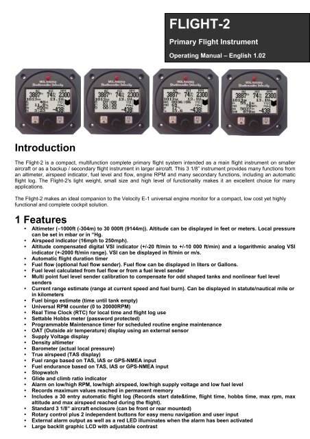
FLIGHT-2<br />
Primary <strong>Flight</strong> Instrument<br />
Operating Manual – English 1.02<br />
Introduction<br />
The <strong>Flight</strong>-2 is a compact, multifunction complete primary flight system intended as a main flight instrument on smaller<br />
aircraft or as a backup / secondary flight instrument in larger aircraft. This 3 1/8” instrument provides many functions from<br />
an altimeter, airspeed indicator, fuel level and flow, engine RPM and many secondary functions, including an automatic<br />
flight log. The <strong>Flight</strong>-2's light weight, small size and high level of functionality makes it an excellent choice for many<br />
applications.<br />
The <strong>Flight</strong>-2 makes an ideal companion to the Velocity E-1 universal engine monitor for a compact, low cost yet highly<br />
functional and complete cockpit solution.<br />
1 Features<br />
• Altimeter (–1000ft (-304m) to 30 000ft (9144m)). Altitude can be displayed in feet or meters. Local pressure<br />
can be set in mbar or in “Hg.<br />
• Airspeed indicator (16mph to 250mph).<br />
• Altitude compensated digital VSI indicator (+/-20 ft/min to +/-10 000 ft/min) and a logarithmic analog VSI<br />
indicator (+-2000 ft/min range). VSI can be displayed in ft/min or m/s.<br />
• Automatic flight duration timer<br />
• Fuel flow (optional fuel flow sender). Fuel flow can be displayed in liters or Gallons.<br />
• Fuel level calculated from fuel flow or from a fuel level sender<br />
• Multi point fuel level sender calibration to compensate for odd shaped tanks and nonlinear fuel level<br />
senders<br />
• Current range estimate (range at current speed and fuel burn). Can be displayed in statute/nautical mile or<br />
in kilometers<br />
• Fuel bingo estimate (time until tank empty)<br />
• Universal RPM counter (0 to 20000RPM)<br />
• Real Time Clock (RTC) for local time and flight log use<br />
• Settable Hobbs meter (password protected)<br />
• Programmable Maintenance timer for scheduled routine engine maintenance<br />
• OAT (Outside air temperature) display using an external sensor<br />
• Supply Voltage display<br />
• Density altimeter<br />
• Barometer (actual local pressure)<br />
• True airspeed (TAS display)<br />
• Fuel range based on TAS, IAS or GPS-NMEA input<br />
• Fuel endurance based on TAS, IAS or GPS-NMEA input<br />
• Stopwatch<br />
• Glide and climb ratio indicator<br />
• Alarm on low/high RPM, low/high airspeed, low/high supply voltage and low fuel level<br />
• Records maximum values reached in permanent memory<br />
• Includes a 30 entry automatic flight log (Records start date&time, flight time, hobbs time, max rpm, max<br />
altitude and max airspeed reached during the flight).<br />
• Standard 3 1/8” aircraft enclosure (can be front or rear mounted)<br />
• Rotary control plus 2 independent buttons for easy menu navigation and user input<br />
• External alarm output as well as a red LED illuminates when the alarm has been activated<br />
• Large backlit graphic LCD with adjustable contrast
FLIGHT-2 Operating Manual Page 2<br />
• Wide input supply voltage range of 8 to 30V DC with built in voltage reversal and over voltage protection<br />
for harsh electrical environments<br />
• Light weight design<br />
• 1 year limited warranty<br />
2 FLIGHT-2 Layout<br />
LED Alarm:<br />
The red LED will illuminate if any of the<br />
alarm conditions have been exceeded<br />
Pressure Ports:<br />
Pressure ports connect to<br />
static and pitot tubes<br />
Up/F1 Button:<br />
Up button in menu system<br />
Auxiliary flight information<br />
page toggle in normal mode<br />
Harness:<br />
Harness connects<br />
to power and signals<br />
Down/F2 Button:<br />
Down button in menu system<br />
Various functions in normal mode.<br />
See Auxiliary flight information<br />
displays below.<br />
Rotary Control (Up/Down) & Enter Button:<br />
Press the rotary control during normal mode to access the menu system.<br />
Rotate anti/clockwise for up/down menu scrolling. During normal mode rotating the rotary<br />
control will adjust the local pressure setting. Local pressure can be set in either mB or in “Hg.<br />
3 Main Display<br />
The bottom left of the main display is arranged in four auxiliary flight information displays.<br />
Active flight indicator<br />
Altimeter<br />
Airspeed indicator<br />
Engine RPM display<br />
Local pressure setting<br />
(QNH)<br />
Supply Voltage<br />
Auxiliary flight information<br />
Displays (4 displaypages)<br />
Digital VSI<br />
Analog VSI
FLIGHT-2 Operating Manual Page 3<br />
3.1 Auxiliary flight information display 1<br />
This page displays all the fuel related information. Fuel level, flow, range and endurance is shown.<br />
3.1.1 Enter starting level of the fuel tank<br />
Press the F2 key during the auxiliary flight information display 1 to manually<br />
enter your current fuel level after fueling or defueling your aircraft. This function<br />
is only available if you have selected calculated fuel level. Press the F2 key<br />
again as a “quick fill button” to the full level.<br />
Note: It is good airmanship to take into account a “silent” fuel reserve. For<br />
example, if you have a 50 liter tank and you fill it, enter 40 or 45 liters as<br />
your available fuel.<br />
3.2 Auxiliary flight information display 2<br />
This page displays the RTC, flight time and stopwatch.<br />
Real Time Clock<br />
Time of day is often displayed as UTC or Greenwich time as it required by ATC.<br />
<strong>Flight</strong> time<br />
The flight time is automatically reset to zero when a new flight is started (manual or automatic flight detection).<br />
Stop Watch<br />
Press the F2 key to start/stop the stopwatch. Hold the F2 key for 3 seconds to reset the stop watch to zero. The<br />
stopwatch icon will flash when the stopwatch is running.
FLIGHT-2 Operating Manual Page 4<br />
3.3 Auxiliary flight information display 3<br />
Hobbs Timer<br />
The <strong>Flight</strong>-2 contains a password protected hobbs timer. The Hobbs time can be set to the current known engine time in<br />
the menu system.<br />
Maintenance Timer<br />
This timer is set in engine hours and it will count down to zero when the engine RPM is greater then the Hobbs RPM limit.<br />
A good use for this function is to set the hours until your next spark plug change or engine inspection. See the<br />
maintenance timer section below for more details.<br />
OAT<br />
Outside air temperature can be measured using the external temperature probe.<br />
Glide Ratio<br />
Glide ratio can be measured up to 1:99. Glide ratio is measured as a ratio between forward movement of the aircraft vs.<br />
vertical sink rate. Please note that the forward movement of the aircraft is not synonymous with horizontal forward<br />
movement relative to the earth surface but is a function of airspeed.<br />
Climb Ratio<br />
Climb ratio can be measured up to 1:99. Climb ratio is measured as a ratio between forward movement of the aircraft vs.<br />
vertical climb rate. Please note that the forward movement of the aircraft is not synonymous with horizontal forward<br />
movement relative to the earth surface but is a function of airspeed.<br />
3.3.1 Start/Stop <strong>Flight</strong> Display<br />
Press the F2 key during the auxiliary flight information display 3 to manually start/stop a flight. This key is only active if the<br />
FLIGHT-2 is setup to select the manual flight option under the “FLIGHT LOG” setup menu.
FLIGHT-2 Operating Manual Page 5<br />
3.4 Auxiliary flight information display 4<br />
Distance through the air trip counter<br />
Air distance can be displayed either in kilometers, miles or nautical miles.<br />
Air distance is calculated taking in to account true airspeed and time since take-off. The FLIGHT-2 can be setup to either<br />
automatically reset air distance to zero at the beginning of a flight or you can manually decide when you want to reset air<br />
distance to zero.<br />
True Airspeed (TAS)<br />
TAS is used for most internal calculations where air distance is of importance.<br />
What is TAS and how is it calculated ?<br />
TAS is indicated airspeed (ASI) compensated for altitude and temperature. Often pilots ignore the effect of temperature<br />
and only take altitude into account when converting ASI to TAS. For practical purposes this is quite accurate and gives a<br />
good reflection on your true airspeed. Keeping in mind that ASI measurement is subject to errors caused by airflow<br />
around your aircraft, there seems little point in taking this calculation to absolute resolution.<br />
Again, we have decided to use a formula often used by pilots. This way the instrument reading will agree with what pilots<br />
are used to.<br />
Based on Worthingtons 13th edition page 349:<br />
Add 1.75% of IAS per 1000 ft (304.9 m) increase in altitude above sea level.<br />
We assume here that IAS = RAS (rectified air speed).<br />
Density Altitude<br />
Density altitude is a perceived altitude that pertains to your current altitude and temperature (and to a lessor extent on<br />
your current moisture content of the air). Density altitude is relevant for performance calculations of your aircraft. Density<br />
altitude affects the performance of your engine, propeller and airfoils. The most noticeable affects of density altitude are<br />
length of take-off and landing runs and the ability of your aircraft to carry weight. There are several methods to calculate<br />
density altitude, all result in readings that are very close to each other. We decided to implement a popular formula that is<br />
often used by pilots to calculate density altitude at their location.<br />
Da = Density altitude<br />
Pa = Pressure altitude<br />
T = ambient temperature in degrees C<br />
Da = Pa+118.6 * (T+0.85)<br />
Barometer<br />
Ambient pressure can be displayed in either millibar or Inches of Mercury (Inch/Hg). The setup for QNH will determine<br />
which.
FLIGHT-2 Operating Manual Page 6<br />
3.4.1 Reset Air Distance Trip Counter Display<br />
This display can be accessed by pressing the F2 key during the auxiliary flight information display 4. Pressing the F1 key<br />
will reset the air distance trip counter to zero. Pressing any other key will cause the FLIGHT-2 to resume to the normal<br />
display mode. The air distance trip counter can still be reset manually even if the pilot selects the automatic resetting of<br />
the air distance trip counter.<br />
Note: The air distance trip counter measures distance flown through the air. This is not the same as<br />
distance flown over the ground unless you are flying at sea level at zero wind speed. The air<br />
distance shown is subject to under reading at altitude due to decreased air density.<br />
4 Maintenance Timer<br />
The purpose of this function is to assist you in determining remaining hours until maintenance will be required. It is not<br />
intended as a replacement for the aircraft's maintenance log. It is therefore important that the aircraft's maintenance log<br />
be maintained in the normal manner. You should further use your own discretion in performing maintenance earlier than<br />
indicated should any aircraft performance problems arise.<br />
A maximum of 999 hours can be entered as a maintenance interval. The FLIGHT-2 will deduct actual engine running time<br />
from the maintenance interval hours as set and will display the reminder message on startup when zero hours are<br />
remaining. The reminder message will automatically disappear after 5 seconds or if the pilot presses any key. Engine<br />
running time for the purpose of the maintenance timer is defined as the run time where the engine RPM is greater than<br />
the preset RPM for the Hobbs meter.
FLIGHT-2 Operating Manual Page 7<br />
5 Menu System<br />
Pressing the rotary control button during the normal display mode will cause the FLIGHT-2 to enter the menu system. Use<br />
the up/down keys or the rotary control to navigate through the menu system.<br />
5.1 Exit Menu<br />
Pressing the rotary control on this menu item will cause the FLIGHT-2 to exit the menu system.<br />
All changes made during navigation of the menu system will be saved in non-volatile memory on<br />
exiting the menu system. If you remove power before exiting the menu the instrument will not<br />
save any changes.<br />
5.2 Maximum Values<br />
To avoid false recordings, the maximum values function is only activated 10 seconds after the<br />
instrument has powered up.
FLIGHT-2 Operating Manual Page 8<br />
Move the highlight over the “DONE” menu item and press the rotary button to return to the main<br />
menu.<br />
Move the highlight over this menu item and press the rotary button to reset the maximum values<br />
to the current values.<br />
5.3 <strong>Flight</strong> Log<br />
The FLIGHT-2 uses the following algorithm to determine if a flight is in progress (Detect Mode): If<br />
airspeed is greater than the preset flight take off airspeed for a duration of 60 seconds or more, a<br />
flight is started with a logbook entry. The flight ends if airspeed falls below the preset flight takeoff<br />
airspeed for 30 seconds. During a flight the logbook cannot be viewed.<br />
The above algorithm ensures that touch-and-goes will not result in the end of a flight and a logbook entry. Should the<br />
instrument be switched off during a flight, this will end the flight and the log will reflect the time until the instrument was<br />
switched off. Should the instrument be switched on again during a flight, a new flight will start for logging purposes.<br />
Move the highlight over the “DONE” menu item and press the rotary button to return to the main<br />
menu<br />
Select this function to view the flight log. The instrument will maintain a<br />
log of your last 30 flights. Each log entry contains date and time of<br />
your take-off, duration of the flight, maximum altitude,rpm and airspeed<br />
reached and also the reading of your engine Hobbs meter at the end of<br />
the flight.<br />
Use the up/down keys or the rotary control to navigate through the log.<br />
Note: You cannot select this function while a flight is in progress.<br />
Pressing the F1 key will erase all the flight log entries<br />
Select if you would like the hour to be displayed in decimal fractions (0-99) or minutes (0-59).<br />
This setting influences the current flight time display and the flight log.<br />
Select whether you want the FLIGHT-2 to automatically detect a flight or whether the pilot must<br />
press the F2 key to start/stop a flight.<br />
This menu option is only shown if the “detect” flight mode is selected. Enter the airspeed that you<br />
want to start a flight log.
FLIGHT-2 Operating Manual Page 9<br />
5.4 Fuel Total<br />
This totalizers the amount of fuel burn since the last time the accumulator was reset to zero.<br />
Move the highlight over the “DONE” menu item and press the rotary control to return to the main<br />
menu.<br />
Select this menu option to reset the fuel totalizer to zero.<br />
5.5 Display Setup<br />
Move the highlight over the “DONE” menu item and press the rotary button to return to the main<br />
menu<br />
Select this menu option to adjust the display contrast<br />
Select this menu option to turn the backlight on or off<br />
Select this option to set the date and time<br />
Select whether you want the OAT to be displayed in degrees Fahrenheit (ºF) or in degrees<br />
Celcius (ºC)
FLIGHT-2 Operating Manual Page 10<br />
5.6 Hobbs Meter<br />
Move the highlight over the “DONE” menu option and press the rotary button to return to the<br />
main menu.<br />
Enter the RPM limit in which the Hobbs meter/Maintenance timer must start counting.<br />
This function allows you to set the engine Hobbs meter to any value.<br />
Typically, you would use this function to set the Hobbs meter to the<br />
current known engine time. Use the up/down or the rotary control to<br />
change the value. Press the rotary control to accept and exit the menu<br />
option. If the Hobbs code is set to another value beside zero, then the<br />
pilot will be prompted to enter the Hobbs access code before allowing<br />
him to change the Hobbs time. This feature is useful for charted and<br />
flying school planes.<br />
This function allows you to set an engine maintenance timer. This timer<br />
is set in engine hours and it will count down to zero when the engine<br />
RPM is greater then the Hobbs RPM limit. A good use for this function is<br />
to set the hours until your next spark plug change or engine inspection.<br />
Use the up/down or the rotary control to change the value. Press the<br />
rotary control to accept and exit the menu option.<br />
Select if you would like the hour to be displayed in decimal fractions (0-99) or minutes (0-59).<br />
This setting influences the current flight time display and the flight log.<br />
This menu option allows you to change the Hobbs access code. You will first be prompted to<br />
enter the current code followed by entering in a new code followed by re-entering the new code.<br />
If the new code and the re-entered code is the same, then the Hobbs access code will be<br />
changed. Default code is 0000.
FLIGHT-2 Operating Manual Page 11<br />
5.7 Altitude Setup<br />
All altitude related parameters can be setup here.<br />
Move the highlight over the “DONE” menu item and press the rotary button to return to the main<br />
menu.<br />
Select if you want your altitude readout in feet (ft) or meters (m).<br />
Select if you want your local pressure readout in millibars (mB) or inches of mercury (“Hg).<br />
5.8 Airspeed Setup<br />
All the airspeed parameters can be setup here<br />
Move the highlight over this menu option and press the rotary button to return to the main menu<br />
This setup allows your instrument to measure the zero airspeed reading<br />
of the airspeed sensor and set a calibration value internally for this. This<br />
is equivalent to some mechanical airspeed indicators that have an<br />
adjustment to set the needle to zero when the aircraft is not moving. You<br />
would use this function occasionally if you see an airspeed reading when<br />
the aircraft is at rest. This may be caused by aging of the built in<br />
pressure sensor or related electronics. When this function is performed<br />
make sure that there is no air flow into the pitot tube as this would result<br />
in an incorrect internal calibration.<br />
Pressing the F1 key will zero the airspeed sensor.<br />
Select whether you want the low air speed alarm to be turned on or off. The low airspeed alarm is<br />
only activated once a flight has started.<br />
Enter the low airspeed set-point for when the alarm must activate. Any speed below this value<br />
will activate the alarm.<br />
Select whether you want the high air speed alarm to be turned on or off. Any airspeed above this<br />
value will activate the alarm.
FLIGHT-2 Operating Manual Page 12<br />
Enter the high airspeed set-point for when the alarm must activate. Any speed above this value<br />
will activate the alarm.<br />
Select your preferred units. You can select statute miles, kilometers or nautical miles. According<br />
to this selection your airspeed will be indicated in mph, km/h or knots.<br />
This function can be used to select the signal filter time constant. Selections are “fast” or “slow”.<br />
This selection influences the rate at which your ASI can change its reading. If you have an<br />
installation that suffers from strong turbulence at the pitot tube, select “slow”. If you have a very<br />
clean airflow in front of the pilot tube you can select “fast” which will give you a faster response to<br />
airspeed changes.<br />
Select if you want the air-distance counter to reset automatically at the start of a flight or if you<br />
want to reset it manually only.<br />
Note: You can reset the air distance counter at any time regardless of this setting.<br />
5.9 VSI (Vertical Speed Indicator) Setup<br />
All VSI related parameters can be setup here.<br />
Move the highlight over the “DONE” menu item and press the rotary button to return to the main<br />
menu.<br />
This function is used to set your VSI to read exactly 0ft/min. This is similar to setting the needle<br />
on a mechanical VSI to point to zero by turning the adjustment knob on such a VSI. The<br />
electronic VSI generally has much less drift compared to a mechanical VSI and this function will<br />
only be used very occasionally. Ensure that you perform this function when no pressure changes<br />
due to wind or other reasons are occurring.<br />
Select if you want your VSI readout in feet/minute (ft/m) or meters/second (m/s).<br />
Note: meters/second will be shown with two decimals, example: “1.23”.<br />
This is a function that is used to calibrate your VSI to read exact rates of climb or decent. This<br />
function works as a percentage of initial reading. The default setting for this function is 100%.<br />
Increasing this value increases the VSI reading and decreasing the value decreases the reading.<br />
Suggested VSI calibration method<br />
After you have installed the instrument, perform a calibration flight. This should be done in very calm conditions.<br />
Turbulence and thermal activity will make accurate calibration impossible. Many areas have ideal conditions during early<br />
mornings or late afternoons. Place the instrument in “feet” unit mode for ease of calibration. Take your aircraft to a few<br />
thousand feet above ground and start a glide with a low power setting. Take a stopwatch and when the glide is stable<br />
(stable VSI reading) start the stopwatch. Take note of your altimeter reading at the same time. Continue the stable glide<br />
for one minute exactly. After the minute has finished, take another reading of your altimeter.
FLIGHT-2 Operating Manual Page 13<br />
Example:<br />
VSI reading during stable glide: -400 ft/min<br />
Start altitude: 2500 ft.<br />
End altitude: 2050 ft.<br />
In the above example the VSI is under reading by about 12%. Set your VSI calibration to 112% to cancel out the error.<br />
5.10 RPM Setup<br />
All the RPM related settings can be setup here.<br />
Move the highlight over the “DONE” menu option and press the rotary button to return to the<br />
main menu.<br />
Select if you want the RPM display to be shown or not.<br />
Select whether you want the RPM low alarm to be turned on or off.<br />
Enter the RPM alarm activation threshold. Any RPM value below this value will activate the<br />
alarm.<br />
Select whether you want the RPM high alarm to be turned on or off.<br />
Enter the RPM alarm activation threshold. Any RPM value above this value will activate the<br />
alarm.<br />
Enter the number of pulses per RPM. For engines with an uneven number of cylinders like three<br />
cylinder four stroke engines you can enter values containing fractions (usually 1.5 in this<br />
example). Most four stroke engines would generate one pulse for every two revolutions per<br />
cylinder. A four cylinder automotive four stroke engine would thus generate 2 pulses per<br />
revolution. A typical Rotax DCDI two stroke engine would generate 6 pulses per revolution. The<br />
well known Rotax 912/914 engine generates one pulse per revolution.<br />
PULSE: The FLIGHT-2 counts pulses from the engine for ½ second period (fast frequency input).<br />
TIME: The FLIGHT-2 uses the time between pulses to calculate revs (slow frequency input).<br />
Typical setups:<br />
Rotax 503,582 DCDI – Pulse (Fast frequency) (6 pulses per revolution)<br />
Rotax 503 single ignition, Rotax 912/914 – Time (Slow frequency) (one pulse per revolution)<br />
Gyro Rotor RPM with gear tooth sensor - Pulse (Fast frequency) (about 100 pulses per revolution)<br />
Gyro Rotor RPM with single hall-effect sensor – Time (Slow frequency) (one pulse per revolution)<br />
Helicopter Rotor RPM with single hall-effect sensor – Time (Slow frequency) (one pulse per revolution)
FLIGHT-2 Operating Manual Page 14<br />
The FLIGHT-2 unit contains a digital filter. This filter is used to achieve a higher resolution of the<br />
digital rev counter than is available in ordinary operation. In digital rev counters, resolution is<br />
largely dependent on the amount of time given to measure RPM. The more time that is available,<br />
the higher the resolution will be. However, on the downside of this, the more sluggish the display<br />
will react to changes in engine settings. Resolution with the FLIGHT-2 is dependent on the<br />
number of pulses per rev and the type of measurement method you have selected (Pulse Pulse/Time). The update rate<br />
for the measurement is a fixed, fast 0.5 seconds. The digital filter is activated whenever input revs are fairly constant and<br />
this results in a very high resolution of the digital RPM display in a short time span. The filter needs to be setup for the<br />
expected base resolution. This can be between 10 and 30 RPM for most setups. The filter has the following settings:<br />
10,20,30,40,50,60,70,80,90,100 – The filter factor can be set to any of these values independent of your scale selection.<br />
Choose a filter setting that results in a smooth, high resolution RPM display. A filter setting too low for your setup will<br />
result in a “jumpy” display. RPM display will change at your base resolution and no smoothing will happen. Choose the<br />
lowest setting that will result in a smooth display for greatest sensitivity of the reading.<br />
5.11 Fuel Setup<br />
All the Fuel related settings can be setup here.<br />
Move the highlight over the “DONE” menu item and press the rotary control to return to the main<br />
menu.<br />
Select your desired units for distance and fuel quantity. The following options are available:<br />
L/sm: Liters and statute miles<br />
G/sm: U.S. Gallons and statute miles<br />
L/nm: Liters and nautical miles<br />
G/nm: U.S. Gallons and nautical miles<br />
L/km: Liters and kilometers<br />
G/km: U.S. Gallons and kilometers<br />
Select which speed will be used for range based calulations. You can select beteween “TAS”<br />
(True airspeed), "IAS" (Indicated airspeed) or “GPS-NMEA” (obtained from a RS232 NMEA<br />
enabled GPS receiver) .<br />
Select the Baud rate of your NMEA GPS receiver.<br />
Select if there is a fuel flow sender connected to the FLIGHT-2's fuel flow input.<br />
The K-Factor is the number of pulses generated by the fuel flow sender for one liter of fuel. The<br />
dual range fuel flow sender supplied by <strong>MGL</strong> <strong>Avionics</strong> has a K-Factor of 7000 in the low flow<br />
mode (jet installed) and 1330 for the high flow mode (no jet installed). The Flowscan 201A-6 has<br />
a K-Factor of 8454. You can use the K-Factor to calibrate your fuel flow sender. See the<br />
installation section for more details on how to calibrate and install the fuel flow sender.<br />
Select if the fuel tank has a physical fuel level sender connected to it or if the FLIGHT-2 must use<br />
a calculation based virtual fuel tank. If you do not want any fuel level information then set this<br />
parameter to off.
FLIGHT-2 Operating Manual Page 15<br />
Enter the size of the fuel tank in your system. It is recommended to choose a size that is slightly<br />
less than actual size so you can compensate for sender inaccuracies and give you a measure of<br />
reserve fuel.<br />
See section 5.10.1 on how to calibrate the fuel level sender.<br />
Select the damping factor for the fuel level. A selection of none, low, med or high can be made.<br />
Select whether to turn the fuel tank level alarm on or off.<br />
Enter your desired minimum fuel value that you would like to trigger the fuel low alarm. The fuel<br />
low alarm will result in the flashing of the fuel level display and remaining fuel readout. You can<br />
also connect a warning lamp to the external alarm output (see installation diagram).<br />
5.11.1 Calibrating the fuel level sender<br />
The fuel level sender needs to be calibrated before it can be used with this system. The<br />
calibration allows the system to learn the shape of your tank as well as any errors your fuel<br />
level sender or installation has.<br />
Regardless of your use of a fuel flow sender, you can install a fuel level sender into your fuel tank. These level senders<br />
are inexpensive and are available as after market replacement fittings from a car spares outlet. We recommend the<br />
senders available from VDO.<br />
Be aware that some makes of cheap level senders can prove troublesome, as the lever arms tend to be sticky.<br />
This prevents the floats from floating on the surface of the fuel at all times. As a consequence, this will lead to<br />
incorrect fuel level indication.<br />
Adjusting calibration points automatically<br />
Select “SENDER” for the mode menu item. Once you have installed a fuel level sender into your tank, make sure the float<br />
can travel all the way from empty to full position without hindrance of any kind. The calibration procedure should be<br />
carried out with your aircraft in flight attitude. This means you need to lift the tail if you have a tail-dragger or lift the nose<br />
wheel if you have a weightshift trike.<br />
Calibration procedure<br />
• Start the calibration procedure with an empty tank.<br />
• Add five liters of fuel (our reserve quantity) using a suitable measure. Make sure the measure is suitably<br />
accurate. This is now the “level sender reading at 0 Lt” position. Move the highlight to this position and wait until<br />
the sender reading has stabilized (You will see the sender reading at the top line). This could take up to a minute<br />
so have patience.<br />
ENSURE THAT THE FLOAT IS NOT SUBMERGED AND IS FLOATING ON TOP OF THE FUEL LEVEL.<br />
Should this number not react to changes of your level sender position, then you have a problem. Please check<br />
your wiring according to the installation section of this manual. You should expect the number to change in the
FLIGHT-2 Operating Manual Page 16<br />
region of at least 20 to 60 counts per calibration position. If the number does not change with fuel level or only<br />
changes a very small amount – check your installation. Something is not right!<br />
• If you see the number changing then everything is well. Once it has stabilized and the highlight is on the 0 L<br />
position, press the rotary control to transfer the reading from the sender to the calibration point.<br />
• Now you are ready for the next step. Add the required amount of fuel to get to the next level (In our case 9 Lt –<br />
this is 20% tank capacity). Once done, wait for the reading to stabilize and press the rotary control again after you<br />
have moved the highlight to the “9 L” position.<br />
• Proceed in a similar manner until you have reached the last calibration position at 100% tank capacity.<br />
You are done!<br />
To finish your calibration, exit the calibration function by moving the highlight over the “DONE” menu item and<br />
press the rotary control.<br />
The instrument uses the 6 calibration points to work out a correction curve that takes into account the tolerances of your<br />
fuel level sender and the shape of your fuel tank. This results in an incredibly accurate and usable fuel level display that<br />
far exceeds that available from ordinary dial type gauges.<br />
Adjusting calibration points manually<br />
You may want to set individual calibration points manually. For example you may find that your<br />
fuel level is over reading at a specific fuel level. Correcting the tank level reading for this area can<br />
be simply done by adjusting the calibration point. You can do this by moving the float level with<br />
your hands to the desired position and then performing the calibration as outlined above, or<br />
you can use the manual option.<br />
Select “MANUAL” for the mode menu item. Then highlight the point you want to change manually and press the rotary<br />
control. Use the up or down keys or the rotary control to adjust the value. Press the rotary control when done.<br />
Note: The calibration positions may be edited by using the up and down keys. This allows you, in theory, to copy<br />
calibration settings from one instrument to another. We however recommend that you do go though the calibration<br />
procedure even if the two aircraft are identical in all respects. Tolerances do exist and the calibration cancels these out.<br />
Accurate fuel level displays are a vital safety factor for an aircraft and a very useful feature for peace of mind during cross<br />
county flights.<br />
Notes on Slope error<br />
Sender value is a value determined by the FLIGHT-2. It is used to calculate fuel level, fuel<br />
endurance estimate and current range estimate. The fuel tank setup sender value can either<br />
increase in value as fuel is added or decrease in value if fuel is added. This is dependent on the<br />
type of fuel level sender used. However should the second reading be larger than the first<br />
reading all readings will have to be larger than the previous readings. Likewise should the second<br />
reading be smaller than the first reading all readings will have to be smaller than the previous<br />
reading.<br />
If this is not the case the wording "Slope error" will be displayed. This could happen when fuel was removed instead of<br />
added between steps, no fuel was added between steps or when the fuel level sender was moved in the wrong direction<br />
e.g. moving the fuel level sender manually when it is not inserted in to the fuel tank. Determine the cause of the error if<br />
you should get a slope error message. If you do not know the cause of your error it is best to start from scratch. It should<br />
be remembered that accuracy in the fuel tank calibration is extremely important to enable your FLIGHT-2 to display the<br />
correct data.<br />
5.12 Voltage Setup<br />
Move the highlight over this menu item and press the rotary button to return to the main menu.
FLIGHT-2 Operating Manual Page 17<br />
Select whether you want the voltage low alarm to be turned on or off.<br />
Enter the low voltage set-point for when the alarm must be activated. Any voltage below this<br />
value will activate the alarm.<br />
Select whether you want the voltage high alarm to be turned on or off.<br />
Enter the high voltage set-point for when the alarm must be activated. Any voltage above this<br />
value will activate the alarm.<br />
6 Loading factory default settings<br />
Pressing and holding the F1 and F2 simultaneously on power up will cause the FLIGHT-2 to load preprogrammed factory<br />
default settings. The following screen will be displayed:<br />
7 Operating the alarms<br />
If the alarm is activated, the corresponding item on the display will flash. At the same time the externally available alarm<br />
switch will close. The switch will remain closed until any button is pressed to acknowledge the alarm or until the<br />
condition(s) that activated the alarm no longer exist. The alarm output can be used to switch an external alarm indicator.<br />
The external alarm switch is an open collector transistor switch to ground with a maximum rating of 0.5A DC. It is possible<br />
to wire the alarm contacts of several Stratomaster instruments in parallel should this be desired. To avoid false activation<br />
of the alarms, the alarm function is only active 10 seconds after the instrument has powered up.<br />
8 Cleaning<br />
The unit should not be cleaned with any abrasive substances. The screen is very sensitive to certain cleaning materials<br />
and should only be cleaned using a clean, damp cloth.<br />
Warning: The FLIGHT-2 is not waterproof. Serious damage could occur if the unit is exposed to<br />
water and/or spray jets.
FLIGHT-2 Operating Manual Page 18<br />
9 FLIGHT-2 Specifications<br />
Operating Temperature Range<br />
Storage Temperature Range<br />
Humidity<br />
Power Supply<br />
Current Consumption<br />
Display<br />
Dimensions<br />
ADC<br />
Enclosure<br />
Weight<br />
Alarm contact current rating<br />
Non-volatile memory storage<br />
-10ºC to 50ºC (14ºF to 122ºF)<br />
-20ºC to 80ºC (-4ºF to 176ºF)<br />
FLIGHT-2 Operating Manual Page 19<br />
10 Installation<br />
10.1 Altimeter Installation<br />
Connect the static port to a suitable static air pressure line. If you have a slow aircraft or an aircraft were the internal cabin<br />
pressure does not change during flight and is equivalent to the outside air pressure you may find that it is not required to<br />
connect a static port.<br />
For installations in typical ultralight aircraft pods, be aware of possible pressure changes inside the pod during flight<br />
caused by ram air or suction effects. This may lead to a false indication of altitude and airspeed. Often these effects are<br />
dependent on the current angle of attack of the airflow around your pod. You will need to install a suitable static port in<br />
these cases.<br />
Static ports are usually mounted at a strategic position on the rear side of the aircraft fuselage for faster, pressurized<br />
aircraft.<br />
10.2 Airspeed Installation<br />
Connect your pitot tube to the “pressure port”. Pitot tubes are found in a large variety at your aircraft parts shop, in mail<br />
order catalogs or you can make your own. Contrary to popular belief, pitot tubes are not carefully designed and calibrated,<br />
but are simple orifices or tubes that get pointed in the direction that you are flying. The forward movement of the aircraft<br />
causes air to dam inside the pitot tube. This increases the pressure inside the tube.<br />
Suitable pitot tubes can be made from a short piece of hollow aluminium or copper piping. Length and diameter are not<br />
important. Ensure that the front of the pitot tube has a suitable chamfer if you use thick walled tubing or you may<br />
introduce a speed reading error if you have a faster aircraft.<br />
Example cross-section of thick walled pitot tube.<br />
Suitable connection hose for both pitot tube and static port can be obtained from a hardware store or even a pet shop.<br />
Good quality tubing is often used for fish tanks and it has just the right diameter. Please note that this kind of tubing is not<br />
advised for pressurized aircraft. In this case you would need to obtain aircraft grade tubing of suitable diameter. You<br />
would also have to use hose clamps to fasten the hose onto the FLIGHT-2 pitot and static ports. The FLIGHT-2 allows<br />
you to calibrate the airspeed reading. This is done in the “Calibrate” menu item. The main reason for this is to be able to<br />
remove errors introduced due to the airflow around your aircraft which may have an effect of your pitot tube pressure.<br />
10.3 Fuel flow sender installation<br />
The fuel flow sender allows the FLIGHT-2 to provide instantaneous readouts of hourly fuel usage, and both time and<br />
distance estimates on remaining fuel in flight. You can also verify the performance of your fuel pump during the pretakeoff<br />
engine run up – a very valuable check! Further, it is possible to set up the instruments to calculate fuel remaining<br />
by subtracting fuel used from a value entered when you filled your tank(s). In this case you may omit the installation of the<br />
optional fuel level sender. Please note that the installation of the fuel Flow sender should be done in such a fashion that<br />
dirt or debris from the fuel tank cannot lodge inside the flow sender. These will not block you fuel flow but may lead to the<br />
impeller inside the sender jamming. It is usually sufficient to mount the flow sender AFTER the fuel filter but before the<br />
fuel pump. It is a good idea to provide a small reservoir such as a primer bulb between the flow sender and the fuel pump.
FLIGHT-2 Operating Manual Page 20<br />
As indicated in the recommended installation drawing, it can be of advantage to install the flow sender in such a fashion<br />
that the inlet points slightly down and the outlet points slightly up. This prevents vapor from forming a bubble inside the<br />
flow sender. We strongly recommend mounting the flow sender in such a fashion that the impeller rests on only one<br />
bearing. This is achieved if you mount the sender such that the surface with the arrow faces upwards. Mounting the<br />
sender like this results in the best performance at low flow rates as only very little friction is present. The flow sender is<br />
delivered with a small jet that can be installed in the flow sender inlet. Installation of this jet is recommended for engines<br />
with fuel flow rates lower than about 30 liters per hour. This would apply to most small two and four stroke engines. The<br />
FLIGHT-2 is shipped with the fuel flow sender calibration set for the jet installed. In a good installation you can expect<br />
about +/- 3% maximum flow reading error with this factor. You can calibrate the flow sender yourself to a higher degree of<br />
accuracy if you so desire.<br />
Recommended procedure to calibrate the fuel flow sender:<br />
Note: You must disable the fuel level sender if you have one installed, and enable the calculated fuel level sender.<br />
1. Fill your tank exactly to a known level (for example 50 liters).<br />
2. Set your fuel level to 50 liters.<br />
3. Fly your aircraft for a period that you know will use approximately 20 liters of fuel. The exact fuel burn is not<br />
important; just burn about 20 liters of your fuel. At the end of your flight the instrument should give you a reading<br />
of how much fuel you have left – the reading should be about 30 liters left.<br />
4. Now place your aircraft in exactly the same position that you used when you first filled the tank and refill the tank<br />
to 50 liters using a measuring jug. You should find that you need 20 liters of fuel to refill to 50 liters.<br />
5. If you find that the instrument under or over reads the fuel used, you should perform a simple adjustment of the<br />
fuel flow sender calibration factor.<br />
Example:<br />
Actual fuel used: 21.5 liters, FLIGHT-2 fuel burn calculated 29.7 liters left in the tank. This means the FLIGHT-2<br />
measured 50-29.7 = 20.3 liters. We are under reading by 1.2 liters.<br />
Default calibration factor in Fuel setup menu = 7000.<br />
Let the corrected calibration factor be X.<br />
X = (20.3 * 7000) / 21.5<br />
X = 6609.3<br />
The closest setting you can enter as factor is 6609. Enter it into the unit and you are done!<br />
Repeat the above procedure to verify that your flow sender is now reading correctly.<br />
Please note:<br />
Before you calibrate the flow sender ensure there are no problems with your installation. We find the senders are very<br />
accurate if everything is installed and working properly. If your fuel burn indication is out by a large amount you have a<br />
problem that you should not attempt to fix by fiddling with the calibration factor! Please ensure that no fuel vapor can be<br />
trapped inside the sender housing in the form of bubbles. Due to the low fuel flow rates the bubbles will prevent the tiny<br />
impeller from turning freely, you can verify the turning of the impeller. You should notice three dark spots that are just<br />
visible in the inside of the fuel flow sender. These are small magnets that are attached to the impeller. With fuel flowing<br />
you should see the magnets turning. The best defense against vapor bubbles is to install the flow sender in such a way<br />
that the bubbles can escape. The easiest way is to point the outlet slightly upwards and the inlet (with the jet) slightly<br />
downwards. Another possible problem is the fuel sender jet. When you install it, do not damage it. Use a drill bit of<br />
suitable diameter (5.5mm) to push the jet all the way, the opening of the jet must be just in front of the impeller.<br />
YOU NEED TO APPLY SOME FORCE TO INSERT THE JET ALL THE WAY (about 24mm). THE JET MUST BE<br />
LOCATED RIGHT IN FRONT OF THE IMPELLOR. YOU CANNOT PUSH THE JET TOO FAR.
FLIGHT-2 Operating Manual Page 21<br />
Using other Flow Senders<br />
It is quite possible to use flow senders other than the <strong>MGL</strong> <strong>Avionics</strong> fuel flow sender. In this case ensure that the sender<br />
outputs a 5V TTL square wave or a similar signal. The FLIGHT-2 interface electronics will adapt to a variety of different<br />
voltages and pulse shapes as it contains a Schmitt-trigger input stage. The calibration factor can be entered in a wide<br />
range making the unit particularly suited to other flow senders. The supply output terminal for the sender provides a<br />
positive, regulated 5 volt output. This may be used to power the flow sender provided the sender will not draw more than<br />
40 mA of current. Should your sender require a higher voltage or more current, you must supply the sender from a<br />
different power source. Exceeding the rating on the <strong>MGL</strong> <strong>Avionics</strong> fuel flow sender supply terminal can affect the<br />
operation on the unit negatively or even damage it. Some senders require a pull-up resistor to the 12V supply line. We<br />
find most installations of these senders require a 4K7 pull-up resistor.<br />
Recommended Calibration Factors for the <strong>MGL</strong> <strong>Avionics</strong> dual range flow sender:<br />
With jet installed = 7000. Recommended for flow rates below 30 liters/hour maximum<br />
Without jet installed = 1330. Recommended for flow rates above 30 liters/hour<br />
Please refer to the leaflet included with the flow sender for information on pressure drop versus flow rate, wetted materials<br />
etc.<br />
It is your responsibility to ensure that the flow sender used is compatible with the fuels you intend using. We<br />
have found the <strong>MGL</strong> <strong>Avionics</strong> fuel flow sender to be very compatible with automotive fuels used in South Africa,<br />
many of which contain methanol. 100LL AVGAS also appears not to harm the sender in any way. We have<br />
exposed a sender continuously to our automotive fuels for the duration of two years without any noticeable ill<br />
effect on the sender. However, despite this <strong>MGL</strong> <strong>Avionics</strong> or its appointed agents cannot assume responsibility<br />
for any incident or damage, even loss of life by whatsoever cause connected with the fuel flow sender or the<br />
FLIGHT-2 instrument. Usage of this or other senders is your own sole responsibility.<br />
If you do not agree with the above statement you must not use the fuel flow sender.<br />
Note to Pilots: (Even though this is the installation manual)<br />
You must always have a visual indication of the fuel level available, either by means of a sight glass, direct tank<br />
observation or a known, reliable secondary fuel level gauge. Fuel level indication by means of calculated fuel burn is<br />
subject to errors both by entering incorrect starting fuel levels as well as mechanical problems causing the flow sender<br />
impeller to turn too slowly, resulting in under reading fuel burn and thus over reading remaining fuel. As pilot in command<br />
of an aircraft it is your responsibility to ensure that you have sufficient fuel to reach your intended destination. Always<br />
ensure that you have a generous amount of reserve fuel and never use your reserve fuel except in an emergency if it is<br />
unavoidable.<br />
10.4 Floscan 201 fuel flow sender installation<br />
1. The inlet and outlet ports in series 201 flow transducers have ¼” NPT threads. Use only ¼” NPT hose or pipe<br />
fittings to match. When assembling fittings into the inlet and outlet ports DO NOT EXCEED a torque of 15 ft. lbs.<br />
(180 inch lbs.), or screw the fittings in more than 2 full turns past hand tight, WHICHEVER COMES FIRST.<br />
FloScan Instrument Co., Inc. will not be responsible for cracked castings caused by failure to use ¼” NPT fittings,<br />
over torquing the fittings, or assembling them beyond the specified depth.<br />
2. A screen or filter should be installed upstream of the flow transducer to screen out debris which could affect rotor<br />
movement or settle in the V-bearings. As turbulence upstream of the transducer affects its performance, there<br />
should be a reasonable length of straight line between the transducer inlet and the first valve, elbow, or other<br />
turbulence-producing device.<br />
3. Install the flow transducer with wire leads pointed UP to vent bubbles and insure that rotor is totally immersed in<br />
liquid. For maximum accuracy at low flow rates the transducer should be mounted on a horizontal surface.<br />
4. Power supply: 12 VDC at 100mA filtered and regulated.<br />
5. Series 200 flow transducers are designed to measure steady state flows. Indicated accuracies and pulse counts<br />
were obtained using heptane on a flow stand with rotary pumps and are reproducible in flow systems using rotary<br />
or gear pumps. Fuel systems with diaphragm fuel pumps and carburetors produce pulsating fuel flows. For<br />
accurate results on these systems consult the factory for the correct flow transducer/pulsation damper<br />
combination.
FLIGHT-2 Operating Manual Page 22<br />
Wiring the Floscan Flow Transducer<br />
The FLIGHT-2 unit measures the output from the transducer. A 5600 ohm (5k6) pull-up resistor is required. See wiring<br />
table and installation diagram below.<br />
The gallon per hour K-Factor for the 201A-6 transducer is approximately 32,000. The K-Factor of each sensor (at 16<br />
GPH), divided by 10, is written on a label attached to sensor. Multiply this number on the label by 10, which should give a<br />
value of approximately 32,000. The FLIGHT-2 requires a litre per hour K factor. Take the gallon per hour K factor, and<br />
divide it by 3.785 (which yields a K-Factor of approximately 8454).<br />
Floscan transducer wire color<br />
White<br />
Black<br />
Red<br />
FLIGHT-2 DB9 Terminal/Other Terminal<br />
Fuel flow sender (DB9 pin 8 – yellow)<br />
FLIGHT-2 ground (DB9 pin 1 – Black) / Aircraft<br />
ground / Engine block<br />
+12V DC Supply (Not supplied by the FLIGHT-2)<br />
Floscan connection diagram<br />
Model 201A-6 Model 201B-6 Model 201C-6<br />
Flow range: Gasoline 0.3 – 30 GPH 0.6 – 60 GPH 2.0 - 80 GPH<br />
Flow range: #2 Diesel 2.0 – 30 GPH 3.0 – 60 GPH 8.0 – 80 GPH<br />
Approximate K-Factor¹: Gasoline 32 000 28 000 – 31 000 24 000<br />
Approximate K-Factor¹: Diesel 33 000 28 000 25 000<br />
Pressure Drop: Gasoline 0.6psi @ 15 GPH 1.2psi @ 30 GPH 1.4psi @ 40 GPH<br />
2.4psi @ 30GPH 4.8psi @ 60GPH 5.8psi @ 80 GPH<br />
Pressure Drop: #2 Diesel 0.8psi @ 15GPH 1.5psi @ 30GPH 1.8psi @ 40GPH<br />
3.0psi @ 30GPH 6.0psi @ 60GPH 7.2psi @ 80GPH<br />
Repeatability between measurements 0.25% @ 16GPH 0.25% @ 16GPH 0.25% @ 16GPH<br />
Working pressure 200psi 200psi 200psi<br />
Temperature range -65º/100ºC -65º/100ºC -65º/100ºC<br />
Bearing life expectancy 10 000 hr min. 10 000 hr min. 10 000 hr min.
FLIGHT-2 Operating Manual Page 23<br />
Notes:<br />
1. Pulses/Gallon @ 16 GPH<br />
2. All flow transducers are tested and marked with K-factor at 16 GPH. Repeatability at 16 GPH is guaranteed to 0.25%.<br />
Transducers are available with calibrated K-factors at additional cost<br />
10.5 Fuel level sender installation<br />
The FLIGHT-2 permits the connection a standard automotive fuel level sender. These senders can be obtained at<br />
automotive spares outlets at reasonable cost. When you choose a float level sender, ensure that you select a model that<br />
is sturdy and promises reliable and long lifetime. In particular, select a model that does not have any metal parts that can<br />
rust. The FLIGHT-2 can interface to a large variety of these fuel level senders. It does not matter if the sender resistance<br />
increases or decreases with the fuel level as long as it changes. The calibration procedure outlined in the “Fuel Setup”<br />
section describes in great detail the procedure to follow.<br />
In essence, the calibration procedure will measure the resistance of the fuel level sender at various fuel levels and then<br />
work out the readings in between those known settings. Typical fuel level senders that can be used with the FLIGHT-2<br />
have resistance ranges in the region of 100 ohms to 500 ohms. Connect the flange of the sender to the negative supply<br />
(ground). You can connect capacitive senders as well. These generally come in two types: The first emulates a normal<br />
resistive probe and is simple to connect and use as a result. The second type has a voltage level output. These can be<br />
used if the voltage can be set to a range of about 0-5V. Higher voltage levels will result in the instrument assuming a<br />
problem.<br />
We recommend using VDO float based fuel level senders. Capacitive types can be used provided they have a voltage<br />
output not exceeding 5V. The level terminal has an internal 1K resistor pull-up to +5V. Please note that capacitive<br />
senders may exhibit large errors as they are very sensitive to the composition of the fuel used. We do not recommend<br />
using capacitive senders with automotive fuels for this reason.<br />
Safety Hazard! Please take note:<br />
Be careful when installing fuel level senders into fuel tanks. Ensure that the fuel tank is completely empty<br />
when you proceed with the installation. Ensure that the fuel tank is well ventilated and does not contain any<br />
fuel vapors – these are highly explosive when mixed with air. Ensure that at all times the ground<br />
connection (the connection of the fuel level sender mounting flange) is securely connected to the aircraft<br />
frame (in case of a metal frame) and to the negative terminal of the battery. In addition the negative<br />
terminal of the battery must at all times be connected to the supply ground terminal of the FLIGHT-2.<br />
Please note – this wiring is critical and must never break in flight. It would be possible to create electrical<br />
sparks in the fuel tank if your wiring is faulty or incorrect. The consequences of this can be imagined. This<br />
has nothing to do with the FLIGHT-2 itself but is a general hazard for any automotive fuel level sender<br />
installation. If you have no experience with electrical wiring, PLEASE delegate the task to a qualified<br />
automobile electrician or electronics technician. If you need to remove the FLIGHT-2, please first<br />
disconnect and secure the fuel level sender wire before disconnecting anything else.<br />
10.6 RPM Installation<br />
10.6.1 About RPM Measurements<br />
Generally, there are two different methods of measuring RPM. The FLIGHT-2 unit can be setup to perform either method.<br />
The first method involves counting pulses generated by some device in the engine or from a sensor in case of Rotor<br />
RPM. Pulses are counted over a period of time and the result is then used to calculate RPM. This method requires a high<br />
number of pulses and a short measurement interval. The FLIGHT-2 counts pulses for ½ second. This method is suitable<br />
for most two stroke engines such as produced by Rotax.<br />
Engines producing few pulses (perhaps only one pulse per revolution) and run at low revs, as well as slow turning rotors<br />
require a different method. Here the FLIGHT-2 can use the time it takes to generate only two pulses as bases for the<br />
RPM calculation. The particular method to be used and the number of pulses per revolution are entered as part of the<br />
FLIGHT-2 setup as given below.
FLIGHT-2 Operating Manual Page 24<br />
10.6.2 RPM Installation<br />
After you have connected the rev counter terminal to the signal source you need to set the number of pulses per<br />
revolution under the “RPM SETUP” menu. The calibration itself depends on your engine type and what kind of signal you<br />
are using. Typical sources are:<br />
• Magneto coils (suitable signal at the kill switch)<br />
• Primary (low voltage) side of ignition coil, at contact breaker or electronic ignition module<br />
• RPM counter output of electronic ignition systems (for example Bosch Motronic)<br />
• RPM pickup devices such as hall-effect sensors on flywheels etc.<br />
Installation of the FLIGHT-2 is quite straight forward in most cases. The drawing in section 10.8 shows a typical FLIGHT-2<br />
installation. Please see the engine connection diagrams for the RPM connection to the FLIGHT-2. The FLIGHT-2 input is<br />
quite universally usable. The rev counter input on the FLIGHT-2 can be used with signals from about 5Vpp to as much as<br />
100Vpp and the input is AC coupled for easy installation. A noise filter is included that results in the input ignoring any<br />
noise signals as long as this is below the detection threshold of about 2.5Vpp. The input impedance of the rev counter<br />
input is approximately 10Kohm. You can use series resistors as well as load resistors for applications that have unusual<br />
signals.<br />
For installations such as with the Rotax DCDI two-stroke engines, the rev counter input is simply connected to the grey<br />
rev counter wire from the engine. These engines produce six pulses per rev (set this up in the relevant menu item). Most<br />
engines produce 0.5, 1 or 2 pulses per revolution. This needs to be setup in the “RPM SETUP” menu item.<br />
Please note: The +5V supply line is unprotected and intended only for the supply of a hall-effect , optical<br />
or gear tooth sensors. Connecting any voltages (such as the 12V supply) to this line could destroy the<br />
instrument. The +5V line may supply currents of up to 40mA. Should your sensor require greater<br />
currents you must supply it from another source.<br />
Please note: It is essential that a single wire be connected from the minus terminal of the instrument to<br />
the engine block. This wire must not be used to share currents with other electrical users as this can<br />
affect accuracy of readings.<br />
10.6.3 Adjusting RPM sensitivity<br />
The FLIGHT-2 has a sensitivity adjustment trimmer as shown in the picture below. Adjust this trimmer using a small<br />
screwdriver such that you get stable RPM readings over the entire rev band of your engine. If your sensitivity is too high,<br />
you may get unstable RPM readings (usually at higher RPM as electrical noise in the ignition system increases). If the<br />
sensitivity is too low the RPM reading may remain at zero. Fully clockwise = maximum sensitivity.
FLIGHT-2 Operating Manual Page 25<br />
10.6.4 Connecting the FLIGHT-2 to automotive engines<br />
Conventional contact breaker ignition system<br />
Use the tacho line if<br />
your system has<br />
such a signal<br />
Connect rev counter input of<br />
FLIGHT-2 to this line. Ensure<br />
you have a connection from<br />
the FLIGHT-2 ground to the<br />
engine block.<br />
Connect rev counter<br />
input of FLIGHT-2 to this<br />
line. Ensure you have a<br />
connection from the<br />
FLIGHT-2 ground to the<br />
engine block.<br />
Electronic ignition system with conventional ignition coil
FLIGHT-2 Operating Manual Page 26<br />
10.6.5 Connecting the FLIGHT-2 to a 2 stroke Rotax engine<br />
Typical connection in case of a Rotax two stroke engine with Ducati dual ignition:<br />
The follow values must be used for the pulses per revolution under the “RPM SETUP” menu.<br />
Rotax 503,582,618 DCDI - value 6.0<br />
Rotax 912,914 - value 1.0<br />
Note: Some Rotax engines may require that a 220 ohm ballast resistor is fitted between the rev<br />
counter input and the ground terminal. This resistor should be fitted if you cannot obtain stable<br />
RPM throughout the range regardless of any setting of the rev counter sensitivity adjustment.
FLIGHT-2 Operating Manual Page 27<br />
10.6.6 Connecting the FLIGHT-2 to a Rotax 912/914<br />
Connect the rev counter wires (blue/yellow and white/yellow) as follows: One of the two wires needs to be connected to<br />
ground (engine block), the other to the RPM counter input. For this engine we recommend that you use the supplied 220<br />
ohm ballast resistor. Select a value of 1.0 for pulses per revolution under the “RPM SETUP” menu.
FLIGHT-2 Operating Manual Page 28<br />
10.6.7 Connecting a Bendix magneto as a RPM source<br />
The above drawing shows the connection required if you would like to connect a magneto as RPM source. Shown is a<br />
typical Bendix magneto as used on Lycoming and other aircraft engines. You should find a wire connected to a terminal<br />
on the magneto that originates from your magneto kill switch (or starter switch). The terminal is often referred to as a “Pterminal”.<br />
Connect a wire as shown and connect this to the RPM input of the FLIGHT-2. We strongly recommend that a<br />
resistor is inserted into your wire as shown. A good value would be 10.000 ohms (10K). A normal 1/4 W resistor is just<br />
fine. The above circuit can also be used on other magneto systems such as found on Jabiru and similar engines.<br />
The supplied 220 Ohm ballast resistor should not be used on the above installation.
FLIGHT-2 Operating Manual Page 29<br />
10.6.8 Various other pickup/sensor installation possibilities<br />
Typical hall effect sensor installation<br />
detects the passing of a magnet suitably<br />
fixed to prop flanges or shafts.<br />
The gear tooth sensor is a popular pickup<br />
used on the pre-rotation gear of a gyro<br />
plane (rotor speed indication).<br />
The optical reflective pickup can provide<br />
a simple means of contactless RPM<br />
sensing in difficult installations.<br />
10.7 FLIGHT-2 DB9 Cable connections<br />
DB 9 Pin Color Function<br />
1 Black Ground<br />
2 Orange Fuel level sender input<br />
3 Green OAT Sender<br />
4 NC Airtalk communication (Not connected)<br />
Used for firmware upgrading<br />
5 Blue RPM input<br />
6 Red 8-30Vdc power<br />
7 Brown +5VDC Power Out<br />
8 Yellow Fuel flow sender input<br />
9 White Alarm Output
FLIGHT-2 Operating Manual Page 30<br />
10.8 FLIGHT-2 General Connection Diagram<br />
The use of an external 1A fuse is recommended. Connect the supply terminals to your aircrafts power supply. The<br />
FLIGHT-2 can be used on both 12V and 24V without the use of any pre-regulators. Ensure that the supply voltage will not<br />
drop below 8V during operation as this may result in incorrect readings.
FLIGHT-2 Operating Manual Page 31<br />
10.9 Pressure Port Dimensions<br />
A<br />
B<br />
C<br />
D<br />
Inches<br />
Millimeters<br />
Min Max Min Max<br />
0.248 0.278 6.30 7.06<br />
0.420 0.440 10.67 11.18<br />
0.182 0.194 4.62 4.93<br />
0.310 0.330 7.87 8.38<br />
11 Warranty<br />
This product carries a warranty for a period of one year from date of purchase against faulty workmanship or defective<br />
materials, provided there is no evidence that the unit has been mishandled or misused. Warranty is limited to the<br />
replacement of faulty components and includes the cost of labor. Shipping costs are for the account of the purchaser.<br />
Note: Product warranty excludes damages caused by unprotected, unsuitable or incorrectly wired<br />
electrical supplies and or sensors, and damage caused by inductive loads.<br />
12 Disclaimer<br />
Operation of this instrument is the sole responsibility of the purchaser of the unit. The user must make themselves familiar<br />
with the operation of this instrument and the effect of any possible failure or malfunction.<br />
This instrument is not certified by the FAA. Fitting of this instrument to certified aircraft is subject to the rules and<br />
conditions pertaining to such in your country. Please check with your local aviation authorities if in doubt. This instrument<br />
is intended for ultralight, microlight, homebuilt and experimental aircraft. Operation of this instrument is the sole<br />
responsibility of the pilot in command (PIC) of the aircraft. This person must be proficient and carry a valid and relevant<br />
pilot’s license. This person has to make themselves familiar with the operation of this instrument and the effect of any<br />
possible failure or malfunction. Under no circumstances does the manufacturer condone usage of this instrument for IFR<br />
flights.<br />
The manufacturer reserves the right to alter any specification without notice.
FLIGHT-2 Operating Manual Page 32<br />
Other instruments in the Stratomaster Velocity series<br />
ALT-3 Encoding aviation altimeter and Vertical speed indicator (VSI)<br />
ALT-4 Encoding aviation altimeter with Serial RS232 & Parallel Gillham code output<br />
ASI-3 Airspeed indicator (ASI) with automatic flight log<br />
ASX-2 Encoding aviation altimeter and Airspeed indicator (ASI)<br />
AV-2 Artificial horizon and magnetic compass indicator<br />
E-1 Universal engine monitor<br />
FLIGHT-2 Primary <strong>Flight</strong> instrument<br />
FF-3 Fuel Computer (single or dual fuel tanks)<br />
GF-2 +-10G tilt compensated dual range G-force meter<br />
MAP-2 Manifold pressure and RPM Indicator<br />
ROTOR-1 Dual Rotor / Engine tachometer<br />
RTC-1 Aviation real time clock (RTC), outside air temperature (OAT) and Voltage display<br />
RV-3 Universal engine / Rotor RPM Indicator<br />
TC-2 4-Channel thermocouple (EGT/CHT) indicator<br />
TC-3 12-Channel thermocouple (EGT/CHT) indicator<br />
TP-2 Universal temperature and pressure gauge


