User Manual Automatic Control CS 50 - Flexit
User Manual Automatic Control CS 50 - Flexit
User Manual Automatic Control CS 50 - Flexit

You also want an ePaper? Increase the reach of your titles
YUMPU automatically turns print PDFs into web optimized ePapers that Google loves.
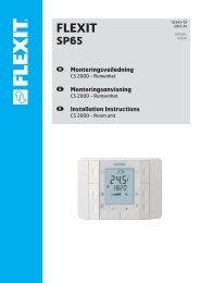
94269E-02<br />
2009-02<br />
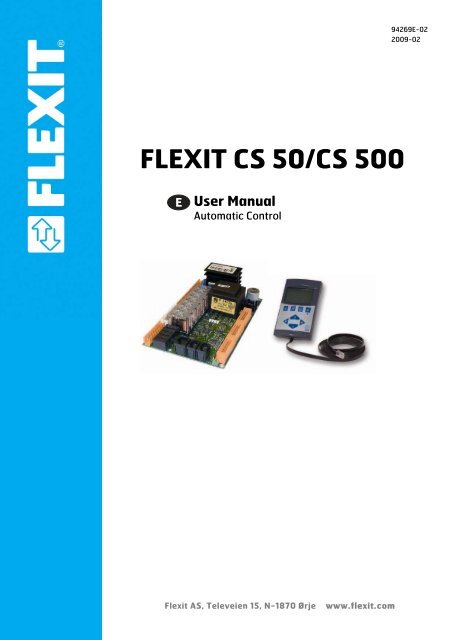
FLEXIT <strong>CS</strong> <strong>50</strong>/<strong>CS</strong> <strong>50</strong>0<br />
<strong>User</strong> <strong>Manual</strong><br />
<strong>Automatic</strong> <strong>Control</strong><br />
<strong>Flexit</strong> AS, Televeien 15, N-1870 Ørje<br />
www.flexit.com
Contents<br />
1 Overview..........................................................................................................6<br />
1.1 Brief Description...............................................................................................6<br />
1.2 Functions .........................................................................................................6<br />
1.3 Accessories for the <strong>CS</strong> <strong>50</strong>0 .............................................................................7<br />
1.4 Safety Comments ............................................................................................8<br />
1.4.1 Requirements for Installation Engineers/System Operators............................8<br />
1.5 Environmental Info: Protection/Disposal ..........................................................8<br />
2 Handling...........................................................................................................9<br />
2.1 Installation Procedure ......................................................................................9<br />
2.1.1 <strong>Control</strong>ler .........................................................................................................9<br />
2.1.2 Fault Management ...........................................................................................9<br />
2.1.3 CI <strong>50</strong>0 (Operator Unit) ...................................................................................10<br />
2.2 Connection Terminals ....................................................................................11<br />
3 Operation .......................................................................................................13<br />
3.1 CI <strong>50</strong>0 Operating Elements............................................................................13<br />
3.2 General Information on Navigation ................................................................14<br />
3.2.1 Levels.............................................................................................................14<br />
3.2.2 Menus ............................................................................................................15<br />
3.2.3 Password .......................................................................................................15<br />
3.2.4 Overview of the Menu Structure ....................................................................16<br />
3.2.5 Alarm List .......................................................................................................22<br />
3.2.6 Overview of End <strong>User</strong> Parameters ................................................................23<br />
4 Description of the Functions ..........................................................................30<br />
4.1 Menu Language Selection .............................................................................30<br />
4.2 Activation of Filter Replacement Time Counter .............................................30<br />
4.3 Period of Time for Filter Replacement ...........................................................30<br />
4.4 Resetting the Time Counter ...........................................................................30<br />
4.5 Activation of Supply Air Pressure Guard........................................................31<br />
4.6 Activation of Extract Air Pressure Guard .......................................................31<br />
4.7 External Fire/Smoke Function, Mode 1..........................................................31<br />
4.8 External Fire/Smoke Function, Mode 2..........................................................31<br />
4.9 External Fire/Smoke Function, Mode 3..........................................................32<br />
4.10 Date/Time ......................................................................................................32<br />
4.11 Change Service Code....................................................................................32<br />
4.12 Daily Timer.....................................................................................................32<br />
4.13 Weekly Timer .................................................................................................34<br />
4.14 Resetting to Factory Settings.........................................................................35<br />
4.15 Configuration of Temperature <strong>Control</strong> ...........................................................35<br />
4.15.1 <strong>Control</strong> Function 1, Constant Supply Air Temperature ..................................35<br />
4.15.2 <strong>Control</strong> Function 2, Room or Extract Air <strong>Control</strong> (not <strong>CS</strong> <strong>50</strong>) .....................366<br />
4.15.3 <strong>Control</strong> Function 3, Diff (not <strong>CS</strong> <strong>50</strong>)...............................................................36<br />
4.15.4 <strong>Control</strong> Function 4, Supply Air <strong>Control</strong> Compensated for Outdoor Air (not <strong>CS</strong><br />
<strong>50</strong>) ....................................................................................................................36<br />
4.16 <strong>Control</strong> Type Selection...................................................................................37<br />
4.17 Temperature Setting, Main Sensor ..............................................................377<br />
4.18 Extract Air <strong>Control</strong> Selection (not <strong>CS</strong> <strong>50</strong>).....................................................377<br />
4.19 Min. Supply Air Temperature (not <strong>CS</strong> <strong>50</strong>)....................................................388<br />
4.20 Max. Supply Air Temperature (not <strong>CS</strong> <strong>50</strong>)...................................................388<br />
4.21 Fan Reduction with Low Supply Air Temperature........................................388<br />
FLEXIT AS 94269<br />
<strong>CS</strong> <strong>50</strong>/<strong>CS</strong> <strong>50</strong>0 <strong>User</strong> <strong>Manual</strong><br />
2/67
4.22 Outdoor Air Compensation (not <strong>CS</strong> <strong>50</strong>).......................................................388<br />
4.23 Compensate for High Summer Temperature (not <strong>CS</strong> <strong>50</strong>) ............................39<br />
4.24 Stop Summer Compensation (not <strong>CS</strong> <strong>50</strong>) .....................................................39<br />
4.25 Start Summer Compensation (not <strong>CS</strong> <strong>50</strong>).....................................................39<br />
4.26 Compensate for Low Outdoor Air Temperature (not <strong>CS</strong> <strong>50</strong>).........................39<br />
4.27 Stop Winter Compensation (not <strong>CS</strong> <strong>50</strong>) ........................................................39<br />
4.28 Start Winter Compensation (not <strong>CS</strong> <strong>50</strong>) ........................................................40<br />
4.29 DIF <strong>Control</strong> Selection (not <strong>CS</strong> <strong>50</strong>) .................................................................40<br />
4.30 Desired Temperature Differential (not <strong>CS</strong> <strong>50</strong>) ...............................................40<br />
4.31 Min. Supply Air Temperature (not <strong>CS</strong> <strong>50</strong>) .....................................................40<br />
4.32 Max. Supply Air Temperature (not <strong>CS</strong> <strong>50</strong>) ..................................................411<br />
4.33 <strong>Automatic</strong> Switching between Extract Air and Supply Air <strong>Control</strong><br />
(not <strong>CS</strong> <strong>50</strong>).......................................................................................................41<br />
4.34 TempSwitchSup/Ext (not <strong>CS</strong> <strong>50</strong>)...................................................................41<br />
4.35 Delta Temp. for Resetting (not <strong>CS</strong> <strong>50</strong>) ..........................................................41<br />
4.36 Step <strong>Control</strong> (not <strong>CS</strong> <strong>50</strong>) ...............................................................................42<br />
4.37 External Temperature <strong>Control</strong> (not <strong>CS</strong> <strong>50</strong>)....................................................42<br />
4.38 Cooling (not <strong>CS</strong> <strong>50</strong>) .......................................................................................42<br />
4.39 Outdoor Air Temperature for Start of Cooling (not <strong>CS</strong> <strong>50</strong>) ..........................433<br />
4.40 Time between Each Start (not <strong>CS</strong> <strong>50</strong>)...........................................................43<br />
4.41 Minimum Speed for Cooling (not <strong>CS</strong> <strong>50</strong>).......................................................44<br />
4.42 Selection of Linear <strong>Control</strong> for DX Machine (not <strong>CS</strong> <strong>50</strong>) ..............................44<br />
4.43 DX Stage 2 (not transformer control).............................................................44<br />
4.44 Selection of Binary <strong>Control</strong> for DX Machine (not <strong>CS</strong> <strong>50</strong>)..............................44<br />
4.45 DX Stage 2 (not <strong>CS</strong> <strong>50</strong>).................................................................................45<br />
4.46 DX Stage 3 (not <strong>CS</strong> <strong>50</strong>).................................................................................45<br />
4.47 Activation of Cooling Recovery System (not <strong>CS</strong> <strong>50</strong>) ....................................45<br />
4.48 Start Temp. Differential for Cooling Recovery (not <strong>CS</strong> <strong>50</strong>)............................45<br />
4.49 Calibration with Measured Values + Activation of Sensors ...........................46<br />
4.<strong>50</strong> Neutral Zones ................................................................................................46<br />
4.51 Speed Stage 1, Supply Air ............................................................................47<br />
4.52 Speed Stage 2, Supply Air ............................................................................47<br />
4.53 Speed Stage 3, Supply Air ............................................................................47<br />
4.54 Speed Stage 1, Extract Air ............................................................................47<br />
4.55 Speed Stage 2, Extract Air ............................................................................48<br />
4.56 Speed Stage 3, Extract Air ............................................................................48<br />
4.57 <strong>Manual</strong> <strong>Control</strong> of Fan Speed........................................................................48<br />
4.58 Forced Ventilation..........................................................................................48<br />
4.59 Speed for Forcing ..........................................................................................48<br />
4.60 Time for Forcing ............................................................................................49<br />
4.61 DCV <strong>Control</strong> (not <strong>CS</strong> <strong>50</strong>/transformer control)................................................49<br />
4.62 Supply Air DCV <strong>Control</strong> (not <strong>CS</strong> <strong>50</strong>/transformer control) ..............................49<br />
4.63 Min. Extract Air (not <strong>CS</strong> <strong>50</strong>/transformer control)............................................49<br />
4.64 Max. Extract Air (not <strong>CS</strong> <strong>50</strong>/transformer control)...........................................<strong>50</strong><br />
4.65 Desired Supply Air Working Point (not <strong>CS</strong> <strong>50</strong>/transformer control)..............<strong>50</strong><br />
4.66 Extract Air DCV <strong>Control</strong> (not <strong>CS</strong> <strong>50</strong>/transformer control) ..............................<strong>50</strong><br />
4.67 Min. Supply Air (not <strong>CS</strong> <strong>50</strong>/transformer control)............................................<strong>50</strong><br />
4.68 Max. Supply Air (not <strong>CS</strong> <strong>50</strong>/transformer control)...........................................51<br />
4.69 Desired Working Point (not <strong>CS</strong> <strong>50</strong>/transformer control) ................................51<br />
4.70 Supply Air Constant Pressure <strong>Control</strong> (not <strong>CS</strong> <strong>50</strong>/transformer control) .......51<br />
4.71 Desired Working Point (not <strong>CS</strong> <strong>50</strong>/transformer control) ..............................511<br />
FLEXIT AS 94269<br />
<strong>CS</strong> <strong>50</strong>/<strong>CS</strong> <strong>50</strong>0 <strong>User</strong> <strong>Manual</strong><br />
3/67
4.72 Min. Supply Air (not <strong>CS</strong> <strong>50</strong>/transformer control) ............................................52<br />
4.73 Max. Supply Air (not <strong>CS</strong> <strong>50</strong>/transformer control) ...........................................52<br />
4.74 Extract Air Constant Pressure <strong>Control</strong> (not <strong>CS</strong> <strong>50</strong>/transformer control) .......52<br />
4.75 Desired Working Point (not <strong>CS</strong> <strong>50</strong>/transformer control).................................52<br />
4.76 Min. Extract Air (not <strong>CS</strong> <strong>50</strong>/transformer control) ............................................53<br />
4.77 Max. Extract Air (not <strong>CS</strong> <strong>50</strong>/transformer control) ...........................................53<br />
4.78 No. of External Fan Sensors (not <strong>CS</strong> <strong>50</strong>/transformer control) .......................53<br />
4.79 With One Sensor – Second Fan % Differential (not <strong>CS</strong> <strong>50</strong>/<br />
transformer control)........................................................................................53<br />
4.80 Selection of Sensor Type for Supply Air (not <strong>CS</strong> <strong>50</strong>/<br />
transformer control)........................................................................................54<br />
4.81 Min. Working Range for Supply Air Sensor (not <strong>CS</strong> <strong>50</strong>/<br />
transformer control)........................................................................................54<br />
4.82 Max. Working Range for Supply Air Sensor (not <strong>CS</strong> <strong>50</strong>/<br />
transformer control)........................................................................................54<br />
4.83 Selection of Sensor for Extract Air (not <strong>CS</strong> <strong>50</strong>/transformer control) .............54<br />
4.84 Min. Working Range for Extract Air Sensor (not <strong>CS</strong> <strong>50</strong>/<br />
transformer control)........................................................................................54<br />
4.85 Max. Working Range for Extract Air Sensor (not <strong>CS</strong> <strong>50</strong>/<br />
transformer control)........................................................................................55<br />
4.86 Motor Protection Delay ..................................................................................55<br />
4.87 Startup ...........................................................................................................55<br />
4.88 Start Delay for Extract Air Fan, Speed 1........................................................55<br />
4.89 Start Delay for Extract Air Fan, Normal Operation.........................................56<br />
4.90 Start Delay for Supply Air Fan, Speed 1 ........................................................56<br />
4.91 Start Delay Supply Air Fan, Normal Operation ..............................................56<br />
4.92 Overtravel ......................................................................................................56<br />
4.93 Components...................................................................................................56<br />
4.94 Printed Circuit Board Version.........................................................................57<br />
4.95 Printed Circuit Board Version.........................................................................57<br />
4.96 Factory Settings .............................................................................................57<br />
4.97 Operating Hours Counter...............................................................................57<br />
4.98 Active Alarms .................................................................................................57<br />
4.99 Alarm History .................................................................................................58<br />
4.100 Resetting Alarms............................................................................................58<br />
4.101 <strong>Manual</strong> Override ............................................................................................58<br />
4.102 Sensor Temperature Display .........................................................................58<br />
5 Description of I/O ...........................................................................................59<br />
5.1 J1 (Pin 1) PE..................................................................................................59<br />
5.2 J1 (Pin 2, 3) Power Supply to the Board........................................................59<br />
5.3 J1 (Pin 4, 5) Pump, Water Battery, or Stage 2, Electric Battery ....................59<br />
5.4 J1 (Pin 6, 7) Not in Use..................................................................................59<br />
5.5 J1 (Pin 8, 9, 10) Outdoor Air Damper ............................................................59<br />
5.6 J1 (Pin 11, 12) Supply Air Fan Operating Voltage .........................................59<br />
5.7 J1 (Pin 14, 15) Extract Air Fan Operating Voltage.........................................59<br />
5.8 J1 (Pin 13 - 16) ..............................................................................................59<br />
5.9 J2 (Pin 1, 2) 230 V Supply .............................................................................60<br />
5.10 J2 (Pin 3) Input from Transformer Speed 1, Supply Air .................................60<br />
5.11 J2 (Pin 4) Input from Transformer Speed 2, Supply Air .................................60<br />
5.12 J2 (Pin 5) Input from Transformer Speed 3, Supply Air .................................60<br />
5.13 J2 (Pin 6) Input from Transformer Speed 1, Extract Air.................................60<br />
5.14 J2 (Pin 7) Input from Transformer Speed 2, Extract Air.................................60<br />
FLEXIT AS 94269<br />
<strong>CS</strong> <strong>50</strong>/<strong>CS</strong> <strong>50</strong>0 <strong>User</strong> <strong>Manual</strong><br />
4/67
5.15 J2 (Pin 8) Input from Transformer Speed 3, Extract Air ................................60<br />
5.16 J3 (Pin 1, 4) Alarm Output Priority A (not <strong>CS</strong> <strong>50</strong>) .........................................62<br />
5.17 J3 (Pin 2, 4) Alarm Output Priority B (not <strong>CS</strong> <strong>50</strong>) .........................................62<br />
5.18 J3 (Pin 5) Not in Use (not <strong>CS</strong> <strong>50</strong>) ..................................................................63<br />
5.19 J3 (Pin 6, 8) DX Stage 1 (not <strong>CS</strong> <strong>50</strong>) ............................................................63<br />
5.20 J3 (Pin 7, 8) DX Stage 2 (not <strong>CS</strong> <strong>50</strong>) ............................................................63<br />
5.21 J4 (Pin 1, G0) External <strong>Control</strong>, Speed 1 (not <strong>CS</strong> <strong>50</strong>)..................................63<br />
5.22 J4 (Pin 2, G0) External <strong>Control</strong>, Speed 2 (not <strong>CS</strong> <strong>50</strong>)..................................63<br />
5.23 J4 (Pin 3, G0) External Fire/Smoke Alarm (not <strong>CS</strong> <strong>50</strong>) ................................63<br />
5.24 J4 (Pin 4, G0) Heating OFF/ON with an External Signal (not <strong>CS</strong> <strong>50</strong>) ...........63<br />
5.25 J4 (Pin 5, 6) Temperature Setting (not <strong>CS</strong> <strong>50</strong>) ..............................................64<br />
5.26 J4 (Pin 7, G0) Temperature Readout, Supply Air (not <strong>CS</strong> <strong>50</strong>) ......................64<br />
5.27 J4 (Pin 8, G0) Temperature Readout, Extract Air (not <strong>CS</strong> <strong>50</strong>) ......................64<br />
5.28 J4 (Pin 9, G0) Temperature Readout, Outdoor Air (not <strong>CS</strong> <strong>50</strong>) ....................64<br />
5.29 J4 (Pin 10, 11) Extract Air Temperature Sensor (not <strong>CS</strong> <strong>50</strong>) ........................64<br />
5.30 J4 (Pin 12, 13) Outdoor Air Temperature Sensor (not <strong>CS</strong> <strong>50</strong>) ......................64<br />
5.31 J4 (Pin 14, G0) External Pressure Sensor, Supply Air (not <strong>CS</strong> <strong>50</strong>)...............64<br />
5.32 J4 (Pin 16, G0) External Pressure Sensor, Extract Air (not <strong>CS</strong> <strong>50</strong>) ..............64<br />
5.33 J5 (Pin 1, 2) Supply Air Temperature Sensor................................................65<br />
5.34 J5 (Pin 3, 4) Temperature Sensor, Water Battery ........................................65<br />
5.35 J5 (Pin 5, 8) Electric Battery Thermostat.......................................................65<br />
5.36 J5 (Pin 6, 7) Not in Use .................................................................................65<br />
5.37 J5 (Pin 9, 10) <strong>Control</strong> Signal for Heating 0-10 V ...........................................65<br />
5.38 J5 (Pin 11, 12) <strong>Control</strong> Signal to Recovery System ......................................65<br />
5.39 J5 (Pin 13, 14) Rotor Alarm ...........................................................................66<br />
5.40 J5 (Pin 15, G0) External Start/Stop ...............................................................66<br />
5.41 J5 (Pin 16, G0) Forced Ventilation ................................................................66<br />
5.42 J6 (Pin 1, 3) Supply Air Fan <strong>Control</strong> Signal (0-10 V) ....................................66<br />
5.43 J6 (Pin 2, G0) Start/Stop Supply Air Fan (0-10 V).........................................66<br />
5.44 J6 (Pin 4, 5) Supply Air Fan and Extract Air Fan Motor Protection ...............66<br />
5.45 J6 (Pin 7, 9) Extract Air Fan <strong>Control</strong> Signal (0-10 V)....................................66<br />
5.46 J6 (Pin 8, G0) Start/Stop Extract Air Fan (0-10 V).........................................66<br />
5.47 J6 (Pin 10, G0) Supply Air Pressure Guard (not <strong>CS</strong> <strong>50</strong>) ..............................66<br />
5.48 J6 (Pin 12, G0) Extract Air Pressure Guard (not <strong>CS</strong> <strong>50</strong>) ..............................67<br />
5.49 J6 (Pin 13, 14) PWM Heating <strong>Control</strong> OFF/ON (not <strong>CS</strong> <strong>50</strong>) .........................67<br />
5.<strong>50</strong> J6 (Pin 15, 16) Cooling 0-10 V (not <strong>CS</strong> <strong>50</strong>) ...................................................67<br />
5.51 ISDN Contact for Plate Exchanger ................................................................67<br />
FLEXIT AS 94269<br />
<strong>CS</strong> <strong>50</strong>/<strong>CS</strong> <strong>50</strong>0 <strong>User</strong> <strong>Manual</strong><br />
5/67
1 Overview<br />
1.1 Brief Description<br />
<strong>Control</strong>lers for standardised ventilation applications.<br />
• <strong>Control</strong>, indication and monitoring functions<br />
• Temperature, pressure and air flow rate sequences<br />
• Sensor for winter and/or summer compensation<br />
• Time channels (4 day programmes and 6 week programmes)<br />
1.2 Functions<br />
<strong>Control</strong> Functions<br />
Monitoring Functions<br />
• Four types of control<br />
1. Constant supply air temperature<br />
2. Room/extract air control (not <strong>CS</strong> <strong>50</strong>)<br />
3. Dif - temperature control (not <strong>CS</strong> <strong>50</strong>)<br />
4. Supply air control compensated for outdoor air (not <strong>CS</strong> <strong>50</strong>)<br />
• Minimum and maximum limits for supply air temperature<br />
• Night cooling function (not <strong>CS</strong> <strong>50</strong>)<br />
• Setpoint value changeover via an external signal (not <strong>CS</strong> <strong>50</strong>)<br />
• Anti-icing function for plate exchanger, thermoguard – patented solution<br />
• Requirement-controlled ventilation (not <strong>CS</strong> <strong>50</strong>)<br />
• Frost protection function for the air or water side<br />
• Electric heating battery or water battery<br />
• Heat recovery with rotary wheel-type or plate exchanger<br />
• Pressure or air flow rate control (not <strong>CS</strong> <strong>50</strong>)<br />
• Circulation pump maintenance operation<br />
• Additional fan cooling<br />
• Cooling (not <strong>CS</strong> <strong>50</strong>)<br />
• Operate the controller externally or via a pushbutton<br />
• Common alarm with a contact output (priority A and B)<br />
• <strong>Control</strong> unit with 8-line display and 20 characters on each line<br />
• Input for fire or smoke alarm (not <strong>CS</strong> <strong>50</strong>)<br />
• Frost alarm in water battery<br />
• Electric battery, thermostat<br />
• Fans, overload (not <strong>CS</strong> <strong>50</strong>)<br />
• Filter alarm<br />
• Rotor alarm<br />
FLEXIT AS 94269<br />
<strong>CS</strong> <strong>50</strong>/<strong>CS</strong> <strong>50</strong>0 <strong>User</strong> <strong>Manual</strong><br />
6/67
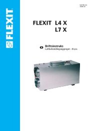
1.3 Accessories for the <strong>CS</strong> <strong>50</strong>0<br />
The list below contains examples of equipment that can be used with the <strong>CS</strong> <strong>50</strong>0.<br />
CC 10<strong>50</strong> Pressure Censor<br />
Art. no. 09367<br />
0-3000 Pa<br />
SP 440 CO 2 Detector<br />
Art. no. 09359<br />
SP 430 Pressure Regulator<br />
Art. no. 09357<br />
For external<br />
pressure adjustment<br />
SP 445 Smoke Detector<br />
(duct mounted)<br />
Art. no. 09362<br />
SP 435 Movement Censor<br />
Art. no. 09358<br />
For 24V<br />
SP 4<strong>50</strong> Movement Censor<br />
Art. no. 09390<br />
For 230V<br />
FLEXIT AS 94269<br />
<strong>CS</strong> <strong>50</strong>/<strong>CS</strong> <strong>50</strong>0 <strong>User</strong> <strong>Manual</strong><br />
7/67
1.4 Safety Comments<br />
Use with Other Products<br />
The <strong>CS</strong> <strong>50</strong>0 is designed exclusively for the control and monitoring of ventilation units.<br />
Only third-party products that <strong>Flexit</strong> has supplied with the <strong>CS</strong> <strong>50</strong>0 unit or that <strong>Flexit</strong> has<br />
recommended can be integrated in the system without restrictions. In relation to the<br />
overall configuration, the user must follow all safety instructions from the suppliers of<br />
such products.<br />
It is possible to connect or integrate third-party products that have not been<br />
recommended by <strong>Flexit</strong>, but such products must meet the safety requirements and<br />
other technical requirements specified in the relevant product descriptions.<br />
1.4.1 Requirements for Installation Engineers/System Operators<br />
Preparatory work on and commissioning of the <strong>CS</strong> <strong>50</strong>0 unit must be performed by<br />
qualified personnel who have received training from <strong>Flexit</strong>.<br />
The <strong>CS</strong> <strong>50</strong>0 must only be operated by people who have received adequate training<br />
from <strong>Flexit</strong> or <strong>Flexit</strong>’s representatives and have acquired knowledge of possible risk<br />
areas.<br />
1.5 Environmental Info: Protection/Disposal<br />
Environmental<br />
Protection<br />
Disposal<br />
The <strong>CS</strong> <strong>50</strong>0 controller has no negative impact on the environment.<br />
The symbol on the product shows that this product must not be treated as household<br />
waste. It must be taken to a reception station for recirculation of electric and electronic<br />
equipment.<br />
By ensuring the correct disposal of the equipment, you will contribute to preventing the<br />
negative consequences for the environment and health that incorrect handling may<br />
entail. For further information on recirculation of this product, please contact your local<br />
authority, your refuse collection company or the company from which you purchased it.<br />
FLEXIT AS 94269<br />
<strong>CS</strong> <strong>50</strong>/<strong>CS</strong> <strong>50</strong>0 <strong>User</strong> <strong>Manual</strong><br />
8/67
2 Handling<br />
2.1 Installation Procedure<br />
2.1.1 <strong>Control</strong>ler<br />
The <strong>CS</strong> <strong>50</strong>0 controller is mounted on 5 distance sleeves. The terminals are divisible<br />
(can be removed from the printed circuit board) to allow the controller to be replaced<br />
easily. Remember to make the unit dead first.<br />
STOP<br />
Electrical connections must be done in the following order:<br />
Peripheral equipment first and then the mains voltage.<br />
2.1.2 Fault Management<br />
If a fault should occur, check the following first:<br />
• The power supply is 230 V AC<br />
• The peripheral units are correctly connected<br />
• Fault diagnosis using the LEDs on the unit<br />
• Fault diagnosis using the alarm menu in the handheld terminal.<br />
If going through the above list does not help to locate and repair the fault, the controller<br />
must be replaced and the defective part returned (via your dealer) to the factory.<br />
FLEXIT AS 94269<br />
<strong>CS</strong> <strong>50</strong>/<strong>CS</strong> <strong>50</strong>0 <strong>User</strong> <strong>Manual</strong><br />
9/67
2.1.3 CI <strong>50</strong>0 (Operator Unit)<br />
On the rear of the CI <strong>50</strong>0 is an opening that allows the operator unit to be hung on the<br />
wall.<br />
Installation drawing for panel holder.<br />
10/67<br />
FLEXIT AS 94269<br />
<strong>CS</strong> <strong>50</strong>/<strong>CS</strong> <strong>50</strong>0 <strong>User</strong> <strong>Manual</strong>
2.2 Connection Terminals<br />
<strong>CS</strong> <strong>50</strong>0 Function<br />
IO<br />
Connection<br />
IO<br />
Type<br />
<strong>CS</strong> <strong>50</strong>0<br />
J1<br />
J1 PE Digital J1 (Pin 1)<br />
Connection<br />
Component<br />
J1 Main supply Digital (230 V) J1 (Pin 2, 3)<br />
J1 Pump (water battery)/<br />
Digital (230 V 11 A) J1 (Pin 4, 5)<br />
heating stage 2 (electric battery)<br />
J1 Not in use Digital J1 (Pin 6, 7)<br />
J1 Outdoor air damper (Pin 8 = L ON/OFF Pin Digital (230 V 2 A) J1 (Pin 8, 9, 10)<br />
9 = L Pin 10 = N)<br />
J1 Operating voltage for supply air motor Digital 85-230 V AC J1 (Pin 11, 12)<br />
J1 Operating voltage for extract air motor Digital 85-230 V AC J1 (Pin 14-15)<br />
J2 (only transformator control)<br />
J2 L phase output 230 V AC 5 A J2 (Pin 1)<br />
J2 N phase output 230 V AC 5 A J2 (Pin 2)<br />
J2 Supply air fan speed 1. Relay output 230 V AC 5 A J2 (Pin 3)<br />
J2 Supply air fan speed 2. Relay output 230 V AC 5 A J2 (Pin 4)<br />
J2 Supply air fan speed 3. Relay output 230 V AC 5 A J2 (Pin 5)<br />
J2 Extract air fan speed 1. Relay output 230 V AC 5 A J2 (Pin 6)<br />
J2 Extract air fan speed 2. Relay output 230 V AC 5 A J2 (Pin 7)<br />
J2 Extract air fan speed 3. Relay output 230 V AC 5 A J2 (Pin 8)<br />
J3 (not <strong>CS</strong> <strong>50</strong>)<br />
J3 Alarm output priority A Digital J3 (Pin 1, 4) (not <strong>CS</strong> <strong>50</strong>)<br />
J3 Alarm output priority B Digital J3 (Pin 2, 4) (not <strong>CS</strong> <strong>50</strong>)<br />
J3 Operation OK Digital J3 (Pin 3,4) (not <strong>CS</strong> <strong>50</strong>)<br />
J3 Not in use J3 (Pin 5)<br />
J3 DX cooling stage 1 Digital (230 V 1 A) J3 (Pin 6, 8) (not <strong>CS</strong> <strong>50</strong>)<br />
J3 DX cooling stage 2 Digital (230 V 1 A) J3 (Pin 7, 8) (not <strong>CS</strong> <strong>50</strong>)<br />
J4 (not <strong>CS</strong> <strong>50</strong>)<br />
J4 External control speed 1 Digital J4 (Pin 1, G0) (not <strong>CS</strong> <strong>50</strong>)<br />
J4 External control speed 2 Digital J4 (Pin 2, G0) (not <strong>CS</strong> <strong>50</strong>)<br />
J4 Alarm, external fire/smoke Digital J4 (Pin 3, G0) (not <strong>CS</strong> <strong>50</strong>)<br />
J4 Heating OFF/ON. External signal Digital J4 (Pin 4, G0) (not <strong>CS</strong> <strong>50</strong>)<br />
J4 Temperature setting. External signal Analogue (0 - 10 V) J4 (Pin 5, 6) (not <strong>CS</strong> <strong>50</strong>)<br />
J4 Supply air temperature reading Analogue (0 - 10 V) J4 (Pin 7, G0) (not <strong>CS</strong> <strong>50</strong>)<br />
J4 Extract air temperature reading Analogue (0 - 10 V) J4 (Pin 8, G0) (not <strong>CS</strong> <strong>50</strong>)<br />
J4 Outdoor air temperature reading Analogue (0 - 10 V) J4 (Pin 9, G0) (not <strong>CS</strong> <strong>50</strong>)<br />
J4 Extract air/room temperature NTC J4 (Pin 10, 11) (not <strong>CS</strong> <strong>50</strong>)<br />
J4 Outdoor air temperature NTC J4 (Pin 12, 13) (not <strong>CS</strong> <strong>50</strong>)<br />
J4 External pressure sensor, supply air Analogue (0 - 10 V) J4 (Pin 14, G0) (not <strong>CS</strong> <strong>50</strong>)<br />
J4 External pressure sensor, extract air Analogue (0 - 10 V) J4 (Pin 16, G0) (not <strong>CS</strong> <strong>50</strong>)<br />
J5<br />
J5 Supply air temperature sensor NTC J5 (Pin 1, 2)<br />
J5 Frost/ice sensor, water battery NTC J5 (Pin 3, 4)<br />
J5 Thermostat manual reset, electric battery Digital J5 (Pin 5, 8)<br />
J5 12 V 30 mA supply Analogue 12 V DC J5 (Pin 6, 7)<br />
J5 Heating, full range water battery Analogue (0 - 10 V) J5 (Pin 9, 10)<br />
J5 Rotor or bypass motor Analogue (0 - 10 V) J5 (Pin 11, 12)<br />
J5 Rotor: rotor alarm Digital J5 (Pin 13, 14)<br />
11/67<br />
FLEXIT AS 94269<br />
<strong>CS</strong> <strong>50</strong>/<strong>CS</strong> <strong>50</strong>0 <strong>User</strong> <strong>Manual</strong>
<strong>CS</strong> <strong>50</strong>0 Function<br />
IO<br />
IO<br />
Type<br />
Connection<br />
<strong>CS</strong> <strong>50</strong>0<br />
Connection<br />
Component<br />
J5 External start/stop Digital J5 (Pin 15, G0)<br />
J5 Forced operation. Speed 3 Digital J5 (Pin 16, G0)<br />
J6<br />
J6 Supply air fan Analogue (0 - 10 V) J6 (Pin 1, 3)<br />
J6 Start/stop supply air fan Digital J6 (Pin 2, G0)<br />
J6 Alarm, supply air/extract air fan Digital J6 (Pin 4, 6)<br />
J6 12 V power supply Analogue (12 V DC) J6 (Pin 5)<br />
J6 Extract air fan Analogue (0 - 10 V) J6 (Pin 7, 9)<br />
J6 Start/stop extract air fan Digital J6 (Pin 8, G0)<br />
J6 Supply air pressure guard Digital J6 (Pin 10, G0) (not <strong>CS</strong> <strong>50</strong>)<br />
J6 Extract air pressure guard Digital J6 (Pin 12, G0) (not <strong>CS</strong> <strong>50</strong>)<br />
J6 Pulse with modulation (ON/OFF)Analogue J6 (Pin 13) (not <strong>CS</strong> <strong>50</strong>)<br />
J6 Cooling Analogue (0 - 10 V) J6 (Pin 15, 16) (not <strong>CS</strong> <strong>50</strong>)<br />
Microswitch ON OFF<br />
1 Rotating exchanger Cross heat exchanger<br />
2 Unit fitted with a water battery Unit fitted with an electric battery<br />
3 The unit has an exchanger with a<br />
bypass<br />
The unit has preheating (only if the unit has a plate<br />
exchanger)<br />
4 Not in use Not in use<br />
12/67<br />
FLEXIT AS 94269<br />
<strong>CS</strong> <strong>50</strong>/<strong>CS</strong> <strong>50</strong>0 <strong>User</strong> <strong>Manual</strong>
3 Operation<br />
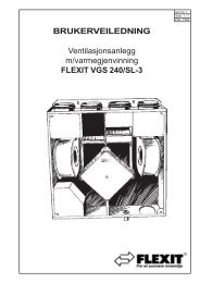
3.1 CI <strong>50</strong>0 Operating Elements<br />
1<br />
2<br />
3<br />
4<br />
5<br />
6<br />
7<br />
8<br />
Legend<br />
Operating element<br />
Home key<br />
Save key<br />
Enter<br />
Function<br />
Places the cursor on the home page<br />
again<br />
Confirms a change to a value (setting)<br />
Selects a menu/parameter/line<br />
Down or decrease value Moves the cursor and adjusts a value (-)<br />
Alarm key with integrated LED Display and confirmation of alarms<br />
Forcing/Stop<br />
Forced ventilation. Stops the unit if you<br />
hold the key in for 5 seconds<br />
Up or increase value Moves the cursor or adjusts a value (+)<br />
Return key (ESC)<br />
Places the cursor in the previous menu<br />
again<br />
If there is no activity for 10 minutes, the light in the panel will go out.<br />
13/67<br />
FLEXIT AS 94269<br />
<strong>CS</strong> <strong>50</strong>/<strong>CS</strong> <strong>50</strong>0 <strong>User</strong> <strong>Manual</strong>
3.2 General Information on Navigation<br />
3.2.1 Levels<br />
Data access is divided into three underlying levels:<br />
• Operator level<br />
• Service level<br />
• Factory level<br />
Operator level<br />
The end user has access to the operator level:<br />
On the operator level, the end user can read and change specific values without<br />
entering a password.<br />
Service level<br />
The service engineer has access to the service level:<br />
The end user does not have access to the service level. This level is designed<br />
exclusively for the service engineer, who gains access by entering the correct<br />
password. When the password has been entered, the engineer gains access to the<br />
second highest level and can read and change all values that are accessible on the<br />
service level.<br />
Factory level<br />
The HVAC engineer has access to the factory level:<br />
The end user and the service engineer do not have access to the factory level. This<br />
level is designed exclusively for the HVAC engineer, who gains access by entering the<br />
correct password. When the password has been entered, the engineer gains access to<br />
the highest level and can read and change all values.<br />
In this documentation, the terms “end user parameters”, “service engineer parameters”<br />
and “HVAC engineer parameters” refer to the settings defined via the parameter names<br />
(with the exception of the time channels). The basic settings (and the time channels) do<br />
not have these names.<br />
14/67<br />
FLEXIT AS 94269<br />
<strong>CS</strong> <strong>50</strong>/<strong>CS</strong> <strong>50</strong>0 <strong>User</strong> <strong>Manual</strong>
3.2.2 Menus<br />
You access the parameter names or setting lines via main menus (home page) and<br />
submenus.<br />
The order in which the menus for the individual parameter names or setting lines are<br />
selected is also explained in the overview and description.<br />
This appears as follows in the parameter overview:<br />
Function<br />
Parameter<br />
name<br />
Range<br />
Unit<br />
Default value<br />
Read<br />
Change<br />
Section<br />
Fan control ⎢Speed setting ⎢Supply air ⎢Parameter name<br />
Setting the speed Speed 1 0.0..100 %<br />
NB<br />
Depending on the application, not all parameters are used. Therefore, they are not<br />
displayed on the handheld terminal either. The parameters listed and described in this<br />
documentation are always displayed in the same order. The menus are always<br />
displayed.<br />
3.2.3 Password<br />
The password function ensures that the data is protected.<br />
Each password consists of 4 figures and is given within 3 levels.<br />
Password levels<br />
Info password (I)<br />
Service level (S)<br />
Factory level password (F)<br />
.<br />
for the information level (password not necessary!)<br />
for service engineers<br />
for the HVAC engineer<br />
The following numeric codes are used:<br />
Password<br />
Info Service level (S) Factory level code (F)<br />
password (I)<br />
Level 0 1 2<br />
Numeric code 0000 1000 xxxx<br />
NB<br />
The password levels are structured hierarchically. This means that if password 3 is<br />
entered, everything on password level 1 or 2 can be read or written as well.<br />
15/67<br />
FLEXIT AS 94269<br />
<strong>CS</strong> <strong>50</strong>/<strong>CS</strong> <strong>50</strong>0 <strong>User</strong> <strong>Manual</strong>
3.2.4 Overview of the Menu Structure<br />
Information<br />
Temperature setting<br />
Supply air:<br />
Extract air: (not <strong>CS</strong> <strong>50</strong>)<br />
Outdoor air: (not <strong>CS</strong> <strong>50</strong>)<br />
Thermoguard:<br />
Return water:<br />
Cooling: : (not <strong>CS</strong> <strong>50</strong>)<br />
Recovery system:<br />
Heating:<br />
Speed<br />
Timer:<br />
Temperature control type: (not <strong>CS</strong> <strong>50</strong>)<br />
Configuration<br />
Fan control type:<br />
Supply air:<br />
Extract air:<br />
Language<br />
English<br />
Norwegian<br />
Swedish<br />
Danish<br />
Finnish<br />
German<br />
Dutch<br />
Filter<br />
Time counter ON/OFF<br />
activated<br />
Period of time<br />
Reset time counter YES/NO<br />
Supply air ON/OFF<br />
pressure guard<br />
Extract air ON/OFF<br />
pressure guard<br />
Fire/Smoke Mode 1<br />
Mode 2<br />
Mode 3<br />
Clock<br />
Time<br />
Date<br />
PIN codes Service code Set new service code<br />
Timer<br />
Daily timer 1 Active ON/OFF<br />
Time ON<br />
Speed<br />
Temperature<br />
Temperature ON/OFF<br />
Active YES/NO<br />
Daily timer 2 Active ON/OFF<br />
Time ON<br />
Speed<br />
Temperature<br />
16/67<br />
FLEXIT AS 94269<br />
<strong>CS</strong> <strong>50</strong>/<strong>CS</strong> <strong>50</strong>0 <strong>User</strong> <strong>Manual</strong>
Daily timer 3<br />
Daily timer 4<br />
Weekly timer 1<br />
Weekly timer 2<br />
Weekly timer 3<br />
Weekly timer 4<br />
Weekly timer 5<br />
Temperature ON/OFF<br />
Active YES/NO<br />
Active ON/OFF<br />
Time ON<br />
Speed<br />
Temperature<br />
Temperature ON/OFF<br />
Active YES/NO<br />
Active ON/OFF<br />
Time ON<br />
Speed<br />
Temperature<br />
Temperature ON/OFF<br />
Active YES/NO<br />
Day ON<br />
Time ON<br />
Speed<br />
Temperature<br />
Temperature ON/OFF<br />
Time OFF<br />
Day OFF<br />
Active YES/NO<br />
Day ON<br />
Time ON<br />
Speed<br />
Temperature<br />
Temperature ON/OFF<br />
Day OFF<br />
Time OFF<br />
Active YES/NO<br />
Day ON<br />
Time ON<br />
Speed<br />
Temperature<br />
Temperature ON/OFF<br />
Day OFF<br />
Time OFF<br />
Active YES/NO<br />
Day ON<br />
Time ON<br />
Speed<br />
Temperature<br />
Temperature ON/OFF<br />
Day OFF<br />
Time OFF<br />
Active YES/NO<br />
Day ON<br />
Time ON<br />
Speed<br />
Temperature<br />
Temperature ON/OFF<br />
Day OFF<br />
17/67<br />
FLEXIT AS 94269<br />
<strong>CS</strong> <strong>50</strong>/<strong>CS</strong> <strong>50</strong>0 <strong>User</strong> <strong>Manual</strong>
Time OFF<br />
Active YES/NO<br />
Setting<br />
Weekly timer 6<br />
Save setting<br />
Reset<br />
Reset to factory<br />
setting<br />
Day ON<br />
Time ON<br />
Speed<br />
Temperature<br />
Temperature ON/OFF<br />
Day OFF<br />
Time OFF<br />
Active YES/NO<br />
YES/NO<br />
YES/NO<br />
YES/NO<br />
Temperature<br />
Setting<br />
<strong>Control</strong><br />
External temp.<br />
control<br />
Cooling:<br />
Temperature<br />
sensor<br />
Extract air<br />
(not <strong>CS</strong> <strong>50</strong>)<br />
FanSlow<br />
Comp (not <strong>CS</strong> <strong>50</strong>)<br />
Diff (not <strong>CS</strong> <strong>50</strong>)<br />
AutoExt/Sup<br />
(not <strong>CS</strong> <strong>50</strong>)<br />
Step control<br />
(not <strong>CS</strong> <strong>50</strong>)<br />
ON/OFF<br />
Min. outdoor air<br />
temp.<br />
Delay<br />
Min. speed<br />
Linear mode<br />
Binary mode<br />
Cooling recovery<br />
Thermoguard<br />
Supply air<br />
Extract air<br />
(not <strong>CS</strong> <strong>50</strong>)<br />
Outdoor<br />
ON/OFF<br />
Min. supply air<br />
Max. extract air<br />
ON/OFF<br />
ON/OFF<br />
Summer diff<br />
Stop summer<br />
Start summer<br />
Winter diff<br />
Stop winter<br />
Start winter<br />
ON/OFF<br />
Temp. diff<br />
Min. supply air<br />
Max. supply air<br />
ON/OFF<br />
Outdoor air temperature<br />
Deviation<br />
ON/OFF<br />
ON/OFF<br />
Step 2<br />
ON/OFF<br />
Step 2<br />
Step 3<br />
ON/OFF<br />
Diff temp.<br />
ON/OFF<br />
ON/OFF<br />
18/67<br />
FLEXIT AS 94269<br />
<strong>CS</strong> <strong>50</strong>/<strong>CS</strong> <strong>50</strong>0 <strong>User</strong> <strong>Manual</strong>
Fan control<br />
Neutral zone<br />
Number of speeds<br />
Return water<br />
Cooling recovery<br />
system (not <strong>CS</strong> <strong>50</strong>)<br />
Recovery system,<br />
heating<br />
ON/OFF<br />
Speed setting<br />
<strong>Manual</strong> setting<br />
Forced ventilation<br />
<strong>Control</strong> (not <strong>CS</strong><br />
<strong>50</strong>)<br />
Configuration<br />
Alarms<br />
Supply air Speed 1<br />
Speed 2<br />
Speed 3<br />
Extract air Speed 1<br />
Speed 2<br />
Speed 3<br />
Speed<br />
Activated<br />
ON/OFF<br />
Default speed<br />
Default time<br />
DCV supply air ON/OFF<br />
Output min. value<br />
Output max. value<br />
Input ON level<br />
DCV extract air ON/OFF<br />
Output min. value<br />
Output max. value<br />
Input ON level<br />
CPR supply air ON/OFF<br />
Desired value<br />
Min. value<br />
Max. value<br />
CPR extract air ON/OFF<br />
Desired value<br />
Min. value<br />
Max. value<br />
No. of fan sensors 2<br />
1 – Supply air<br />
1 – Extract air<br />
Differential<br />
Sensor, supply air Type<br />
Min. level<br />
Max. level<br />
Sensor, extract air Type<br />
Min. level<br />
Max. level<br />
Motor protection Delay<br />
Startup sequence Start delay 1<br />
Start delay 2<br />
Start delay 3<br />
Start delay 4<br />
Stop sequence Delay<br />
Active alarms<br />
Alarm history<br />
Reset alarm<br />
19/67<br />
FLEXIT AS 94269<br />
<strong>CS</strong> <strong>50</strong>/<strong>CS</strong> <strong>50</strong>0 <strong>User</strong> <strong>Manual</strong>
Test<br />
Information<br />
System<br />
Recovery<br />
system<br />
Heating<br />
Defrosting<br />
Main board<br />
Hardware rev.<br />
Software rev.<br />
<strong>Control</strong> panels<br />
<strong>CS</strong> <strong>50</strong>0 panel<br />
1:<br />
Hardware rev.<br />
Software rev.<br />
<strong>CS</strong> <strong>50</strong>0 panel<br />
2:<br />
Hardware rev.<br />
Software rev.<br />
<strong>CS</strong><strong>50</strong> panel 1:<br />
Hardware rev.<br />
Software rev.<br />
<strong>CS</strong><strong>50</strong> panel 2:<br />
Hardware rev.<br />
Software rev.<br />
Inputs/outputs Digital inputs 1<br />
Factory<br />
<strong>Control</strong><br />
parameters<br />
Fan parameters<br />
FVP<br />
Priorities<br />
Reset alarm<br />
history<br />
Temp.<br />
parameters<br />
Panel forced:<br />
FVP speed:<br />
CO:<br />
VVX:<br />
EV2:<br />
FV:<br />
SUPPLY AIR<br />
FAN:<br />
EXTRACT AIR<br />
FAN:<br />
YES/NO<br />
Alarms<br />
Test<br />
Time counter<br />
Filter timer<br />
Active alarms<br />
Alarm history<br />
Reset alarm<br />
Fan speed<br />
Heating<br />
Preheating<br />
Heat recovery<br />
system<br />
Cooling<br />
ON/OFF<br />
ON/OFF<br />
ON/OFF<br />
ON/OFF<br />
20/67<br />
FLEXIT AS 94269<br />
<strong>CS</strong> <strong>50</strong>/<strong>CS</strong> <strong>50</strong>0 <strong>User</strong> <strong>Manual</strong>
(not <strong>CS</strong> <strong>50</strong>)<br />
Alarm outputs (not<br />
<strong>CS</strong> <strong>50</strong>)<br />
Factory test<br />
Sensors<br />
ON/OFF<br />
ON/OFF<br />
Thermoguard<br />
Supply air<br />
Extract air<br />
(not <strong>CS</strong> <strong>50</strong>)<br />
Outdoor air<br />
(not <strong>CS</strong> <strong>50</strong>)<br />
Return water<br />
21/67<br />
FLEXIT AS 94269<br />
<strong>CS</strong> <strong>50</strong>/<strong>CS</strong> <strong>50</strong>0 <strong>User</strong> <strong>Manual</strong>
3.2.5 Alarm List<br />
Description<br />
The alarm list provides an overview of active alarms (alarms that are still on). Up to 5<br />
alarms can be displayed.<br />
B alarms: Reset automatically (except where filter timers have been used (not a<br />
pressure guard). This must be reset manually).<br />
A alarms: Must be reset manually (Test I Alarm I History I Reset Alarm).<br />
5<br />
Alarm point Input Alarm class Description<br />
A_Alarm - Joint alarm (class A alarm active)<br />
B_Alarm - Joint alarm (class B alarm active)<br />
Frost sensor out of<br />
range<br />
Supply air sensor out<br />
of range<br />
Extract air sensor out<br />
of range<br />
Outdoor air sensor out<br />
of range<br />
Return water sensor<br />
out of range<br />
Frost sensor not<br />
connected<br />
Thermostat active<br />
Fire/smoke sensor<br />
active (not <strong>CS</strong> <strong>50</strong>)<br />
Rotor alarm active<br />
Motor protection active<br />
(not <strong>CS</strong> <strong>50</strong>)<br />
Frost alarm, water<br />
battery<br />
Signal B6 +<strong>50</strong>°C<br />
Signal B1 +<strong>50</strong>°C<br />
Signal B3 +<strong>50</strong>°C<br />
Signal B4 +<strong>50</strong>°C<br />
Signal B5 +80°C<br />
Signal TA<br />
active<br />
Signal BT<br />
active<br />
Signal BR<br />
active<br />
Signal RA<br />
active<br />
Signal TP<br />
active<br />
Lowe return<br />
water<br />
temperature<br />
A<br />
A<br />
Temperature sensor in the plate exchanger is out of its<br />
measuring range.<br />
Sensor fault or sensor not connected.<br />
Temperature is out of its measuring range.<br />
Sensor fault or sensor not connected.<br />
A<br />
Temperature sensor in the plate exchanger is out of its<br />
measuring range.<br />
Sensor fault or sensor not connected.<br />
A<br />
Temperature sensor in the plate exchanger is out of its<br />
measuring range.<br />
Sensor fault or sensor not connected.<br />
A<br />
Temperature sensor in the plate exchanger is out of its<br />
measuring range.<br />
Sensor fault or sensor not connected.<br />
? Alarm unless the frost guard for the plate exchanger is<br />
connected (applies only to units with plate exchangers)<br />
A<br />
Overheating thermostat has been triggered on account of<br />
excessive temperature in electric battery<br />
A(*B)<br />
External signal from fire or smoke detector<br />
B<br />
A<br />
A<br />
Alarm from the rotor unit<br />
Alarm signal from motor protection. Joint alarm for the<br />
supply air and extract air fans<br />
Frost alarm from water battery on account of low<br />
temperature in the water battery<br />
Filter alarm Filter alarm B Filter replacement alarm (only in units without a pressure<br />
guard)<br />
Supply air filter alarm Signal TFI B Supply air filter alarm<br />
(not <strong>CS</strong> <strong>50</strong>)<br />
Extract air filter alarm<br />
(not <strong>CS</strong> <strong>50</strong>)<br />
Signal FFI B Extract air filter alarm<br />
* Here you can choose whether the unit is to stop or continue.<br />
22/67<br />
FLEXIT AS 94269<br />
<strong>CS</strong> <strong>50</strong>/<strong>CS</strong> <strong>50</strong>0 <strong>User</strong> <strong>Manual</strong>
3.2.6 Overview of End <strong>User</strong> Parameters<br />
Function<br />
Parameter<br />
name<br />
Range<br />
Unit<br />
Default<br />
value<br />
Read 1<br />
Change<br />
Information<br />
Supply air temperature Supply air temperature -<strong>50</strong>...1<strong>50</strong>,0 °C<br />
Extract air temperature Extract air temperature -<strong>50</strong>...1<strong>50</strong>,0 °C X<br />
Outdoor air temperature Outdoor air temperature -<strong>50</strong>...1<strong>50</strong>,0 °C X<br />
Thermoguard Thermoguard -<strong>50</strong>...1<strong>50</strong>,0 °C<br />
Return water Return water -<strong>50</strong>...1<strong>50</strong>,0 °C<br />
Cooling Cooling 0,0...100,0 % X<br />
Recovery system Recovery system 0,0...100,0 % X<br />
Heating Heating 0,0...100,0 %<br />
Speed Speed 0, 1, 2 or 3<br />
Timer Timer OFF, Day 1-<br />
4/Week 1-4<br />
Desired temperature Desired temperature -<strong>50</strong>...1<strong>50</strong>,0 °C<br />
Temperature control Temperature control Sup/Ext/DIF/Comp X<br />
Fan control<br />
Fan control<br />
Supply air Supply air Speed 0..3/VAV,<br />
CPR<br />
Extract air Extract air Speed 0..3/VAV,<br />
CPR<br />
Configuration ⎢Language ⎢Parameter name<br />
Language in handheld terminal Language<br />
English<br />
English<br />
(CI <strong>50</strong>0)<br />
Norwegian<br />
Swedish<br />
Danish<br />
Finnish<br />
German<br />
Dutch<br />
Configuration ⎢Filter ⎢Parameter name<br />
Time counter activated ON/OFF<br />
OFF<br />
Period of time 0…12 month 6<br />
s<br />
Reset time counter YES/NO NO<br />
Supply air pressure ON/OFF ON X<br />
guard<br />
Extract air pressure ON/OFF ON X<br />
guard<br />
Configuration ⎢Fire/Smoke ⎢Parameter name<br />
Fire function Mode 1<br />
Mode 1 X<br />
Mode 2<br />
Mode 3<br />
Configuration ⎢Clock ⎢Parameter name<br />
Clock Time 00:00...24:00<br />
Date Date dd.mm.yyyy<br />
Configuration ⎢PIN code ⎢Parameter name<br />
Service code 0 0 0 0 (0-9)<br />
Configuration ⎢PIN code ⎢Service code<br />
Set new service code 0 0 0 0 (0-9)<br />
Not <strong>CS</strong> <strong>50</strong><br />
23/67<br />
FLEXIT AS 94269<br />
<strong>CS</strong> <strong>50</strong>/<strong>CS</strong> <strong>50</strong>0 <strong>User</strong> <strong>Manual</strong>
Function<br />
Parameter<br />
name<br />
Range<br />
Unit<br />
Default<br />
value<br />
Read 1<br />
Change<br />
Not <strong>CS</strong> <strong>50</strong><br />
Configuration ⎢Timer ⎢ Daily timer 1 ⎢ Parameter name<br />
Time ON 00:00/24:00 06:00<br />
Speed 0,1,2,3 1<br />
Temperature 10...40,0 °C 20<br />
Temperature ON/OFF OFF<br />
Active YES/NO YES<br />
Configuration ⎢Timer ⎢ Daily timer 2 ⎢ Parameter name<br />
Time ON 00:00/24:00 06:00<br />
Speed 0,1,2,3 1<br />
Temperature 10...40,0 °C 20<br />
Temperature ON/OFF OFF<br />
Active YES/NO NO<br />
Configuration ⎢Timer ⎢Daily timer 3 ⎢Parameter name<br />
Time ON 00:00/24:00 06:00<br />
Speed 0,1,2,3 1<br />
Temperature 10...40,0 °C 20<br />
Temperature ON/OFF OFF<br />
Active YES/NO NO<br />
Configuration ⎢Timer ⎢Daily timer 4 ⎢Parameter name<br />
Time ON 00:00/24:00 06:00<br />
Speed 0,1,2,3 1<br />
Temperature 10...40,0 °C 20<br />
Temperature ON/OFF OFF<br />
Active YES/NO NO<br />
Configuration ⎢Timer ⎢Weekly timer 1 ⎢Parameter name<br />
Day ON Monday..Sunday Saturday<br />
Time ON 00:00/24:00 06:00<br />
Speed 0,1,2,3 1<br />
Temperature 10...40,0 °C 20<br />
Temperature ON/OFF OFF<br />
Time OFF 00:00/24:00 20:00<br />
Day OFF Monday..Sunday Sunday<br />
Day ON Monday..Sunday Saturday<br />
Active YES/NO NO<br />
Configuration ⎢Timer ⎢Weekly timer 2 ⎢Parameter name<br />
Day ON Monday..Sunday Saturday<br />
Time ON 00:00/24:00 06:00<br />
Speed 0,1,2,3 1<br />
Temperature 10...40,0 °C 20<br />
Temperature ON/OFF OFF<br />
Time OFF 00:00/24:00 20:00<br />
Day OFF Monday..Sunday Sunday<br />
Active YES/NO NO<br />
24/67<br />
FLEXIT AS 94269<br />
<strong>CS</strong> <strong>50</strong>/<strong>CS</strong> <strong>50</strong>0 <strong>User</strong> <strong>Manual</strong>
Configuration ⎢Timer ⎢Weekly timer 3 ⎢Parameter name<br />
Day ON Monday..Sunday Saturday<br />
Time ON 00:00/24:00 06:00<br />
Speed 0,1,2,3 1<br />
Temperature 10...40,0 °C 20<br />
Temperature ON/OFF OFF<br />
Time OFF 00:00/24:00 20:00<br />
Day OFF Monday..Sunday Sunday<br />
Active YES/NO NO<br />
Configuration ⎢Timer ⎢Weekly timer 4 ⎢Parameter name<br />
Day ON Monday..Sunday Saturday<br />
Time ON 00:00/24:00 06:00<br />
Speed 0,1,2,3 1<br />
Temperature 10...40,0 °C 20<br />
Temperature ON/OFF OFF<br />
Time OFF 00:00/24:00 20:00<br />
Day OFF Monday..Sunday Sunday<br />
Active YES/NO NO<br />
Configuration ⎢Timer ⎢Weekly timer 5 ⎢Parameter name<br />
Day ON Monday..Sunday Saturday<br />
Time ON 00:00/24:00 06:00<br />
Speed 0,1,2,3 1<br />
Temperature 10...40,0 °C 20<br />
Temperature ON/OFF OFF<br />
Time OFF 00:00/24:00 20:00<br />
Day OFF Monday..Sunday Sunday<br />
Active YES/NO NO<br />
Configuration ⎢Timer ⎢Weekly timer 6 ⎢Parameter name<br />
Day ON Monday..Sunday Saturday<br />
Time ON 00:00/24:00 06:00<br />
Speed 0,1,2,3 1<br />
Temperature 10...40,0 °C 20<br />
Temperature ON/OFF OFF<br />
Time OFF 00:00/24:00 20:00<br />
Day OFF Monday..Sunday Sunday<br />
Active YES/NO NO<br />
Configuration ⎢Setting ⎢Parameter name<br />
Save setting YES/NO NO<br />
Reset setting YES/NO NO<br />
Reset to factory<br />
setting<br />
YES/NO<br />
NO<br />
Temperature ⎢Setting ⎢Parameter name<br />
Setting 0...40,0 °C 20<br />
Temperature ⎢<strong>Control</strong> ⎢Extract air control ⎢Parameter name<br />
Extract air ON/OFF OFF X<br />
Min. supply air 5...25,0 °C 16 X<br />
Max. supply air 15...45,0 °C 35 X<br />
Temperature ⎢<strong>Control</strong> ⎢Fan reduction ⎢Parameter name<br />
FanSlow ON/OFF OFF<br />
Temperature ⎢<strong>Control</strong> ⎢Comp. ⎢Parameter name<br />
25/67<br />
FLEXIT AS 94269<br />
<strong>CS</strong> <strong>50</strong>/<strong>CS</strong> <strong>50</strong>0 <strong>User</strong> <strong>Manual</strong>
Comp. ON/OFF OFF X<br />
Summer diff -10...10,0 °C 2 X<br />
Stop summer 10...40,0 °C 30 X<br />
Start summer 10...40,0 °C 25 X<br />
Winter diff -10...10,0 °C 1 X<br />
Stop winter -30...20,0 °C -20 X<br />
Start winter -30...20,0 °C -30 X<br />
Temperature ⎢<strong>Control</strong> ⎢DIF ⎢Parameter name<br />
DIF ON/OFF OFF X<br />
Temp. diff -5...10,0 °C 2 X<br />
Min. supply air 5...25,0 °C 16 X<br />
Max. supply air 15...4<strong>50</strong>,0 °C 35 X<br />
Temperature ⎢<strong>Control</strong> ⎢AutoExt/Sup ⎢Parameter name<br />
AutoExt/Sup ON/OFF OFF X<br />
Outdoor air<br />
5...25,0 °C 15 X<br />
temperature<br />
Deviation 1...3,0 °C 2 X<br />
Temperature ⎢<strong>Control</strong> ⎢Night purging ⎢Parameter name<br />
Night purging ON/OFF OFF X<br />
Diff 1...20,0 °C 5 X<br />
Min. time 0…720 Min. 30 X<br />
Min. outdoor air temp. 5...30,0 °C 12 X<br />
Temperature ⎢<strong>Control</strong> ⎢Step control<br />
Step control ON/OFF OFF X<br />
Temperature ⎢External control ⎢Parameter name<br />
External control ON/OFF OFF X<br />
Temperature ⎢Cooling ⎢ Linear mode ⎢Parameter name<br />
Linear mode ON/OFF OFF X<br />
Stage 2 10-100 % <strong>50</strong> X<br />
Temperature ⎢Cooling ⎢Binary mode ⎢Parameter name<br />
Binary mode ON/OFF OFF X<br />
Stage 2 10-70 % 40 X<br />
Stage 3 <strong>50</strong>-100 % 80 X<br />
Temperature ⎢Cooling ⎢Cooling recovery ⎢Parameter name<br />
Cooling recovery ON/OFF OFF X<br />
Diff temp. 0...5 °C 1 X<br />
26/67<br />
FLEXIT AS 94269<br />
<strong>CS</strong> <strong>50</strong>/<strong>CS</strong> <strong>50</strong>0 <strong>User</strong> <strong>Manual</strong>
Function<br />
Parameter<br />
name<br />
Range<br />
Unit<br />
Default value<br />
Read 1<br />
Write 1<br />
Not <strong>CS</strong> <strong>50</strong><br />
Temperature ⎢Temperature sensors ⎢Calibration ⎢Parameter name<br />
Calibration of temp. sensor for plate Thermoguard -5.0...5.0 °C 0,0<br />
exchanger<br />
Supply air -5.0...5.0 °C 0,0<br />
Extract air -5.0...5.0 °C 0,0 X<br />
ON/OFF OFF X<br />
Outdoor air -5.0...5.0 °C 0,0 X<br />
ON/OFF OFF X<br />
Return water -5.0...5.0 °C 0,0<br />
Temperature ⎢Neutral zone ⎢Parameter name<br />
Cooling recovery -5.0...5.0 °C 0,0 X<br />
system<br />
Recovery system, -5.0...5.0 °C 0,0<br />
heating<br />
Fan control ⎢Speed setting ⎢Parameter name<br />
Speed 1 0-100 % 35<br />
Speed 2 0-100 % <strong>50</strong><br />
Speed 3 0-100 % 100<br />
Fan control ⎢<strong>Manual</strong> setting ⎢Parameter name<br />
Speed 0,1,2,3<br />
Fan control ⎢Forced ventilation ⎢Parameter name<br />
Activate OFF/ON OFF<br />
Default speed 0,1,2,3 2<br />
Default time 0…360 m 30<br />
Fan control ⎢<strong>Control</strong> ⎢DCV supply air ⎢Parameter name<br />
DCV supply air<br />
OFF/O OFF<br />
X<br />
N<br />
Min. value 0…100 % 20 X<br />
Max. value 0…100 % 80 X<br />
On level 0… Pa 0 X<br />
Fan control ⎢<strong>Control</strong> ⎢DCV extract air ⎢Parameter name<br />
DCV extract air OFF/ON OFF X<br />
Min. value<br />
X<br />
Max. value<br />
X<br />
On level 0… Pa 0 X<br />
Fan control ⎢<strong>Control</strong> ⎢CPR supply air ⎢Parameter name<br />
CPR supply air OFF/ON OFF X<br />
Desired value 0… Pa 0 X<br />
Min. value 0…100 % 20 X<br />
Max. value 0…100 % 100 X<br />
Fan control ⎢<strong>Control</strong> ⎢CPR extract air ⎢Parameter name<br />
CPR extract air OFF/ON OFF X<br />
Desired value 0… Pa 0 X<br />
Min. value 0…100 % 20 X<br />
Max. value 0…100 % 100 X<br />
Fan control ⎢<strong>Control</strong> ⎢No. of sensors ⎢Parameter name<br />
27/67<br />
FLEXIT AS 94269<br />
<strong>CS</strong> <strong>50</strong>/<strong>CS</strong> <strong>50</strong>0 <strong>User</strong> <strong>Manual</strong>
Function<br />
Parameter<br />
name<br />
No. of sensors 2: 1 supply,1 2 X<br />
extract<br />
Difference 0-200 % 100 X<br />
Fan control ⎢<strong>Control</strong> ⎢Supply air sensor ⎢Parameter name<br />
Type Pa, ppm Pa X<br />
Min. level 0…9999 0 X<br />
Max. level 0…9999 300 X<br />
Fan control ⎢<strong>Control</strong> ⎢Extract air sensor ⎢Parameter name<br />
Type Pa, ppm Pa X<br />
Min. level 0…9999 0 X<br />
Max. level 0…9999 300 X<br />
Fan control ⎢Configuration ⎢Motor protection ⎢Parameter name<br />
Motor protection OFF/ON OFF X<br />
Time delay 0…180 S 30 X<br />
Range<br />
Unit<br />
Default value<br />
Read 1<br />
Write 1<br />
Not <strong>CS</strong> <strong>50</strong><br />
Fan control ⎢Configuration ⎢Startup sequence ⎢Parameter name<br />
Time delay 1 0…60 S 0<br />
Time delay 2 0…60 S<br />
Time delay 3 0…60 S<br />
Time delay 4 0…60 S<br />
Fan control ⎢Configuration ⎢Shutdown sequence ⎢Parameter name<br />
Time delay 0…300 S 180<br />
Test ⎢Information ⎢System ⎢Parameter name<br />
Recovery system<br />
Heating<br />
Defrosting<br />
Test ⎢Information ⎢Main board ⎢Parameter name<br />
Hardware rev.<br />
Rotor/plate<br />
Electric<br />
battery/ water<br />
battery<br />
Preheating/by<br />
pass<br />
Software rev.<br />
Test ⎢Information ⎢<strong>CS</strong> <strong>50</strong>0 panel 1 ⎢Parameter name<br />
Hardware rev.<br />
Software<br />
Test ⎢Information ⎢<strong>CS</strong> <strong>50</strong>0 panel 2 ⎢Parameter name<br />
Hardware rev.<br />
Software<br />
Test ⎢Information ⎢<strong>CS</strong><strong>50</strong> panel 1 ⎢Parameter name<br />
Hardware rev.<br />
Software<br />
Test ⎢Information ⎢<strong>CS</strong><strong>50</strong> panel 1 ⎢Parameter name<br />
28/67<br />
FLEXIT AS 94269<br />
<strong>CS</strong> <strong>50</strong>/<strong>CS</strong> <strong>50</strong>0 <strong>User</strong> <strong>Manual</strong>
Function<br />
Parameter<br />
name<br />
Range<br />
Unit<br />
Default value<br />
Read 1<br />
Write 1<br />
Not <strong>CS</strong> <strong>50</strong><br />
Hardware rev.<br />
Software<br />
Software<br />
Test ⎢Information ⎢Factory ⎢Parameter name<br />
Test ⎢Information ⎢Time counter<br />
Time counter 0… H 0<br />
Test ⎢Alarm ⎢Parameter name<br />
Test ⎢Test ⎢Parameter name<br />
Active alarms<br />
Alarm history<br />
Reset alarm ON/OFF ON<br />
Fan speed Speed 0,<br />
1, 2, 3<br />
Heating ON/OFF OFF<br />
Preheating ON/OFF OFF<br />
Heat recovery ON/OFF OFF X<br />
system<br />
Cooling ON/OFF OFF<br />
Alarm output ON/OFF OFF<br />
Factory test ON/OFF OFF<br />
Test ⎢Test ⎢Sensors ⎢Parameter name<br />
Thermoguard °C<br />
Supply air °C<br />
Extract air °C X<br />
Outdoor air temp. °C X<br />
Return water °C<br />
1 A password that permits a user to read the value and/or change it<br />
Info password (I)<br />
Operator password (O)<br />
Parameter password (P)<br />
for the information level (password not necessary!)<br />
for the operator level<br />
for the parameter level<br />
Microswitch ON OFF<br />
1 Rotating exchanger Cross heat exchanger<br />
2 Unit fitted with a water battery Unit fitted with an electric battery<br />
3 The unit has an exchanger with a<br />
bypass<br />
The unit has preheating (only if the unit has a plate<br />
exchanger)<br />
4 Not in use Not in use<br />
29/67<br />
FLEXIT AS 94269<br />
<strong>CS</strong> <strong>50</strong>/<strong>CS</strong> <strong>50</strong>0 <strong>User</strong> <strong>Manual</strong>
4 Description of the Functions<br />
4.1 Menu Language Selection<br />
Description<br />
Setting<br />
There are 6 different menu languages to choose from.<br />
Configuration ⎢Language ⎢English<br />
Parameter name Setting range Unit Default value<br />
English<br />
English, Norwegian,<br />
Swedish, Danish, Finnish,<br />
German, Dutch<br />
English<br />
4.2 Activation of Filter Replacement Time Counter<br />
Description<br />
Setting<br />
By activating this function, you can get an alarm that indicates that a filter needs to be<br />
replaced after a specified period of time. This is used only if you do not have pressure<br />
guards in the unit.<br />
Configuration ⎢Filter ⎢Time counter activated<br />
Parameter name Setting range Unit Default value<br />
Time counter activated ON/OFF OFF<br />
4.3 Period of Time for Filter Replacement<br />
Description<br />
Setting<br />
The set value will be the time between each filter alarm (B alarm). Does not apply if a<br />
pressure guard is fitted.<br />
Configuration ⎢Filter ⎢Period of time<br />
Parameter name Setting range Unit Default value<br />
Period of time 0…12 Month 6<br />
4.4 Resetting the Time Counter<br />
Description<br />
Setting<br />
You have to reset the time after replacing a filter by using the clock for the filter alarm.<br />
Does not apply if a pressure guard is fitted.<br />
Configuration ⎢Filter ⎢Reset time counter<br />
Parameter name Setting range Unit Default value<br />
Reset time counter YES/NO YES<br />
30/67<br />
FLEXIT AS 94269<br />
<strong>CS</strong> <strong>50</strong>/<strong>CS</strong> <strong>50</strong>0 <strong>User</strong> <strong>Manual</strong>
4.5 Activation of Supply Air Pressure Guard<br />
Description<br />
Setting<br />
The supply air pressure guard is used when the unit has a pressure guard fitted.<br />
Configuration ⎢Filter ⎢Supply air pressure guard (not <strong>CS</strong> <strong>50</strong>)<br />
Parameter name Setting range Unit Default value<br />
Supply air pressure<br />
guard<br />
ON/OFF<br />
ON<br />
4.6 Activation of Extract Air Pressure Guard<br />
Description<br />
Setting<br />
The extract air pressure guard is used when the unit has a pressure guard fitted.<br />
Configuration ⎢Filter ⎢Extract air pressure guard<br />
Parameter name Setting range Unit Default value<br />
Extract air pressure<br />
guard<br />
ON/OFF<br />
ON<br />
4.7 External Fire/Smoke Function, Mode 1<br />
Description<br />
Setting<br />
When using an external fire/smoke signal, you can make the unit stop by selecting<br />
Mode 1.<br />
Configuration ⎢Fire/Smoke ⎢Mode 1 (not <strong>CS</strong> <strong>50</strong>)<br />
Parameter name Setting range Unit Default value<br />
Mode 1 ON/OFF ON<br />
4.8 External Fire/Smoke Function, Mode 2<br />
Description<br />
Setting<br />
When using an external fire/smoke signal, you can make the unit go to speed 3 by<br />
selecting Mode 2.<br />
Configuration ⎢Fire/smoke ⎢Mode 2 (not <strong>CS</strong> <strong>50</strong>)<br />
Parameter name Setting range Unit Default value<br />
Mode 2 ON/OFF OFF<br />
31/67<br />
FLEXIT AS 94269<br />
<strong>CS</strong> <strong>50</strong>/<strong>CS</strong> <strong>50</strong>0 <strong>User</strong> <strong>Manual</strong>
4.9 External Fire/Smoke Function, Mode 3<br />
Description<br />
Setting<br />
When using an external fire/smoke signal, you can make the supply air fan stop and the<br />
extract air fan go to speed 3 by selecting Mode 3.<br />
Configuration ⎢Fire/smoke ⎢Mode 3 (not <strong>CS</strong> <strong>50</strong>)<br />
Parameter name Setting range Unit Default value<br />
Mode 3 ON/OFF OFF<br />
4.10 Date/Time<br />
Description<br />
When the System Parameters menu is opened, the cursor flashes in the date field. You<br />
can enter the date (dd.mm.yyyy) and time (hh.mm.ss) on this setting line in accordance<br />
with predefined navigation criteria.<br />
4.11 Change Service Code<br />
Description<br />
Setting<br />
Here you can change the preset code.<br />
Configuration ⎢PIN codes ⎢<br />
Parameter name Setting range Unit Default value<br />
Service code 1000<br />
4.12 Daily Timer<br />
Description<br />
Setting<br />
Description<br />
A Daily Timer is used to define when the unit is to start, stop or change speed<br />
every day and to lock the temperature set point value.<br />
Under Timer, four independent changeover times can be entered. The times must be<br />
entered in chronological order.<br />
Configuration ⎢Timer ⎢Daily timer 1-4 ⎢Setting line<br />
Under Timer, four independent changeover times can be entered. The time, fan speeds<br />
and relevant set point value can be set.<br />
The table below shows the operating functions that must be entered.<br />
Settings<br />
Code input data<br />
Configuration ⎢Timer ⎢Period 1-4 ⎢Setting lines<br />
When you define a setting, you must be aware that a changeover time is activated.<br />
Weekly Timer in Active NO mode cannot be set in between two active timer settings.<br />
The time set for daily timer 1 must be earlier than daily timer 2, which again must be<br />
prior to daily timer 3 and so on. The settings for an active period are valid until the next<br />
setting becomes active the following day.<br />
32/67<br />
FLEXIT AS 94269<br />
<strong>CS</strong> <strong>50</strong>/<strong>CS</strong> <strong>50</strong>0 <strong>User</strong> <strong>Manual</strong>
Active OFF/ON ON<br />
Timer – time ON<br />
06.00 00.00-23.59<br />
(daily timer 1-4)<br />
Timer – speed<br />
1 0-3 *<br />
(daily timer 1-4)*<br />
Timer – temperature<br />
20 °C 10-40 **<br />
(daily timer 1-4)**<br />
Timer – temperature ON/OFF OFF<br />
ON/OFF<br />
(daily timer 1-4)<br />
Timer - active YES/NO<br />
Please note that you can set different setpoint values for the temperature in the<br />
different changeover periods. These will override the setpoint value under:<br />
Temperature I Setting. If you want to set the temperature manually the setting<br />
Temperature ON/OFF must be in the OFF-position.<br />
* Under Menu I Speed adjustment I you can adjust the fans to the preferred air quantity.<br />
(You can also select <strong>Manual</strong> here. Under Menu I Fans I Fan control I <strong>Manual</strong>, you can set the fan<br />
speeds. The unit will operate on this setting in the period in question.)<br />
** You can also select <strong>Manual</strong> here.<br />
You can do this under Menu I Temperature I Setting I and set the preferred temperature. The unit<br />
will operate on this setting in the period in question.<br />
Example<br />
The example below shows a standard operating situation in which the unit is on<br />
speed 2 and the set point values are locked to 20°C between 07:00 and 18:00 and<br />
speed 0 between 18:00 and 07:00 on every day of the week.<br />
Daily Daily Comments<br />
Timer 1 Timer 2<br />
Time on 07:00 18:00 Indicates when the time channel is to start to<br />
apply<br />
Speed 2 0 Indicates the speed selected: 0, 1, 2 or 3<br />
Temperatu 20 20 Indicates the temperature set point value<br />
re<br />
Temperatu<br />
re<br />
ON ON Indicates whether the temperature is to be<br />
controlled from the timer<br />
Active YES YES Indicates whether the time channel is active<br />
4.13 Weekly Timer<br />
Description<br />
A Weekly Timer is used to override the times in the Daily Timer, for example<br />
stopping at weekends.<br />
Under Weekly Timer, six independent changeover times can be entered. The time,<br />
fan speed and relevant set point value can be set.<br />
NB. The Daily Timer must be correctly programmed before the Weekly Timer is<br />
programmed.<br />
Setting<br />
Description<br />
Configuration ⎢Timer ⎢Weekly Timer 1-6 I Setting line<br />
Under «Weekly Timer», six independent changeover times can be entered. The time,<br />
fan speed and relevant set point value can be set. These times override what is entered<br />
in the daily timer. The table below shows the operating functions that must be entered.<br />
33/67<br />
FLEXIT AS 94269<br />
<strong>CS</strong> <strong>50</strong>/<strong>CS</strong> <strong>50</strong>0 <strong>User</strong> <strong>Manual</strong>
Settings<br />
When you define a setting, you must ensure that a changeover time is activated.<br />
Weekly Timer-settings with a higher period number preseds those with a lower number.<br />
Timer – day ON (period 1-4) Mon Mon-Sun<br />
Timer – time ON (period 1-4) 06.00 00.00-23.59<br />
Timer – speed (period 1-4) 1 0-3 *<br />
Timer – temperature<br />
20 °C 10-40 **<br />
(period 1-4)<br />
Timer – temperature ON/OFF OFF °C ON/OFF<br />
(period 1-4)<br />
Timer – time OFF (period 1-4) 20.00 00.00-23.59<br />
Timer – day OFF (period 1-4) Fri Mon-Sun<br />
Timer – active YES/NO<br />
Please note that you can set different setpoint values for the temperature in the<br />
different changeover periods. These will override the setpoint value under:<br />
Temperature I Setting I. If you want to set the temperature manually the setting<br />
Temperature ON/OFF must be in the OFF-position.<br />
* Under Menu I Speed adjustment I you can adjust the fans to the preferred air quantity.<br />
(You can also select <strong>Manual</strong> here. Under Menu I Fans I Fan control I <strong>Manual</strong>, you can set the fan<br />
speeds. The unit will operate on this setting in the period in question.)<br />
** Please note that you can set different setpoint values for the temperature in the different<br />
changeover periods. These values will override the temperature setpoint value set under Menu I<br />
Temperature I Setting.<br />
Example<br />
The example below shows how the Weekly Timer is programmed to stop at<br />
weekends using the times set in the example under the Daily Timer. With these<br />
settings, the unit will operate from 07:00 to 18:00 on speed 2 and from 18:00 to<br />
07:00 on speed 0, from Monday to Friday. The unit stops from Friday 18:00 to<br />
Monday 07:00.<br />
Weekly Timer 1<br />
Day on Saturday Indicates the day on which the deviation from the Daily Timer is to start<br />
Time on 06:00 Indicates the time at which the time channel is to start. Must be before<br />
the time in Daily Timer 1<br />
Speed 0 Indicates the speed selected: 0, 1, 2 or 3<br />
Temperatu 20 Indicates the temperature setpoint value<br />
re<br />
Temperatu OFF Indicates whether the temperature is to be controlled from the timer<br />
re<br />
Time OFF 19:00 Indicates the time at which the time channel is to stop. Must be after the<br />
time in Daily Timer 2<br />
Day OFF Sunday Indicates the day on which the deviation from the Daily Timer is to stop<br />
Active YES Indicates whether the time channel is active<br />
34/67<br />
FLEXIT AS 94269<br />
<strong>CS</strong> <strong>50</strong>/<strong>CS</strong> <strong>50</strong>0 <strong>User</strong> <strong>Manual</strong>
4.14 Resetting to Factory Settings<br />
Description<br />
If you want to return to the factory settings, this can be done here.<br />
Setting<br />
Configuration ⎢Changes ⎢ ⎢Reset to factory setting<br />
Parameter name Setting range Unit Default value<br />
Reset to factory setting ON/OFF OFF<br />
4.15 Configuration of Temperature <strong>Control</strong><br />
Description<br />
This is where you adapt the controller for different types of control. This is done by<br />
selecting the main sensors – room sensor, extract air sensor or supply air sensor.<br />
Selecting the room sensor or extract air sensor automatically leads to cascade control.<br />
Selecting the supply air sensor leads to constant supply air control.<br />
Therefore, it is possible to select four different control functions.<br />
The following temperature control options can be selected:<br />
1. Constant supply air temperature<br />
2. Room/extract air control (not <strong>CS</strong> <strong>50</strong>)<br />
3. Dif - temperature control (not <strong>CS</strong> <strong>50</strong>)<br />
4. Supply air control compensated for outdoor air<br />
You cannot combine these two regulation functions. In order to be able to choose<br />
another regulation, you must turn off the active one. This does not apply for constant<br />
supply air regulation which is a standard.<br />
4.15.1 <strong>Control</strong> Function 1, Constant Supply Air Temperature<br />
Description<br />
The supply air temperature is controlled using the following three functions:<br />
* Heat recovery, Hrec<br />
* Heating (electric or water battery)<br />
* Cooling (not <strong>CS</strong> <strong>50</strong>)<br />
With constant supply air control, the desired temperature is maintained regardless of<br />
the outdoor sensor and extract air/room temperature.<br />
You can select air flow rate reduction at low supply air temperature (if the heating<br />
battery does not produce enough heat, the fan speed will slowly be reduced).<br />
Functional Description<br />
<strong>Control</strong> signal<br />
100%<br />
N zone<br />
Cooling<br />
Hrec<br />
N zone<br />
Hrec<br />
heating<br />
0%<br />
Cooling Hrec Heating<br />
Signal to controller<br />
35/67<br />
FLEXIT AS 94269<br />
<strong>CS</strong> <strong>50</strong>/<strong>CS</strong> <strong>50</strong>0 <strong>User</strong> <strong>Manual</strong>
4.15.2 <strong>Control</strong> Function 2, Room or Extract Air <strong>Control</strong><br />
(not <strong>CS</strong> <strong>50</strong>)<br />
Description<br />
With room/extract air control, the incoming air temperature is controlled in accordance<br />
with the temperature measured in the room or in accordance with the extract air and<br />
the setpoint value for the room/extract air temperature. In order to obtain the best<br />
possible comfort, you can define the lowest/highest values for the incoming air<br />
temperature. If the temperature of the incoming air falls to the lowest setting, the<br />
automatic control functions attempt to control the supply air temperature in relation to<br />
this value.<br />
Temp.<br />
Max. supply air temp.<br />
Functional Description<br />
Supply air temp.<br />
Room/extract air temp.<br />
Temp. setpoint value<br />
Min. supply air temp.<br />
Time<br />
4.15.3 <strong>Control</strong> Function 3, Diff (not <strong>CS</strong> <strong>50</strong>)<br />
Description<br />
Using DIFF temperature control, you can define a temperature differential between the<br />
extract air and supply air temperatures and a minimum/maximum supply air<br />
temperature. The supply air temperature will follow the extract air/room temperature<br />
with a fixed temperature differential (temp. diff).<br />
Functional Overview<br />
Extract air temp.<br />
Max. supply air temp.<br />
Supply air temp.<br />
Temp. diff<br />
Min. supply air temp.<br />
Time<br />
4.15.4 <strong>Control</strong> Function 4, Supply Air <strong>Control</strong> Compensated for<br />
Outdoor Air (not <strong>CS</strong> <strong>50</strong>)<br />
Description<br />
In this case you can define a reference value for low and high outdoor air temperatures.<br />
36/67<br />
FLEXIT AS 94269<br />
<strong>CS</strong> <strong>50</strong>/<strong>CS</strong> <strong>50</strong>0 <strong>User</strong> <strong>Manual</strong>
You can select air flow rate reduction at low supply air temperature (if the heating<br />
battery does not produce enough heat).<br />
Functional Description<br />
(+2°)22°C<br />
Winter<br />
diff<br />
Stop,<br />
winter<br />
(+1)21°C<br />
20°C<br />
Start,<br />
winter<br />
Start,<br />
summer<br />
Stop,<br />
summer<br />
Sommer<br />
diff<br />
Preset ref. value<br />
(-2°)18°C<br />
<strong>Control</strong> setpoint<br />
value<br />
-30°C<br />
-20°C<br />
+25°C<br />
+30°C<br />
Outdoor temperature<br />
4.16 <strong>Control</strong> Type Selection<br />
Description<br />
Selection of the type of control function. The following temperature control options can<br />
be selected:<br />
1. Constant supply air temperature<br />
2. Room/extract air control (not <strong>CS</strong> <strong>50</strong>)<br />
3. DIF temperature control (not <strong>CS</strong> <strong>50</strong>)<br />
4. Supply air control compensated for outdoor air (not <strong>CS</strong> <strong>50</strong>)<br />
The unit will operate in supply air control mode unless one of the other functions is<br />
selected.<br />
4.17 Temperature Setting, Main Sensor<br />
Description<br />
Here you set the temperature (setpoint value) that you want the unit to maintain (main<br />
sensor). If you want other values during the 24-hour period, these can be set under<br />
Timer.<br />
Setting<br />
Temperature ⎢Setting<br />
Parameter name Setting range Unit Default value<br />
Setting 0...40,0 °C 20<br />
4.18 Extract Air <strong>Control</strong> Selection (not <strong>CS</strong> <strong>50</strong>)<br />
Description<br />
If you want to have extract air control, this is set here.<br />
Setting<br />
Temperature ⎢<strong>Control</strong> ⎢Extract air<br />
Parameter name Setting range Unit Default value<br />
Extract air ON/OFF OFF<br />
37/67<br />
FLEXIT AS 94269<br />
<strong>CS</strong> <strong>50</strong>/<strong>CS</strong> <strong>50</strong>0 <strong>User</strong> <strong>Manual</strong>
4.19 Min. Supply Air Temperature (not <strong>CS</strong> <strong>50</strong>)<br />
Description<br />
With extract air control, the lowest temperature that you want to have in the supply air<br />
must be set.<br />
Setting<br />
Temperature ⎢<strong>Control</strong> ⎢Min. supply air<br />
Parameter name Setting range Unit Default value<br />
Min. supply air 0...40,0 °C 16<br />
4.20 Max. Supply Air Temperature (not <strong>CS</strong> <strong>50</strong>)<br />
Description<br />
With extract air control, the highest temperature that you want to have in the supply air<br />
must be set.<br />
Setting<br />
Temperature ⎢<strong>Control</strong> ⎢Max. supply air<br />
Parameter name Setting range Unit Default value<br />
Max. supply air 0...40,0 °C 35<br />
Description<br />
Settings<br />
4.21 Fan Reduction with Low Supply Air<br />
Temperature<br />
You can select air flow rate reduction at low supply air temperature (if the heating<br />
battery does not produce enough heat). Ventilation units with EC-fans have infinitely<br />
variable control and will gradually decrease in speed (and will stop at the set value for<br />
speed 1). Units with AC-fans (transformer control) will decrease to the next speed, for<br />
example from speed 2 to speed 1. At speed 1 no further reduction is available.<br />
Temperature ⎢<strong>Control</strong> ⎢FanSlow<br />
Parameter name Setting range Unit Default value<br />
FanSlow ON/OFF OFF<br />
Description<br />
Settings<br />
4.22 Outdoor Air Compensation (not <strong>CS</strong> <strong>50</strong>)<br />
If you want to change the setpoint value for supply air according to the outdoor air<br />
temperature (compensation), set this function to ON.<br />
Temperature ⎢<strong>Control</strong> ⎢Comp. ⎢Comp.<br />
Parameter name Setting range Unit Default value<br />
Comp. ON/OFF OFF<br />
38/67<br />
FLEXIT AS 94269<br />
<strong>CS</strong> <strong>50</strong>/<strong>CS</strong> <strong>50</strong>0 <strong>User</strong> <strong>Manual</strong>
4.23 Compensate for High Summer Temperature<br />
(not <strong>CS</strong> <strong>50</strong>)<br />
Description<br />
Setting<br />
This defines the desired temperature reduction in relation to the setpoint value<br />
temperature with a high outdoor air temperature.<br />
Temperature ⎢<strong>Control</strong> ⎢Comp. ⎢Summer diff<br />
Parameter name Setting range Unit Default value<br />
Summer diff -10…10,0 °C -2.0<br />
4.24 Stop Summer Compensation (not <strong>CS</strong> <strong>50</strong>)<br />
Description<br />
Setting<br />
This stops compensation for summer temperatures.<br />
Temperature ⎢<strong>Control</strong> ⎢Comp. ⎢Stop summer<br />
Parameter name Setting range Unit Default value<br />
Stop summer 10...40,0 °C 30<br />
4.25 Start Summer Compensation (not <strong>CS</strong> <strong>50</strong>)<br />
Description<br />
Setting<br />
This starts compensation for summer temperatures.<br />
Temperature ⎢<strong>Control</strong> ⎢Comp. ⎢Start summer<br />
Parameter name Setting range Unit Default value<br />
Start summer 10...40,0 °C 25<br />
4.26 Compensate for Low Outdoor Air Temperature<br />
(not <strong>CS</strong> <strong>50</strong>)<br />
Description<br />
Setting<br />
This defines the desired temperature increase in relation to the setpoint value<br />
temperature with a low outdoor air temperature.<br />
Temperature ⎢<strong>Control</strong> ⎢Comp. ⎢Winter diff<br />
Parameter name Setting range Unit Default value<br />
Winter diff -10…10,0 °C 1,0<br />
4.27 Stop Winter Compensation (not <strong>CS</strong> <strong>50</strong>)<br />
Description<br />
This stops compensation for winter temperatures at this outdoor air temperature.<br />
39/67<br />
FLEXIT AS 94269<br />
<strong>CS</strong> <strong>50</strong>/<strong>CS</strong> <strong>50</strong>0 <strong>User</strong> <strong>Manual</strong>
Setting<br />
Temperature ⎢<strong>Control</strong> ⎢Comp. ⎢Stop winter<br />
Parameter name Setting range Unit Default value<br />
Stop winter -30,0...20,0 °C -30<br />
4.28 Start Winter Compensation (not <strong>CS</strong> <strong>50</strong>)<br />
Description<br />
Setting<br />
This starts compensation for winter temperatures.<br />
Temperature ⎢<strong>Control</strong> ⎢Comp. ⎢Start winter<br />
Parameter name Setting range Unit Default value<br />
Start winter -30,0...20,0 °C -20<br />
4.29 DIF <strong>Control</strong> Selection (not <strong>CS</strong> <strong>50</strong>)<br />
Description<br />
If you want DIF control, this is activated here.<br />
Setting<br />
Temperature ⎢<strong>Control</strong> ⎢Temp. diff<br />
Parameter name Setting range Unit Default value<br />
Temp. diff ON/OFF OFF<br />
4.30 Desired Temperature Differential (not <strong>CS</strong> <strong>50</strong>)<br />
Description<br />
The desired temperature differential between the supply air and the extract air is set<br />
here.<br />
Setting<br />
Temperature ⎢<strong>Control</strong> ⎢Temp. diff<br />
Parameter name Setting range Unit Default value<br />
Temp. diff 0...40,0 °C 2<br />
4.31 Min. Supply Air Temperature (not <strong>CS</strong> <strong>50</strong>)<br />
Description<br />
With DIF, the lowest temperature that you want to have in the supply air must be set.<br />
Setting<br />
Temperature ⎢<strong>Control</strong> ⎢Min. supply air<br />
Parameter name Setting range Unit Default value<br />
Min. supply air 0...40,0 °C 16<br />
40/67<br />
FLEXIT AS 94269<br />
<strong>CS</strong> <strong>50</strong>/<strong>CS</strong> <strong>50</strong>0 <strong>User</strong> <strong>Manual</strong>
4.32 Max. Supply Air Temperature (not <strong>CS</strong> <strong>50</strong>)<br />
Description<br />
With DIF, the highest temperature that you want to have in the supply air must be set.<br />
Setting<br />
Temperature ⎢<strong>Control</strong> ⎢Max. supply air<br />
Parameter name Setting range Unit Default value<br />
Max. supply air 0...40,0 °C 35<br />
Description<br />
Settings<br />
4.33 <strong>Automatic</strong> Switching between Extract Air and<br />
Supply Air <strong>Control</strong> (not <strong>CS</strong> <strong>50</strong>)<br />
If you decide to activate this function, the control switches automatically between<br />
extract air/room control and supply air control when the outdoor air temperature<br />
reaches a preset temperature, for example 15 °C. When the outdoor air temperature<br />
exceeds 15 °C, extract air/room control switches in. If it falls below (15 °C - T), supply<br />
air control starts. (T = 2 °C).<br />
In order for this to work, either supply air or extract air/room control must be<br />
activated.<br />
Temperature ⎢<strong>Control</strong> ⎢AutoExt/Sup ⎢AutoExt/Sup<br />
Parameter name Setting range Default value<br />
AutoExt/Sup ON/OFF OFF<br />
Description<br />
Settings<br />
4.34 TempSwitchSup/Ext (not <strong>CS</strong> <strong>50</strong>)<br />
Outdoor air temperature setting for automatic switching between extract air/room<br />
control and supply air control.<br />
Temperature ⎢<strong>Control</strong> ⎢AutoExt/Sup ⎢Outdoor air temperature<br />
Parameter name Setting range Unit Default value<br />
Outdoor air<br />
temperature<br />
5...25,0 °C 15<br />
Description<br />
Settings<br />
4.35 Delta Temp. for Resetting (not <strong>CS</strong> <strong>50</strong>)<br />
Delta temperature setting for the function to be reset.<br />
If the outdoor air temperature rises to 15 °C, the unit will switch to extract air control. In<br />
order for the unit to switch back to supply air control, the outdoor air temperature must<br />
fall to 13 °C or lower.<br />
Temperature ⎢<strong>Control</strong> ⎢AutoExt/Sup ⎢Deviation<br />
Parameter name Setting range Unit Default value<br />
Deviation 1...3 °C 2<br />
41/67<br />
FLEXIT AS 94269<br />
<strong>CS</strong> <strong>50</strong>/<strong>CS</strong> <strong>50</strong>0 <strong>User</strong> <strong>Manual</strong>
4.36 Step <strong>Control</strong> (not <strong>CS</strong> <strong>50</strong>)<br />
Description<br />
Selection of the number of heating stages with an electric battery, 1 or 2.<br />
1 stage: 1 group controlled by just pulse width modulation (ON/OFF).<br />
2 stages: The electric battery is divided into two groups: 1-1.<br />
The first group is always controlled by pulse width modulation with signals<br />
of 0 or 10 V (ON/OFF) between the stages. The second group has binary<br />
OFF/ON control.<br />
Temperature ⎢<strong>Control</strong> ⎢Step control<br />
Settings<br />
Parameter name Setting range Default value<br />
Step control ON/OFF OFF<br />
4.37 External Temperature <strong>Control</strong> (not <strong>CS</strong> <strong>50</strong>)<br />
Description<br />
This function must be activated if you want to control the setpoint value of the<br />
temperature from an external 0-10 V signal (10 kOhm).<br />
Temperature ⎢External control ⎢ External temp. control<br />
Settings<br />
Parameter name Setting range Default value<br />
External temp.<br />
control<br />
ON/OFF<br />
OFF<br />
Description<br />
4.38 Cooling (not <strong>CS</strong> <strong>50</strong>)<br />
Select from 3 different controls:<br />
0-10 V operation (ice water)<br />
DX cooling battery, binary (cooling battery divided into two different groups)<br />
DX cooling battery, linear (cooling battery divided into two identical groups)<br />
0-10 V operation (ice water)<br />
<strong>Control</strong>led from a 0-10 V signal with 10 V as the maximum cooling requirement.<br />
DX cooling battery, binary (cooling battery divided into two different groups)<br />
The cooling battery is divided into two groups: 1-2. The intention is to supply a cooling<br />
machine that covers 1/3 of the desired cooling effect and a cooling machine that covers<br />
2/3 of the desired cooling effect.<br />
The machines are controlled by both the outdoor air temperature and the extract<br />
air/room temperature.<br />
Example:<br />
• DX-1 starts when the outdoor air temperature is over the Min. outdoor air<br />
temperature and the extract air is over the setpoint value (desired extract air<br />
temperature + neutral zone)<br />
• DX-2 starts and DX-1 stops when the cooling output reaches 40 % (controllable –<br />
Stage 2)<br />
• DX-1 starts again (DX-1 and DX-2 operate) when the cooling output reaches 70 %<br />
(controllable – Stage 3)<br />
42/67<br />
FLEXIT AS 94269<br />
<strong>CS</strong> <strong>50</strong>/<strong>CS</strong> <strong>50</strong>0 <strong>User</strong> <strong>Manual</strong>
At the same time, it is necessary to have a time function in connection with these<br />
outputs – they must be OFF for at least 3 minutes before being switched on (this value<br />
can be adjusted – Delayed activation).<br />
DX cooling battery, linear (cooling battery divided into two identical groups)<br />
The cooling battery is divided into two groups: 1-2. The intention is to supply a cooling<br />
machine that has two equally large effects.<br />
The machines are controlled by both the outdoor air temperature and the extract<br />
air/room temperature.<br />
Example:<br />
• DX-1 starts when the outdoor air temperature is over the Min. outdoor air<br />
temperature and the extract air is over the setpoint value (desired extract air<br />
temperature + neutral zone)<br />
• DX-2 starts and DX-1 remains on when the cooling output reaches <strong>50</strong> %<br />
(controllable – Stage 2)<br />
At the same time, it is necessary to have a time function in connection with these<br />
outputs – they must be OFF for at least 3 minutes before being switched on (this value<br />
can be adjusted – Delayed activation).<br />
Common to the DX cooling batteries:<br />
The following criteria must be met for cooling to work:<br />
• Temperature above the preset value (N zone) between heating and<br />
cooling<br />
• For DX machines, at least 3 minutes must pass between each start<br />
• The air flow rate must be over the lowest setting (DX start)<br />
• Output for heat recovery (HR) is 0 % (0 V)<br />
With extract air control, you can set the lowest temperature for the supply air to avoid<br />
cold draughts. You are recommended to set this value low to avoid the cooling battery<br />
being switched on/off too frequently (increases the operating time of the cooling<br />
battery).<br />
Description<br />
4.39 Outdoor Air Temperature for Start of Cooling<br />
(not <strong>CS</strong> <strong>50</strong>)<br />
The outdoor air temperature that allows cooling on DX stage 1 or 0-10 V control (ice<br />
water) to start.<br />
Settings<br />
Temperature ⎢Cooling ⎢Min. outdoor air temp.<br />
Parameter name Setting range Unit Default value<br />
Min. outdoor air<br />
temp.<br />
0,0...35 °C 18<br />
Description<br />
4.40 Time between Each Start (not <strong>CS</strong> <strong>50</strong>)<br />
For DX machines, 3 minutes should pass between each start. This delay time can be<br />
changed here.<br />
Settings<br />
Temperature ⎢Cooling ⎢Delay<br />
Parameter name Setting range Unit Default value<br />
Delay 0...300 s 180<br />
43/67<br />
FLEXIT AS 94269<br />
<strong>CS</strong> <strong>50</strong>/<strong>CS</strong> <strong>50</strong>0 <strong>User</strong> <strong>Manual</strong>
Description<br />
Settings<br />
4.41 Minimum Speed for Cooling (not <strong>CS</strong> <strong>50</strong>)<br />
If the fans fall below this value (Min. speed), cooling will not be possible. This is to<br />
prevent the DX machines from freezing up. With transformer control of the fans, cooling<br />
will not be possible in speed 1.<br />
Temperature ⎢Cooling ⎢Min. speed<br />
Parameter name Setting range Unit Default value<br />
Min. speed 0...100 % 45<br />
4.42 Selection of Linear <strong>Control</strong> for DX Machine<br />
(not <strong>CS</strong> <strong>50</strong>)<br />
Description<br />
You can select 3 different controls:<br />
1) 0-10 V operation (ice water)<br />
2) DX cooling battery, binary (cooling battery divided into two different groups)<br />
3) DX cooling battery, linear (cooling battery divided into two identical groups)<br />
If you want to have the linear setup, set this function to ON.<br />
Temperature ⎢Cooling ⎢Linear mode ⎢Linear mode<br />
Settings<br />
Parameter name Setting range Default value<br />
Linear mode ON/OFF ON<br />
4.43 DX Stage 2 (not <strong>CS</strong> <strong>50</strong>)<br />
DX-1 starts when the outdoor air temperature is over the Min. outdoor air temperature<br />
and the extract air is over the setpoint value (desired extract air temperature + neutral<br />
zone).<br />
DX-2 starts and DX-1 remains on when the cooling output reaches <strong>50</strong> % (controllable –<br />
Stage 2).<br />
Settings<br />
Temperature ⎢Cooling ⎢Linear mode ⎢Stage 2<br />
Parameter name Setting range Unit Default value<br />
Stage 2 0...100 % <strong>50</strong><br />
4.44 Selection of Binary <strong>Control</strong> for DX Machine<br />
(not <strong>CS</strong> <strong>50</strong>)<br />
Description<br />
You can select 3 different controls:<br />
1) 0-10 V operation (ice water)<br />
2) DX cooling battery, binary (cooling battery divided into two different groups)<br />
3) DX cooling battery, linear (cooling battery divided into two identical groups)<br />
If you want to have the binary setup, set this function to ON.<br />
Temperature ⎢Cooling ⎢Binary mode ⎢Binary mode<br />
Settings<br />
Parameter name Setting range Default value<br />
Binary mode ON/OFF OFF<br />
44/67<br />
FLEXIT AS 94269<br />
<strong>CS</strong> <strong>50</strong>/<strong>CS</strong> <strong>50</strong>0 <strong>User</strong> <strong>Manual</strong>
4.45 DX Stage 2 (not <strong>CS</strong> <strong>50</strong>)<br />
DX-1 starts when the outdoor air temperature is over the Min. outdoor air temperature<br />
and the extract air is over the setpoint value (desired extract air temperature + neutral<br />
zone).<br />
DX-2 starts and DX-1 stops when the cooling output reaches 40 % (controllable –<br />
Stage 2).<br />
Settings<br />
Temperature ⎢Cooling ⎢Binary ⎢Stage 2<br />
Parameter name Setting range Unit Default value<br />
Stage 2 0...100 % 40<br />
4.46 DX Stage 3 ((not <strong>CS</strong> <strong>50</strong>)<br />
DX-1 starts when the outdoor air temperature is over the Min. outdoor air temperature<br />
and the extract air is over the setpoint value (desired extract air temperature + neutral<br />
zone).<br />
DX-2 starts and DX-1 stops when the cooling output reaches 40 % (controllable –<br />
Stage 2).<br />
DX-1 starts again (DX-1 and DX-2 operate) when the cooling output reaches 70 %<br />
(controllable – Stage 3).<br />
Settings<br />
Temperature ⎢Cooling ⎢Binary ⎢Stage 3<br />
Parameter name Setting range Unit Default value<br />
Stage 3 0...100 % 70<br />
Description<br />
4.47 Activation of Cooling Recovery System<br />
(not <strong>CS</strong> <strong>50</strong>)<br />
Here you can activate cooling recovery (using the rotor).<br />
Settings<br />
Temperature ⎢Cooling ⎢Cooling recovery ⎢OFF/ON<br />
Parameter name Setting range Default value<br />
Cooling recovery OFF/ON OFF<br />
4.48 Start Temp. Differential for Cooling Recovery<br />
(not <strong>CS</strong> <strong>50</strong>)<br />
If the cooling recovery function is selected and the outdoor air temperature is 1 o C<br />
warmer than the extract air (the value can be adjusted), the rotor is set to 100 % if<br />
cooling is required. Cooling recovery stops when cooling is no longer required or when<br />
the outdoor air temperature is the same as the temperature of the extract air.<br />
Settings<br />
Temperature ⎢Cooling ⎢Cooling recovery ⎢Diff temp.<br />
Parameter name Setting range Unit Default value<br />
Diff temp. 0...5 °C 1<br />
45/67<br />
FLEXIT AS 94269<br />
<strong>CS</strong> <strong>50</strong>/<strong>CS</strong> <strong>50</strong>0 <strong>User</strong> <strong>Manual</strong>
4.49 Calibration with Measured Values + Activation<br />
of Sensors<br />
Description<br />
Effects<br />
A number of disturbance factors can impair the display of measured values. If the<br />
temperature displayed is not the same as the temperature measured with the sensor,<br />
the display can be corrected.<br />
• Parallel movement of the sensor’s properties with the corrected value<br />
• The respective actual value parameters show the corrected temperature<br />
Settings<br />
Temperature ⎢Temperature sensors ⎢Calibration<br />
⎢ Frost relay<br />
⎢ Supply air<br />
⎢ Extract air<br />
⎢ ON/OFF<br />
⎢ Outdoor air<br />
⎢ ON/OFF<br />
⎢ Return water<br />
Parameter name Setting range Unit<br />
Thermoguard -5,0...5,0 °C<br />
Supply air -5,0...5,0 °C<br />
Extract air -5,0...5,0 °C<br />
ON/OFF<br />
Outdoor air temp. -5,0...5,0 °C<br />
ON/OFF<br />
Return water -5,0...5,0 °C<br />
4.<strong>50</strong> Neutral Zones<br />
Description<br />
The supply air temperature is controlled using the following three functions:<br />
● Heat recovery, Hrec<br />
● Heating (electric or water battery)<br />
● Cooling (not <strong>CS</strong> <strong>50</strong>)<br />
Between the functions, it is necessary to have a neutral zone to avoid oscillation<br />
between the functions. Avoid going below 2 °C.<br />
Functional Description<br />
<strong>Control</strong> signal<br />
N zone<br />
Cooling<br />
N zone<br />
Hrec<br />
Hrec<br />
heating<br />
100%<br />
0%<br />
Cooling Hrec Heating<br />
Signal to controller<br />
46/67<br />
FLEXIT AS 94269<br />
<strong>CS</strong> <strong>50</strong>/<strong>CS</strong> <strong>50</strong>0 <strong>User</strong> <strong>Manual</strong>
Setting<br />
Temperature ⎢Neutral zone ⎢<br />
Parameter name Setting range Unit<br />
Cooling – heat exchanger(Hrec)<br />
(not <strong>CS</strong> <strong>50</strong>)<br />
-5,0...5,0 °C<br />
(Hrec)Heat exchanger - Heating -5,0...5,0 °C<br />
4.51 Speed Stage 1, Supply Air<br />
Description<br />
Setting<br />
Sets the desired speed for stage 1.<br />
This applies only to units that have infinitely variable fan control.<br />
Fan control I Speed setting I Supply air I Speed 1<br />
Parameter name Setting range Unit Default value<br />
Speed 1 0…100% % 35<br />
4.52 Speed Stage 2, Supply Air<br />
Description<br />
Setting<br />
Sets the desired speed for stage 2.<br />
This applies only to units that have infinitely variable fan control.<br />
Fan control I Speed setting I Supply air I Speed 2<br />
Parameter name Setting range Unit Default value<br />
Speed 2 0…100% % <strong>50</strong><br />
4.53 Speed Stage 3, Supply Air<br />
Description<br />
Setting<br />
Sets the desired speed for stage 3.<br />
This applies only to units that have infinitely variable fan control.<br />
Fan control I Speed setting I Supply air I Speed 3<br />
Parameter name Setting range Unit Default value<br />
Speed 3 0…100% % 100<br />
4.54 Speed Stage 1, Extract Air<br />
Description<br />
Setting<br />
Sets the desired speed for stage 1.<br />
This applies only to units that have infinitely variable fan control.<br />
Fan control I Speed setting I Extract air I Speed 1<br />
Parameter name Setting range Unit Default value<br />
Speed 1 0…100% % 35<br />
47/67<br />
FLEXIT AS 94269<br />
<strong>CS</strong> <strong>50</strong>/<strong>CS</strong> <strong>50</strong>0 <strong>User</strong> <strong>Manual</strong>
4.55 Speed Stage 2, Extract Air<br />
Description<br />
Setting<br />
Sets the desired speed for stage 2.<br />
This applies only to units that have infinitely variable fan control.<br />
Fan control I Speed setting I Extract air I Speed 2<br />
Parameter name Setting range Unit Default value<br />
Speed 2 0…100% % <strong>50</strong><br />
4.56 Speed Stage 3, Extract Air<br />
Description<br />
Setting<br />
Sets the desired speed for stage 3.<br />
This applies only to units that have infinitely variable fan control.<br />
Fan control I Speed setting I Extract air I Speed 3<br />
Parameter name Setting range Unit Default value<br />
Speed 3 0…100% % 100<br />
4.57 <strong>Manual</strong> <strong>Control</strong> of Fan Speed<br />
Description<br />
Setting<br />
Sets the desired speed. Stage 0, 1, 2 or 3. The timer must be OFF.<br />
Fan control ⎢<strong>Manual</strong> setting ⎢Select speed<br />
Parameter name Setting range Unit Default value<br />
Select speed 0,1,2,3 2<br />
Description<br />
Settings<br />
4.58 Forced Ventilation<br />
Indicates wether the unit is in forced ventilation mode or not. If you want forced<br />
ventilation, this is initiated from the panel. When the signal for forced ventilation is high,<br />
all settings for fan control are ignored and the fans are set to constant air flow rate with<br />
the setpoint value for forced constant air flow rate.<br />
Fan control ⎢Forced ventilation ⎢Activate<br />
Parameter name Setting range Unit Default value<br />
Activate ON/OFF OFF<br />
Description<br />
Settings<br />
4.59 Speed for Forcing<br />
Fan speed setting that is desired for forced ventilation.<br />
Fan control ⎢Forced ventilation ⎢Default speed<br />
Parameter name Setting range Unit Default value<br />
Default speed 0,1,2,3 3<br />
48/67<br />
FLEXIT AS 94269<br />
<strong>CS</strong> <strong>50</strong>/<strong>CS</strong> <strong>50</strong>0 <strong>User</strong> <strong>Manual</strong>
Description<br />
Settings<br />
4.60 Time for Forcing<br />
Setting for the time you want to have forced ventilation.<br />
Fan control ⎢Forced ventilation ⎢Default time<br />
Parameter name Setting range Unit Default value<br />
Default time 0…360 30<br />
Description<br />
4.61 DCV <strong>Control</strong> (not <strong>CS</strong> <strong>50</strong>/transformer control)<br />
NB! The timer must be on speed 1.<br />
With requirement-controlled ventilation, the fans can be controlled by the air quality,<br />
which is measured with a CO 2 sensor.<br />
The fans will normally operate at min. fan speed (adjustable). If the CO 2 sensor<br />
registers a higher value than desired, the fans will gradually increase RPM.<br />
Immediately the desired level has been reached (or the value has fallen below it), the<br />
fans will gradually reduce RPM to min. fan speed. If the desired CO 2 level is not<br />
reached, the fans go right up to max. fan speed and remain at that speed until the CO 2<br />
level has fallen below the desired level.<br />
Description<br />
Settings<br />
4.62 Supply Air DCV <strong>Control</strong> (not <strong>CS</strong> <strong>50</strong>/transformer control)<br />
NB! The timer must be on speed 1.<br />
Remember to select the sensor type. This is done under: Fan control I <strong>Control</strong> I Supply<br />
air sensor.<br />
You can activate the variable air flow rate (VAV) function for the supply air fan here.<br />
This works on all timer settings apart from OFF.<br />
Fan control ⎢<strong>Control</strong> ⎢DCV supply air ⎢DCV supply air<br />
Parameter name Setting range Unit Default value<br />
DCV supply air OFF/ON OFF<br />
Description<br />
Settings<br />
4.63 Min. Extract Air (not <strong>CS</strong> <strong>50</strong>/transformer control)<br />
Here you can set the lowest air flow rate you want to have in the supply air. This is set<br />
as a % of the working range of the fan.<br />
Fan control ⎢<strong>Control</strong> ⎢DCV supply air ⎢Min. value<br />
Parameter name Setting range Unit Default value<br />
Min. value 0…100 % 20<br />
49/67<br />
FLEXIT AS 94269<br />
<strong>CS</strong> <strong>50</strong>/<strong>CS</strong> <strong>50</strong>0 <strong>User</strong> <strong>Manual</strong>
Description<br />
Settings<br />
4.64 Max. Extract Air (not <strong>CS</strong> <strong>50</strong>/transformer control)<br />
Here you can set the highest air flow rate you want to have in the supply air. This is set<br />
as a % of the working range of the fan.<br />
Fan control ⎢<strong>Control</strong> ⎢DCV supply air ⎢Max. value<br />
Parameter name Setting range Unit Default value<br />
Max. value 0…100 % 80<br />
Description<br />
Settings<br />
4.65 Desired Supply Air Working Point<br />
(not <strong>CS</strong> <strong>50</strong>/transformer control)<br />
Here you set the desired working point for the sensor (setpoint value) for supply air if<br />
the sensor does not have a controller. If the sensor has a controller, this value must be<br />
set equal to the minimum value of the controller.<br />
Fan control ⎢<strong>Control</strong> ⎢DCV supply air ⎢ON level<br />
Parameter name Setting range Unit Default value<br />
ON level 0…100 Pa/CO 2 0<br />
Description<br />
Settings<br />
4.66 Extract Air DCV <strong>Control</strong> (not <strong>CS</strong> <strong>50</strong>/transformer control)<br />
Remember to select the sensor type. This is done under: Fan control I <strong>Control</strong> I Extract<br />
air sensor.<br />
You can activate the variable air flow rate (VAV) function for the supply air fan here.<br />
This works on all timer settings apart from OFF.<br />
Fan control ⎢<strong>Control</strong> ⎢DCV extract air ⎢DCV extract air<br />
Parameter name Setting range Unit Default value<br />
DCV extract air ON/OFF OFF<br />
Description<br />
Settings<br />
4.67 Min. Supply Air (not <strong>CS</strong> <strong>50</strong>/transformer control)<br />
Here you can set the lowest air flow rate you want to have in the extract air. This is set<br />
as a % of the working range of the fan.<br />
Fan control ⎢<strong>Control</strong> ⎢DCV extract air ⎢Min. value<br />
Parameter name Setting range Unit Default value<br />
Min. value 0…100 % 20<br />
<strong>50</strong>/67<br />
FLEXIT AS 94269<br />
<strong>CS</strong> <strong>50</strong>/<strong>CS</strong> <strong>50</strong>0 <strong>User</strong> <strong>Manual</strong>
Description<br />
Settings<br />
4.68 Max. Supply Air (not <strong>CS</strong> <strong>50</strong>/transformer control)<br />
Here you can set the highest air flow rate you want to have in the extract air. This is set<br />
as a % of the working range of the fan.<br />
Fan control ⎢<strong>Control</strong> ⎢DCV extract air I Max. value<br />
Parameter name Setting range Unit Default value<br />
Max. value 0…100 % 80<br />
Description<br />
Settings<br />
4.69 Desired Working Point (not <strong>CS</strong> <strong>50</strong>/transformer control)<br />
Here you set the desired working point for the sensor (setpoint value) for extract air if<br />
the sensor does not have a controller. If the sensor has a controller, this value must be<br />
set equal to the minimum value of the controller.<br />
Fan control ⎢<strong>Control</strong> ⎢DCV extract air ⎢ON level<br />
Parameter name Setting range Unit Default value<br />
ON level 0…100 Pa/CO 2 0<br />
Description<br />
Settings<br />
4.70 Supply Air Constant Pressure <strong>Control</strong><br />
(not <strong>CS</strong> <strong>50</strong>/transformer control)<br />
NB! The timer must be on speed 1.<br />
Remember to select the sensor type. This is done under: Fan control I <strong>Control</strong> I Supply<br />
air sensor.<br />
You can activate the constant pressure control (CPR) function for the supply air fan<br />
here. Only applies for fans with stepless regulation.<br />
This works on all timer settings apart from OFF.<br />
Fan control ⎢<strong>Control</strong> ⎢CPR supply air ⎢CPR supply air<br />
Parameter name Setting range Unit Default value<br />
CPR supply air ON/OFF OFF<br />
Description<br />
Settings<br />
4.71 Desired Working Point (not <strong>CS</strong> <strong>50</strong>/transformer control)<br />
Here you set the desired working point for the sensor (setpoint value) for supply air.<br />
Fan control ⎢<strong>Control</strong> ⎢CPR supply air ⎢Desired value<br />
Parameter name Setting range Unit Default value<br />
Desired value 0…1000 Pa 0<br />
51/67<br />
FLEXIT AS 94269<br />
<strong>CS</strong> <strong>50</strong>/<strong>CS</strong> <strong>50</strong>0 <strong>User</strong> <strong>Manual</strong>
Description<br />
Settings<br />
4.72 Min. Supply Air (not <strong>CS</strong> <strong>50</strong>/transformer control)<br />
Here you can set the lowest air flow rate you want to have in the supply air. This is set<br />
as a % of the working range of the fan.<br />
Fan control ⎢<strong>Control</strong> ⎢CPR supply air ⎢Min. value<br />
Parameter name Setting range Unit Default value<br />
Min. value 0…100 % 20<br />
Description<br />
Settings<br />
4.73 Max. Supply Air (not <strong>CS</strong> <strong>50</strong>/transformer control)<br />
Here you set the highest air flow rate you want to have in the supply air. This is set as a<br />
% of the working range of the fan.<br />
Fan control ⎢<strong>Control</strong> ⎢CPR supply air ⎢Max. value<br />
Parameter name Setting range Unit Default value<br />
Max. value 0…100 % 80<br />
Description<br />
4.74 Extract Air Constant Pressure <strong>Control</strong><br />
(not <strong>CS</strong> <strong>50</strong>/transformer control)<br />
NB! The timer must be on speed 1.<br />
Remember to select the sensor type. This is done under: Fan control I <strong>Control</strong> I Extract<br />
air sensor.<br />
You activate the constant pressure control (CPR) function for the extract air fan here.<br />
Only applies for fans with stepless regulation. You set the desired min. and max.<br />
values and the value you want to control by.<br />
This works on all timer settings apart from OFF.<br />
Settings<br />
Fan control ⎢<strong>Control</strong> ⎢CPR extract air ⎢CPR extract air<br />
Parameter name Setting range Unit Default value<br />
CPR extract air OFF/ON OFF<br />
Description<br />
Settings<br />
4.75 Desired Working Point (not <strong>CS</strong> <strong>50</strong>/transformer control)<br />
Here you set the desired working point for the sensor (setpoint value) for extract air.<br />
Fan control ⎢<strong>Control</strong> ⎢CPR extract air ⎢Desired value<br />
Parameter name Setting range Unit Default value<br />
Desired value 0…1000 Pa 0<br />
52/67<br />
FLEXIT AS 94269<br />
<strong>CS</strong> <strong>50</strong>/<strong>CS</strong> <strong>50</strong>0 <strong>User</strong> <strong>Manual</strong>
Description<br />
Settings<br />
4.76 Min. Extract Air (not <strong>CS</strong> <strong>50</strong>/transformer control)<br />
Setting for the lowest air flow rate you want to have in the extract air. This is set as a %<br />
of the working range of the fan.<br />
Fan control ⎢<strong>Control</strong> ⎢CPR extract air ⎢Min. value<br />
Parameter name Setting range Unit Default value<br />
Min. value 0…100 % 20<br />
Description<br />
Settings<br />
4.77 Max. Extract Air (not <strong>CS</strong> <strong>50</strong>/transformer control)<br />
Setting for the highest air flow rate you want to have in the extract air. This is set as a<br />
% of the working range of the sensor.<br />
Fan control ⎢<strong>Control</strong> ⎢CPR extract air ⎢Max. value<br />
Parameter name Setting range Unit Default value<br />
Max. value 0…100 % 80<br />
4.78 No. of External Fan Sensors (not <strong>CS</strong> <strong>50</strong>/transformer control)<br />
Description<br />
Setting<br />
Selection of the number of fan sensors (pressure or CO 2 ). The alternatives are 2, 1-<br />
supply air, 1-extract air. It is possible here to select the number of sensors to be used in<br />
the unit, usually used for external sensors. Only applies for fans with stepless<br />
regulation.<br />
• 2 = Both sensors fitted and each fan follows its own sensor.<br />
• 1-supply air = Only a supply air sensor is fitted and the extract air fan<br />
follows the supply air fan signal +/- xx %.<br />
• 1-extract air = Only an extract air sensor is fitted and the supply air fan<br />
follows the extract air fan signal +/- xx %.<br />
Fan control ⎢<strong>Control</strong> ⎢No. of fan sensors ⎢No. of fan sensors<br />
Parameter name Setting range Default value<br />
No. of fan sensors 2: 1-supply air/1-extract air 2<br />
4.79 With One Sensor – Second Fan % Differential<br />
(not <strong>CS</strong> <strong>50</strong>/transformer control)<br />
Description<br />
With just one external fan sensor (pressure or CO 2 ), the % differential works as follows:<br />
100 % means the second fan operates at the same speed as the main fan, <strong>50</strong> %<br />
means the second fan operates at half speed and 200 % means the second fan<br />
operates at double speed. The default value is 100 % (same speed).<br />
Setting<br />
Fan control ⎢<strong>Control</strong> ⎢Sensor diff ⎢Sensor diff<br />
Parameter name Setting range Default value<br />
Sensor diff 0,0…200 100<br />
53/67<br />
FLEXIT AS 94269<br />
<strong>CS</strong> <strong>50</strong>/<strong>CS</strong> <strong>50</strong>0 <strong>User</strong> <strong>Manual</strong>
4.80 Selection of Sensor Type for Supply Air<br />
(not <strong>CS</strong> <strong>50</strong>/transformer control)<br />
Description<br />
Setting<br />
Here you set the type of sensor to be used. You can use a pressure sensor (Pa) or air<br />
quality meter (ppm).<br />
Fan control ⎢Configuration ⎢Supply air sensor ⎢Type<br />
Parameter name Setting range Unit Default value<br />
Type Pa/ppm Pa<br />
4.81 Min. Working Range for Supply Air Sensor<br />
(not <strong>CS</strong> <strong>50</strong>/transformer control)<br />
Description<br />
Setting<br />
The minimum working range desired. The sensor will not fall below this value.<br />
Fan control ⎢Configuration ⎢Supply air sensor ⎢Min. level<br />
Parameter name Setting range Unit Default value<br />
Min. level 0…9999 0<br />
4.82 Max. Working Range for Supply Air Sensor<br />
(not <strong>CS</strong> <strong>50</strong>/transformer control)<br />
Description<br />
Setting<br />
The maximum working range desired. The sensor will not exceed this value.<br />
Fan control ⎢Configuration ⎢Supply air sensor ⎢Max. level<br />
Parameter name Setting range Unit Default value<br />
Max. level 0…9999 300<br />
4.83 Selection of Sensor for Extract Air<br />
(not <strong>CS</strong> <strong>50</strong>/transformer control)<br />
Description<br />
Setting<br />
Here you set the type of sensor to be used. You can use a pressure sensor (Pa) or air<br />
quality meter (ppm).<br />
Fan control ⎢Configuration ⎢Extract air sensor ⎢Type<br />
Parameter name Setting range Unit Default value<br />
Type Pa/ppm Pa<br />
4.84 Min. Working Range for Extract Air Sensor<br />
(not <strong>CS</strong> <strong>50</strong>/transformer control)<br />
Description<br />
Setting<br />
The minimum working range desired. The sensor will not fall below this value.<br />
Fan control ⎢Configuration ⎢Extract air sensor ⎢Min. level<br />
Parameter name Setting range Unit Default value<br />
Min. level 0…9999 0<br />
54/67<br />
FLEXIT AS 94269<br />
<strong>CS</strong> <strong>50</strong>/<strong>CS</strong> <strong>50</strong>0 <strong>User</strong> <strong>Manual</strong>
4.85 Max. Working Range for Extract Air Sensor<br />
(not <strong>CS</strong> <strong>50</strong>/transformer control)<br />
Description<br />
Setting<br />
The maximum working range desired. The sensor will not exceed this value.<br />
Fan control ⎢Configuration ⎢Extract air sensor ⎢Max. level<br />
Parameter name Setting range Unit Default value<br />
Max. level 0…9999 300<br />
4.86 Motor Protection Delay<br />
Description<br />
Setting<br />
Here you set the delay for the alarm signal. Some fans have an integrated automatic<br />
reset if the cause of the fault disappears within 5-15 seconds.<br />
Fan control ⎢Configuration ⎢Motor protection ⎢Delay<br />
Parameter name Setting range Unit Default value<br />
Delay 0…180 Sec. 30<br />
4.87 Startup<br />
Description<br />
Effects<br />
The following parameter setting lines contain the settings that are most important when<br />
a system is to be started up.<br />
• Preheating time<br />
• Start delay, extract air and supply air fans<br />
Preheating time:<br />
Water batteries (water) are sensitive to frost. If the ventilation system is switched off at<br />
night and the outdoor air temperature falls below freezing point in the morning, the<br />
sudden intake of cold outdoor air when the system starts up may lead to the water in<br />
the coils freezing for a short time. This problem is particularly relevant for systems that<br />
use ON/OFF air dampers. To avoid this, the heating circuit is flushed with hot water<br />
before the outdoor air and extract air dampers are opened. The risk of freezing is thus<br />
eliminated and the system is switched on and operated at the correct level.<br />
• The heating circuit pump is activated<br />
• The valve is opened<br />
• The air dampers are opened<br />
Description<br />
4.88 Start Delay for Extract Air Fan, Speed 1<br />
Setting the start delay for the extract air fan – speed 1.<br />
Settings<br />
Fan control ⎢Configuration ⎢Startup sequence ⎢Start delay 1<br />
Parameter name Setting range Unit Default value<br />
Start delay 1 0...60,0 Sec. 30<br />
55/67<br />
FLEXIT AS 94269<br />
<strong>CS</strong> <strong>50</strong>/<strong>CS</strong> <strong>50</strong>0 <strong>User</strong> <strong>Manual</strong>
Description<br />
Settings<br />
4.89 Start Delay for Extract Air Fan, Normal<br />
Operation<br />
Setting the delay for the extract air fan between speed 1 and normal operation.<br />
Fan control ⎢Configuration ⎢Startup sequence ⎢Start delay 2<br />
Parameter name Setting range Unit Default value<br />
Start delay 2 0...60,0 Sec. 30<br />
Description<br />
Settings<br />
4.90 Start Delay for Supply Air Fan, Speed 1<br />
Setting the start delay for the supply air fan – speed 1.<br />
Fan control ⎢Configuration ⎢Startup sequence ⎢Start delay 3<br />
Parameter name Setting range Unit Default value<br />
Start delay 3 0...60,0 Sec. 30<br />
Description<br />
Settings<br />
4.91 Start Delay Supply Air Fan, Normal Operation<br />
Setting the delay for the supply air fan between speed 1 and normal operation.<br />
Fan control ⎢Configuration ⎢Startup sequence ⎢Start delay 4<br />
Parameter name Setting range Unit Default value<br />
Start delay 4 0...60,0 Sec. 30<br />
Description<br />
Settings<br />
4.92 Overtravel<br />
In connection with the electric air heater, the fans have a certain overtravel (time<br />
setting) when the unit stops normally. In the event of a fire alarm for a changeover to an<br />
emergency stop, there is no overtravel. Units with water batteries must not have any<br />
overtravel time, set this time to 0.<br />
Fan control ⎢Configuration ⎢Stop sequence ⎢Delay<br />
Parameter name Setting range Unit Default value<br />
Delay 0…300 Sec. 180<br />
Description<br />
Settings<br />
4.93 Components<br />
This shows which main components the unit contains.<br />
Test ⎢Information ⎢System ⎢<br />
Parameter name<br />
Recovery system<br />
Heating<br />
Defrosting<br />
Setting range<br />
Rotor/plate<br />
Electric battery/water<br />
battery<br />
Preheating/none<br />
56/67<br />
FLEXIT AS 94269<br />
<strong>CS</strong> <strong>50</strong>/<strong>CS</strong> <strong>50</strong>0 <strong>User</strong> <strong>Manual</strong>
Description<br />
Settings<br />
4.94 Printed Circuit Board Version<br />
This shows the hardware and software on the board.<br />
Test ⎢Information ⎢Main board ⎢ ⎢<br />
Parameter name<br />
Version<br />
Hardware rev.<br />
Software<br />
Description<br />
Settings<br />
4.95 Printed Circuit Board Version<br />
This shows the hardware and software on the board.<br />
Test ⎢Information ⎢<strong>CS</strong>xx ⎢ ⎢<br />
Parameter name<br />
Version<br />
Hardware rev.<br />
Software<br />
Description<br />
4.96 Factory Settings<br />
These are basic settings that must not be changed.<br />
Test ⎢Information ⎢Factory ⎢<br />
4.97 Operating Hours Counter<br />
Description<br />
Setting<br />
The Time counter parameter shows the total number of operating hours for the fan<br />
after the controller was put into operation.<br />
Test ⎢Information ⎢Time counter<br />
Parameter name Display range Unit<br />
Time counter 0,0... entire upper display range t<br />
4.98 Active Alarms<br />
Description<br />
Setting<br />
This displays active alarms and alarms. The time at which the alarm was registered is<br />
also displayed.<br />
Test ⎢Alarms ⎢ Active alarms<br />
Parameter name Display range Unit<br />
Active alarms<br />
0,0... entire upper display range<br />
57/67<br />
FLEXIT AS 94269<br />
<strong>CS</strong> <strong>50</strong>/<strong>CS</strong> <strong>50</strong>0 <strong>User</strong> <strong>Manual</strong>
4.99 Alarm History<br />
Description<br />
Setting<br />
This displays the last 5 alarms. The time the alarm was registered is displayed.<br />
Test ⎢Alarm ⎢ Alarm history<br />
Parameter name Display range Unit<br />
Alarm history<br />
0,0... entire upper display range<br />
4.100 Resetting Alarms<br />
Description<br />
Setting<br />
This deletes active alarms.<br />
Test ⎢Alarm ⎢ Reset<br />
Parameter name Display range Unit<br />
Reset NO/YES NO<br />
4.101 <strong>Manual</strong> Override<br />
Description<br />
Setting<br />
Here you can manually force the functions (this overrides all other settings).<br />
Test ⎢Test ⎢Parameter name<br />
Parameter name Display range Unit<br />
Fan speed Speed 0, 1, 2, 3<br />
Heating ON/OFF OFF<br />
Preheating ON/OFF OFF<br />
Heat recovery system ON/OFF OFF<br />
Cooling (not <strong>CS</strong> <strong>50</strong>) ON/OFF OFF<br />
Alarm output ON/OFF OFF<br />
Factory test ON/OFF OFF<br />
4.102 Sensor Temperature Display<br />
Description<br />
Setting<br />
The current temperature on the sensors is displayed here. Those that are not<br />
connected will display 55 °C.<br />
Test ⎢Test ⎢Parameter name<br />
Parameter name Display range Unit<br />
Thermoguard -<strong>50</strong>...1<strong>50</strong>,0 °C<br />
Supply air -<strong>50</strong>...1<strong>50</strong>,0 °C<br />
Extract air (not <strong>CS</strong> <strong>50</strong>) -<strong>50</strong>...1<strong>50</strong>,0 °C<br />
Outdoor air (not <strong>CS</strong> <strong>50</strong>) -<strong>50</strong>...1<strong>50</strong>,0 °C<br />
Return water -<strong>50</strong>...1<strong>50</strong>,0 °C<br />
58/67<br />
FLEXIT AS 94269<br />
<strong>CS</strong> <strong>50</strong>/<strong>CS</strong> <strong>50</strong>0 <strong>User</strong> <strong>Manual</strong>
5 Description of I/O<br />
5.1 J1 (Pin 1) PE<br />
Description<br />
Earthing of the printed circuit board.<br />
5.2 J1 (Pin 2, 3) Power Supply to the Board<br />
Description<br />
Power supply to the board, 230 V <strong>50</strong> Hz.<br />
5.3 J1 (Pin 4, 5) Pump, Water Battery, or Stage 2,<br />
Electric Battery<br />
Description<br />
Relay output 230 V 11 A.<br />
With a water battery: used to start/stop the water pump. Closes when heating is<br />
required.<br />
With an electric battery: Used to control element group 2 (stage 2).<br />
(Stage 2 comes on at 5 V)<br />
5.4 J1 (Pin 6, 7) Not in Use<br />
Description<br />
Vacant function.<br />
5.5 J1 (Pin 8, 9, 10) Outdoor Air Damper<br />
Description<br />
Relay output 230 V 2 A.<br />
Pin 8 = L (230 V) OFF/ON<br />
Pin 10 = N (230 V)<br />
Pin 8 is powered when the unit starts up.<br />
5.6 J1 (Pin 11, 12) Supply Air Fan Operating<br />
Voltage<br />
Description<br />
Output for the supply air fan operating voltage with transformer control.<br />
5.7 J1 (Pin 14, 15) Extract Air Fan Operating<br />
Voltage<br />
Description<br />
Output for the extract air fan operating voltage with transformer control.<br />
5.8 J1 (Pin 13 - 16)<br />
Description<br />
Vacant function.<br />
59/67<br />
FLEXIT AS 94269<br />
<strong>CS</strong> <strong>50</strong>/<strong>CS</strong> <strong>50</strong>0 <strong>User</strong> <strong>Manual</strong>
5.9 J2 (Pin 1, 2) 230 V Supply<br />
Description<br />
230 V AC supply.<br />
5.10 J2 (Pin 3) Input from Transformer Speed 1,<br />
Supply Air<br />
Description<br />
Input from transformer for speed 1, supply air. This voltage can be changed by<br />
changing the voltage on the transformer.<br />
5.11 J2 (Pin 4) Input from Transformer Speed 2,<br />
Supply Air<br />
Description<br />
Input from transformer for speed 2, supply air. This voltage can be changed by<br />
changing the voltage on the transformer.<br />
5.12 J2 (Pin 5) Input from Transformer Speed 3,<br />
Supply Air<br />
Description<br />
Input from transformer for speed 3, supply air. This voltage can be changed by<br />
changing the voltage on the transformer.<br />
5.13 J2 (Pin 6) Input from Transformer Speed 1,<br />
Extract Air<br />
Description<br />
Input from transformer for speed 1, extract air. This voltage can be changed by<br />
changing the voltage on the transformer.<br />
5.14 J2 (Pin 7) Input from Transformer Speed 2,<br />
Extract Air<br />
Description<br />
Input from transformer for speed 2, extract air. This voltage can be changed by<br />
changing the voltage on the transformer.<br />
5.15 J2 (Pin 8) Input from Transformer Speed 3,<br />
Extract Air<br />
Description<br />
Input from transformer for speed 3, extract air. This voltage can be changed by<br />
changing the voltage on the transformer.<br />
60/67<br />
FLEXIT AS 94269<br />
<strong>CS</strong> <strong>50</strong>/<strong>CS</strong> <strong>50</strong>0 <strong>User</strong> <strong>Manual</strong>
Common description of speed control with transformer control<br />
TF1 = voltage out to the supply air motor, speed 1, 2 or 3 (J1 Pin 11)<br />
TF-1 = Supply air speed 1 from transformer (J2 Pin 3)<br />
TF-2 = Supply air speed 2 from transformer (J2 Pin 4)<br />
TF-3 = Supply air speed 3 from transformer (J2 Pin 5)<br />
R1 = Relay for supply air speed 1<br />
R2 = Relay for supply air speed 2<br />
R3 = Relay for supply air speed 3<br />
FF1 = voltage out to the extract air motor, speed 1, 2 or 3 (J1 Pin 14)<br />
TF-1 = Extract air speed 1 from transformer (J2 Pin 6)<br />
TF-2 = Extract air speed 2 from transformer (J2 Pin 7)<br />
TF-3 = Extract air speed 3 from transformer (J2 Pin 8)<br />
R1 = Relay for extract air speed 1<br />
R2 = Relay for extract air speed 2<br />
R3 = Relay for extract air speed 3<br />
This is the L phase (applies to both supply air and extract air). The fans’ N phase<br />
comes from the printed circuit board.<br />
N phase, supply air, J1 Pin 12.<br />
N phase, extract air, J1 Pin 15.<br />
The supply air fan can be set to 4 different speeds:<br />
Speed 0 R1 – OFF : R2 – OFF : R3 – OFF<br />
Speed 1 R1 – ON : R2 – OFF : R3 – OFF<br />
Speed R1 – OFF : R2 – ON : R3 – OFF<br />
Speed R1 – OFF : R2 – OFF : R3 – ON<br />
The extract air fan can be set to 4 different speeds:<br />
Speed 0 R4 – OFF : R5 – OFF : R6 – OFF<br />
Speed 1 R4 – ON : R5 – OFF : R6 – OFF<br />
Speed 2 R4 – OFF : R5 – ON : R6 – OFF<br />
Speed 3 R4 – OFF : R5 – OFF : R6 – ON<br />
61/67<br />
FLEXIT AS 94269<br />
<strong>CS</strong> <strong>50</strong>/<strong>CS</strong> <strong>50</strong>0 <strong>User</strong> <strong>Manual</strong>
5.16 J3 (Pin 1, 4) Alarm Output Priority A<br />
(not <strong>CS</strong> <strong>50</strong>)<br />
Description<br />
Output for common fault alarm A. The output is activated if there is still an A alarm that<br />
has not been processed (230 V 1 A).<br />
5.17 J3 (Pin 2, 4) Alarm Output Priority B<br />
(not <strong>CS</strong> <strong>50</strong>)<br />
Description<br />
Output for common fault alarm B. The output is activated if there is still a B alarm that<br />
has not been processed (230 V 1 A).<br />
General description of<br />
the alarm function<br />
The alarm outputs for the two parameters A_Alarm and B_Alarm are used to monitor<br />
the entire system. Isolated system faults are collected in the common fault and<br />
displayed as one alarm with priority A or B. The common fault message indicates that<br />
there is a fault in the system but does not say what the fault is. If an alarm is triggered,<br />
the LED flashes beside the alarm key on the control panel.<br />
* Fire/smoke alarm priority depends on the choice of action in connection with fire. If<br />
there is no action, the priority = B. In the event of stop or full extract air, the priority = A.<br />
Difference<br />
The differences between the two alarm types are as follows:<br />
Priority A<br />
Priority B<br />
• The system stops<br />
• Must be confirmed manually before<br />
the system is switched on again<br />
• As soon as the fault has been<br />
remedied, the deactivated system<br />
element begins operation again. The<br />
fault is no longer indicated under the<br />
alarm menu even if the LCD continues<br />
to flash. The alarm must now be<br />
confirmed manually.<br />
• Displayed under A_Alarm • Displayed under B_Alarm<br />
ALA = Alarm A, Pin 1 Pot. fri relè 1A .<br />
230V (stengt = alarm)<br />
ALB = Alarm B, Pin 2 Pot. fri relè 1A .<br />
230V (stengt = alarm)<br />
OK = OK, Pin 3 Pot. fri relè 1A 230V .<br />
(open = alarm)<br />
REA = Felles, Pin 4<br />
62/67<br />
FLEXIT AS 94269<br />
<strong>CS</strong> <strong>50</strong>/<strong>CS</strong> <strong>50</strong>0 <strong>User</strong> <strong>Manual</strong>
5.18 J3 (Pin 5) Not in Use (not <strong>CS</strong> <strong>50</strong>)<br />
Description<br />
Vacant function.<br />
5.19 J3 (Pin 6, 8) DX Stage 1 (not <strong>CS</strong> <strong>50</strong>)<br />
Description<br />
Relay output 230 V 1 A.<br />
<strong>Control</strong> of cooling machine stage 1.<br />
5.20 J3 (Pin 7, 8) DX Stage 2 (not <strong>CS</strong> <strong>50</strong>)<br />
Description<br />
Relay output 230 V 1 A.<br />
<strong>Control</strong> of cooling machine stage 2.<br />
CO1 = DX 1, Pin 6 Pot. fri relè 1A .<br />
230V<br />
CO2 = DX 2, Pin 7 Pot. fri relè 1A . .<br />
230V<br />
REC = Felles, Pin 8<br />
5.21 J4 (Pin 1, G0) External <strong>Control</strong>, Speed 1<br />
(not <strong>CS</strong> <strong>50</strong>)<br />
Description<br />
Connection of an external switch for speed 1 (potential-free contact).<br />
5.22 J4 (Pin 2, G0) External <strong>Control</strong>, Speed 2<br />
(not <strong>CS</strong> <strong>50</strong>)<br />
Description<br />
Connection of an external switch for speed 2 (potential-free contact).<br />
5.23 J4 (Pin 3, G0) External Fire/Smoke Alarm<br />
(not <strong>CS</strong> <strong>50</strong>)<br />
Description<br />
Connection of an external fire or smoke guard.<br />
Using the handheld terminal, you can select from the following functions:<br />
Mode 1: The unit stops<br />
Mode 2: The unit switches to speed 3<br />
Mode 3: The supply air fan stops and the extract air fan will operate at speed 3<br />
5.24 J4 (Pin 4, G0) Heating OFF/ON with an External<br />
Signal (not <strong>CS</strong> <strong>50</strong>)<br />
Description<br />
Input for switching off heating (potential-free contact). If the contact is closed, the<br />
heating battery will not be able to operate (risk of frost in the water battery will override<br />
this function).<br />
63/67<br />
FLEXIT AS 94269<br />
<strong>CS</strong> <strong>50</strong>/<strong>CS</strong> <strong>50</strong>0 <strong>User</strong> <strong>Manual</strong>
5.25 J4 (Pin 5, 6) Temperature Setting (not <strong>CS</strong> <strong>50</strong>)<br />
Description<br />
Input for adjusting the temperature setpoint value (0-10 V requirement for resistance of<br />
10 kOhm). Can adjust the temperature between 10 and 30 °C.<br />
5.26 J4 (Pin 7, G0) Temperature Readout, Supply Air<br />
(not <strong>CS</strong> <strong>50</strong>)<br />
Description<br />
Output for reading the supply air temperature, 0-10 V. The temperature range is - <strong>50</strong> °C<br />
to + <strong>50</strong> °C.<br />
5.27 J4 (Pin 8, G0) Temperature Readout, Extract Air<br />
(not <strong>CS</strong> <strong>50</strong>)<br />
Description<br />
Output for reading the extract air temperature, 0-10 V. The temperature range is - <strong>50</strong> °C<br />
to + <strong>50</strong> °C.<br />
5.28 J4 (Pin 9, G0) Temperature Readout, Outdoor Air<br />
(not <strong>CS</strong> <strong>50</strong>)<br />
Description<br />
Output for reading the outdoor air temperature, 0-10 V. The temperature range is - <strong>50</strong><br />
°C to + <strong>50</strong> °C.<br />
5.29 J4 (Pin 10, 11) Extract Air Temperature Sensor<br />
(not <strong>CS</strong> <strong>50</strong>)<br />
Description<br />
Connection of the extract air temperature sensor. This must be of type NTC (Philips<br />
23226406.103).<br />
5.30 J4 (Pin 12, 13) Outdoor Air Temperature Sensor<br />
(not <strong>CS</strong> <strong>50</strong>)<br />
Description<br />
Connection of the outdoor air temperature sensor. This must be of type NTC (Philips<br />
23226406.103).<br />
5.31 J4 (Pin 14, G0) External Pressure Sensor,<br />
Supply Air (not <strong>CS</strong> <strong>50</strong>)<br />
Description<br />
Connection of an external pressure sensor (0-10 V) to control the supply air fan.<br />
5.32 J4 (Pin 16, G0) External Pressure Sensor,<br />
Extract Air (not <strong>CS</strong> <strong>50</strong>)<br />
Description<br />
Connection of an external pressure sensor (0-10 V) to control the extract air fan.<br />
5.33 J5 (Pin 1, 2) Supply Air Temperature Sensor<br />
Description<br />
Connection of the supply air temperature sensor. This must be of type NTC (Philips<br />
23226406.103).<br />
64/67<br />
FLEXIT AS 94269<br />
<strong>CS</strong> <strong>50</strong>/<strong>CS</strong> <strong>50</strong>0 <strong>User</strong> <strong>Manual</strong>
5.34 J5 (Pin 3, 4) Temperature Sensor,<br />
Water Battery<br />
Description<br />
General description of<br />
the function<br />
Connection of the temperature sensor. This must be of type NTC (Philips<br />
23226406.103). It is connected to the water battery to monitor the temperature in the<br />
battery.<br />
• If there is a risk of frost in the water battery, sensors in the return water ensure that<br />
the valve is opened. This function is activated when the temperature in the water<br />
battery falls below 10 °C. This value is activated when the unit is in operation.<br />
• If the temperature falls below the frost alarm value of 5 °C, an A alarm is activated<br />
and the unit stops.<br />
• When the unit is not in operation, the temperature in the water battery is kept at 25<br />
°C (standby operation). Heat preservation function.<br />
• The relay that controls the water pump will be activated for at least 30 seconds<br />
every day for cleaning. Starts at 24.00.<br />
5.35 J5 (Pin 5, 8) Electric Battery Thermostat<br />
Description<br />
Connection of a thermostat to measure the temperature in the electric battery. It is<br />
triggered if the temperature reaches 80 °C. This must be manually reset using the<br />
pushbutton on the electric battery (RESET).<br />
5.36 J5 (Pin 6, 7) Not in Use<br />
Description<br />
Vacant function.<br />
5.37 J5 (Pin 9, 10) <strong>Control</strong> Signal for Heating 0-10 V<br />
Description<br />
0-10 V output. 10 V for maximum heating requirement. Used to control the valve motor<br />
in connection with the water battery.<br />
5.38 J5 (Pin 11, 12) <strong>Control</strong> Signal to Recovery<br />
System<br />
Description<br />
0-10 V output. 10 V for maximum heating requirement.<br />
Units that have a rotor: used to control the speed of the rotor. The heat required is<br />
controlled by a 0-10 V signal that controls the speed of the rotor. A rotation relay<br />
indicates whether rotation is in progress. In the event of a stoppage, it also triggers an<br />
alarm. In addition, there is an integrated operating test. This starts once a day and runs<br />
for 1 minute in connection with each start.<br />
Units that have a plate exchanger: used to control the bypass exchanger air damper.<br />
5.39 J5 (Pin 13, 14) Rotor Alarm<br />
Description<br />
Connection of the rotor alarm (potential-free contact). Produces a B alarm.<br />
65/67<br />
FLEXIT AS 94269<br />
<strong>CS</strong> <strong>50</strong>/<strong>CS</strong> <strong>50</strong>0 <strong>User</strong> <strong>Manual</strong>
5.40 J5 (Pin 15, G0) External Start/Stop<br />
Description<br />
Used to start/stop the unit from an external switch (potential-free contact).<br />
5.41 J5 (Pin 16, G0) Forced Ventilation<br />
Description<br />
Connection of an external switch for forced ventilation (potential-free contact).<br />
The unit will operate at speed 3.<br />
5.42 J6 (Pin 1, 3) Supply Air Fan <strong>Control</strong> Signal<br />
(0-10 V)<br />
Description<br />
Connection of a 0-10 V signal to control the speed of the supply air fan.<br />
5.43 J6 (Pin 2, G0) Start/Stop Supply Air Fan (0-10 V)<br />
Description<br />
Connection of a start/stop signal for the supply air fan (potential-free contact). This is<br />
just for internal control.<br />
5.44 J6 (Pin 4, 5) Supply Air Fan and Extract Air<br />
Fan Motor Protection<br />
Description<br />
Connection of motor protection for the supply air fan and extract air fan (potential-free<br />
contact).<br />
5.45 J6 (Pin 7, 9) Extract Air Fan <strong>Control</strong> Signal<br />
(0-10 V)<br />
Description<br />
Connection of a 0-10 V signal to control the speed of the extract air fan.<br />
5.46 J6 (Pin 8, G0) Start/Stop Extract Air Fan (0-10 V)<br />
Description<br />
Connection of a start/stop signal for the extract air fan (potential-free contact). This is<br />
just for internal control.<br />
5.47 J6 (Pin 10, G0) Supply Air Pressure Guard<br />
(not <strong>CS</strong> <strong>50</strong>)<br />
Description<br />
Connection of the supply air pressure guard (potential-free contact).<br />
5.48 J6 (Pin 12, G0) Extract Air Pressure Guard<br />
(not <strong>CS</strong> <strong>50</strong>)<br />
Description<br />
Connection of the extract air pressure guard (potential-free contact).<br />
66/67<br />
FLEXIT AS 94269<br />
<strong>CS</strong> <strong>50</strong>/<strong>CS</strong> <strong>50</strong>0 <strong>User</strong> <strong>Manual</strong>
5.49 J6 (Pin 13, 14) PWM Heating <strong>Control</strong> OFF/ON<br />
(not <strong>CS</strong> <strong>50</strong>)<br />
Description<br />
Connection of a control signal for the heating battery OFF/ON signal (0/24 V DC). PWM<br />
(Pulse With Modulation). This is used to control SSR with an electric heating battery.<br />
5.<strong>50</strong> J6 (Pin 15, 16) Cooling 0-10 V (not <strong>CS</strong> <strong>50</strong>)<br />
Connection of a control signal for the cooling battery (0-10 V).<br />
5.51 ISDN Contact for Plate Exchanger<br />
Description<br />
Heat Recovery System – Plate Exchanger<br />
The heat required is controlled by a 0-10 V signal that controls the bypass air damper in<br />
modulating fashion.<br />
The bypass air damper is closed at 10 V and ensures full recovery.<br />
De-icing the heat exchanger cassette:<br />
This is done using the patented Thermoguard system.<br />
Description of the Thermoguard system:<br />
The Thermoguard consists of two components, a temperature sensor and a humidity<br />
sensor.<br />
The temperature sensor T consists of a passive Ni1000 element and thus produces<br />
different resistance values at different temperatures.<br />
The humidity sensor H also produces different resistance values at different humidity<br />
levels.<br />
Frost is avoided using the following combinations:<br />
• Temperature, T, < +1 °C and humidity, H, (< 800 kΩ)<br />
• Temperature, T, < -3 °C and dry, H, (< 1200 kΩ)<br />
De-icing stops when the temperature in the cassette increases by +2 (adjustable) o C<br />
from the frost position (+5 or -3).<br />
Cables: 4 (2 from the Ni1000 and 2 from the humidity sensor).<br />
The Thermoguard sensor is located in the cold corner of the heat exchanger cassette.<br />
During de-icing, the control signal to the heat recovery unit will be on 0 V (full bypass).<br />
The fan speed must be the same throughout the de-icing period unless you have<br />
selected fan reduction at too low supply air temperature.<br />
The right to give notice of lack of conformity applies to this product in accordance with the existing terms of<br />
sale, provided that the product is used correctly and maintained. Filters are consumables.<br />
The symbol on the product shows that this product must not be treated as household waste. It must be taken<br />
to a reception station for recirculation of electric and electronic equipment.<br />
By ensuring the correct disposal of the equipment, you will contribute to preventing the negative<br />
consequences for the environment and health that incorrect handling may entail. For further information on<br />
recirculation of this product, please contact your local authority, your refuse collection company or the<br />
company from which you purchased it.<br />
Notice of lack of conformity as a result of incorrect or defective installation must be submitted to the<br />
installation company responsible. The right to give notice of lack of conformity may lapse if the system is<br />
used incorrectly or maintenance is grossly neglected.<br />
67/67<br />
FLEXIT AS 94269<br />
<strong>CS</strong> <strong>50</strong>/<strong>CS</strong> <strong>50</strong>0 <strong>User</strong> <strong>Manual</strong>