MS4PMUHVT Multi-Stage Electronic Temperature Control with ...
MS4PMUHVT Multi-Stage Electronic Temperature Control with ...
MS4PMUHVT Multi-Stage Electronic Temperature Control with ...

You also want an ePaper? Increase the reach of your titles
YUMPU automatically turns print PDFs into web optimized ePapers that Google loves.
Product/Technical <strong>MS4PMUHVT</strong><br />
Issue Date 09/30/02<br />
<strong>MS4PMUHVT</strong> <strong>Multi</strong>-<strong>Stage</strong> <strong>Electronic</strong><br />
<strong>Temperature</strong> <strong>Control</strong> <strong>with</strong> Relay Pack<br />
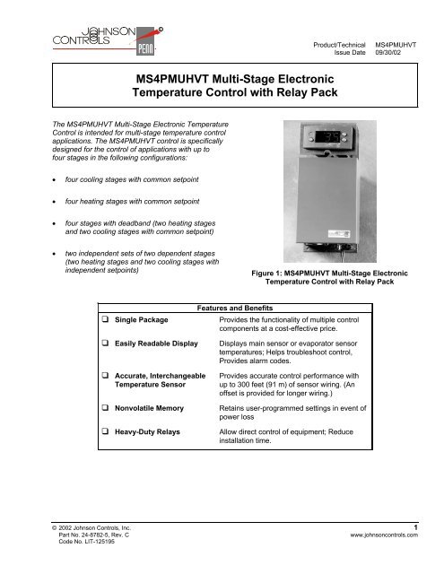
The <strong>MS4PMUHVT</strong> <strong>Multi</strong>-<strong>Stage</strong> <strong>Electronic</strong> <strong>Temperature</strong><br />
<strong>Control</strong> is intended for multi-stage temperature control<br />
applications. The <strong>MS4PMUHVT</strong> control is specifically<br />
designed for the control of applications <strong>with</strong> up to<br />
four stages in the following configurations:<br />
• four cooling stages <strong>with</strong> common setpoint<br />
• four heating stages <strong>with</strong> common setpoint<br />
• four stages <strong>with</strong> deadband (two heating stages<br />
and two cooling stages <strong>with</strong> common setpoint)<br />
• two independent sets of two dependent stages<br />
(two heating stages and two cooling stages <strong>with</strong><br />
independent setpoints)<br />
Figure 1: <strong>MS4PMUHVT</strong> <strong>Multi</strong>-<strong>Stage</strong> <strong>Electronic</strong><br />
<strong>Temperature</strong> <strong>Control</strong> <strong>with</strong> Relay Pack<br />
❑ Single Package<br />
Features and Benefits<br />
Provides the functionality of multiple control<br />
components at a cost-effective price.<br />
❑ Easily Readable Display<br />
❑ Accurate, Interchangeable<br />
<strong>Temperature</strong> Sensor<br />
❑ Nonvolatile Memory<br />
❑ Heavy-Duty Relays<br />
Displays main sensor or evaporator sensor<br />
temperatures; Helps troubleshoot control,<br />
Provides alarm codes.<br />
Provides accurate control performance <strong>with</strong><br />
up to 300 feet (91 m) of sensor wiring. (An<br />
offset is provided for longer wiring.)<br />
Retains user-programmed settings in event of<br />
power loss<br />
Allow direct control of equipment; Reduce<br />
installation time.<br />
© 2002 Johnson <strong>Control</strong>s, Inc. 1<br />
Part No. 24-8782-5, Rev. C<br />
www.johnsoncontrols.com<br />
Code No. LIT-125195
FCC Compliance Statement<br />
This equipment has been tested and found to<br />
comply <strong>with</strong> the limits for a Class A digital device<br />
pursuant to Part 15 of the FCC Rules. These limits<br />
are designed to provide reasonable protection<br />
against harmful interference when the equipment is<br />
operated in a commercial environment. This<br />
equipment generates, uses, and can radiate radio<br />
frequency energy and, if not installed and used in<br />
accordance <strong>with</strong> the instruction manual, may cause<br />
harmful interference to radio communications.<br />
Operation of this equipment in a residential area is<br />
likely to cause harmful interference, in which case<br />
the user will be required to correct the interference<br />
at his/her own expense.<br />
Canadian Compliance Statement<br />
This digital apparatus does not exceed the Class A<br />
limits for radio noise emissions from digital<br />
apparatus set out in the Radio Interference<br />
Regulations of the Canadian Department of<br />
Communications.<br />
Application<br />
IMPORTANT: The <strong>MS4PMUHVT</strong> <strong>Multi</strong>-<strong>Stage</strong><br />
<strong>Temperature</strong> <strong>Control</strong> is intended to control<br />
equipment under normal operating conditions.<br />
Where failure or malfunction of the <strong>MS4PMUHVT</strong><br />
control could lead to an abnormal operating<br />
condition that could cause personal injury or<br />
damage to the equipment or other property, other<br />
devices (limit or safety controls) or systems (alarm<br />
or supervisory systems) intended to warn of, or<br />
protect against, failure or malfunction of the<br />
<strong>MS4PMUHVT</strong> control must be incorporated into<br />
and maintained as part of the control system.<br />
The <strong>MS4PMUHVT</strong> control provides direct control in<br />
many applications:<br />
• cooling tower pump and/or fan control<br />
• rooftop heating or cooling units<br />
• boiler or pump control<br />
• space temperature control<br />
• compressor or chiller staging<br />
The <strong>MS4PMUHVT</strong> control has four heavy-duty<br />
relays. See electrical ratings in Table 6 for more<br />
information.<br />
Operation<br />
Mode Selection<br />
Mode Selection allows selection of one of several<br />
modes:<br />
• Direct mode for cooling applications<br />
• Reverse mode for heating applications<br />
• Deadband mode for applications requiring cooling<br />
and heating <strong>with</strong> a common setpoint and a<br />
deadband<br />
• Independent Setpoint mode for applications<br />
requiring cooling and heating <strong>with</strong> one setpoint for<br />
heating and a second (independent) setpoint for<br />
cooling<br />
<strong>Stage</strong> <strong>Control</strong><br />
Several settings define the control functions for the<br />
stages:<br />
• Setpoints and Differentials setting establish the<br />
temperature-control ranges.<br />
• Cycle Delays establish a set time interval between<br />
heating or cooling cycle restarts to avoid excessive<br />
cycling.<br />
• Soft Start controls the rate at which temperature<br />
approaches the Setpoint on power-up or when<br />
Binary Input Option 3 is selected. This feature is<br />
useful when starting equipment where merchandise<br />
in the controlled space needs to be slowly brought to<br />
the desired temperature (Setpoint). If this feature is<br />
used, the control activates up to four stages in<br />
succession to slowly bring the sensed temperature<br />
to the desired temperature (Setpoint) at the<br />
user-selected rate.<br />
Alarm Management<br />
Several settings define the control functions for alarms:<br />
• High and Low <strong>Temperature</strong> Alarms provide<br />
notification of temperatures that exceed<br />
user-designated high and low limits.<br />
• Alarm Time Delay keeps short-duration<br />
temperature changes from triggering an alarm.<br />
• Alarm Differential keeps the alarm from cycling<br />
rapidly on and off due to minor temperature<br />
fluctuations.<br />
• Alarm Codes assist in troubleshooting.<br />
2 <strong>MS4PMUHVT</strong> <strong>Multi</strong>-<strong>Stage</strong> <strong>Electronic</strong> <strong>Temperature</strong> <strong>Control</strong> <strong>with</strong> Relay Pack Product/Technical Bulletin
Binary Input Response<br />
Binary Input Function allows the user to select how<br />
the control responds to a binary input (switch) if the<br />
binary input contacts are open for a time (minutes)<br />
longer than the Binary Input Time Delay.<br />
Additional Features<br />
The <strong>MS4PMUHVT</strong> control uses several other<br />
settings to control specific features:<br />
• Keyboard Locking disables/enables change of<br />
the setpoint and other functions, reducing<br />
accidental or unauthorized changes of the<br />
control settings.<br />
• Self-test Procedure initiates a cycle of all<br />
outputs and tests all LEDs. See Initiating a<br />
Manual Self-Test.<br />
• Dual Sensor <strong>Temperature</strong> Reset resets the<br />
setpoint based on the difference between the<br />
Auxiliary <strong>Temperature</strong> Sensor (ATS) and the<br />
Setpoint to provide energy savings. See<br />
<strong>Temperature</strong> Reset.<br />
For additional information about control functions<br />
and how to program them, see Programming the<br />
<strong>Control</strong> and <strong>Control</strong> Functions.<br />
<strong>Control</strong> Module Front Panel<br />
The control module has an LED display and buttons<br />
for entering programming information and activating<br />
various features.<br />
The display has three LED digits and a minus<br />
indicator. It displays a temperature range from<br />
-40 to 176°F (-40 to 80°C) in increments of 1F° or<br />
C°. The display also features three relay status<br />
LEDs.<br />
• LED 1 indicates that the <strong>Stage</strong> 1 Relay is<br />
energized.<br />
• LED 2 indicates that the <strong>Stage</strong> 2 Relay is<br />
energized.<br />
• LED 3 indicates that the <strong>Stage</strong> 3 Relay is<br />
energized.<br />
Relay Status LEDs<br />
Up<br />
Button<br />
Installation<br />
See Mounting and Wiring for installation information.<br />
Dimensions<br />
3-5/8<br />
(92) 2-3/8<br />
(61)<br />
7-15/16<br />
(202)<br />
1-3/4<br />
(44)<br />
3<br />
(76)<br />
1-5/8<br />
(42)<br />
6<br />
(152)<br />
Figure 3: Relay Pack <strong>with</strong> Mounting Bracket<br />
Dimensions, in. (mm)<br />
2-3/4<br />
(70)<br />
3<br />
(75)<br />
2-5/16<br />
(58)<br />
1-3/8<br />
(35)<br />
2-11/16<br />
(68)<br />
1-1/8<br />
(28)<br />
Figure 4: <strong>Control</strong> Module Dimensions, in. (mm)<br />
1/4<br />
(6) 2<br />
(50)<br />
78-3/4<br />
(2000)<br />
Figure 5: A99BB-200C Sensor Dimensions, in. (mm)<br />
Enter<br />
Button<br />
Down<br />
Button<br />
Figure 2: <strong>Control</strong> Module Front Panel and<br />
Display<br />
<strong>MS4PMUHVT</strong> <strong>Multi</strong>-<strong>Stage</strong> <strong>Electronic</strong> <strong>Temperature</strong> <strong>Control</strong> <strong>with</strong> Relay Pack Product/Technical Bulletin 3
D4<br />
Mounting<br />
The <strong>MS4PMUHVT</strong> control is not position-sensitive<br />
but should be mounted for convenient wiring and<br />
adjustment. The <strong>MS4PMUHVT</strong> control may be<br />
mounted as a single unit or the control module and<br />
relay pack may be separated and mounted<br />
individually.<br />
Mounting the <strong>MS4PMUHVT</strong> <strong>Control</strong> as a<br />
Single Unit<br />
Before mounting the relay pack, ensure that there is<br />
sufficient space. Follow these steps to mount the<br />
relay pack:<br />
1. Hold the <strong>MS4PMUHVT</strong> control against the<br />
surface and use it as a template to trace the<br />
mounting slots.<br />
2. Drill holes for mounting screws in the holes<br />
indicated.<br />
3. Use three screws (No. 8 or No. 10 size) to<br />
mount the <strong>MS4PMUHVT</strong> control.<br />
2. Drill holes for mounting screws in the slots indicated.<br />
3. Use three screws (No. 8 or No. 10 size) to mount the<br />
relay pack.<br />
Mounting the <strong>Control</strong> Module<br />
Before mounting the control module, ensure that there is<br />
sufficient free space [at least 2-3/4 inches (70 mm)]<br />
behind the mounting surface. Follow these steps to<br />
mount the control module:<br />
1. Cut a hole 1-3/16 x 2-13/16 inches (29 x 71 mm).<br />
2. Remove the mounting clip from the control module.<br />
3. Insert the control module into the hole.<br />
4. Install the retaining clip and slide forward to adjust<br />
for tightness.<br />
5. Reconnect the wires on the terminals in the relay<br />
pack to the corresponding terminals on the control<br />
module. See Figures 7-9.<br />
Mounting the <strong>Control</strong> Module and Relay Pack<br />
Separately<br />
Mount the relay pack and the control module <strong>with</strong>in<br />
18 in. (46 cm) of each other.<br />
<strong>Control</strong><br />
Module<br />
Mounting<br />
Clip<br />
Removing the <strong>Control</strong> Module from the<br />
Relay Pack<br />
Follow these steps to separate the control module<br />
and the relay pack. See Figures 6-7.<br />
1. Locate the mounting clip that holds the control<br />
module to the mounting bracket on the relay<br />
pack.<br />
2. Squeeze the forward portion of the mounting clip<br />
together and slide the mounting clip back to<br />
remove the mounting clip from the back of the<br />
control module.<br />
3. Pull the control module out of the mounting<br />
bracket on the relay pack.<br />
4. Disconnect the wiring from the control module<br />
and the relay pack terminals V1, V2, O1, and<br />
O2. See Figures 7-9.<br />
Mounting the Relay Pack<br />
Before mounting the relay pack, ensure that there is<br />
sufficient space. Follow these steps to mount the<br />
relay pack:<br />
1. Hold the relay pack <strong>with</strong> mounting bracket<br />
against the surface and use as a template to<br />
trace the mounting slots.<br />
Figure 6: Removing the Mounting Clip and<br />
<strong>Control</strong> Module<br />
D3<br />
Figure 7: Relay Pack Terminal Positions on the<br />
Circuit Board<br />
V2 V1<br />
O1<br />
O2<br />
4 <strong>MS4PMUHVT</strong> <strong>Multi</strong>-<strong>Stage</strong> <strong>Electronic</strong> <strong>Temperature</strong> <strong>Control</strong> <strong>with</strong> Relay Pack Product/Technical Bulletin
Wiring<br />
!<br />
WARNING: Risk of Electric Shock.<br />
To avoid electric shock or damage to equipment,<br />
disconnect all power supplies before wiring any<br />
connections. More than one disconnect may be<br />
necessary to completely de-energize equipment.<br />
Wiring Sensors and Binary Inputs<br />
Wire the sensors and binary input (if used) as shown<br />
in Figures 8-9. The Sensor (S1 or S2) and Sensor<br />
Common (SC) wires are interchangeable when<br />
using the A99B temperature sensors. The binary<br />
input shares a common terminal <strong>with</strong> the sensors.<br />
Note: Black boxes indicate unused terminals.<br />
12VAC<br />
V1<br />
BLK<br />
V1<br />
V2<br />
WHT<br />
V2<br />
O1<br />
RED<br />
O1<br />
O2<br />
GRN<br />
O2<br />
Internal to <strong>Control</strong><br />
Binary<br />
Input<br />
(Switch)<br />
D<br />
S2<br />
Auxiliary<br />
<strong>Temperature</strong><br />
Sensor<br />
SC<br />
S1<br />
Sensor<br />
Common<br />
Main<br />
<strong>Temperature</strong><br />
Sensor<br />
Figure 8: Wiring the <strong>Control</strong> Module MS<br />
Loosen screw to open terminal;<br />
tighten screw to secure wiring.<br />
Table 1: Sensor Wire Size and Length<br />
Wire Size and Length<br />
18 AWG 20 AWG 22 AWG<br />
Offset<br />
300-599 ft 190-374 ft 120-239 ft 1 F°<br />
600-899 ft 375-564 ft 240-349 ft 2 F°<br />
900+ ft 565+ ft 350+ ft 3 F°<br />
165-329 m 105-204 m 65-129 m 1 C°<br />
330-495 m 205-310 m 130-195 m 2 C°<br />
Wiring the Relay Pack<br />
!<br />
WARNING: Risk of Electric Shock.<br />
To avoid electric shock or damage to equipment,<br />
disconnect all power supplies before wiring any<br />
connections. More than one disconnect may be<br />
necessary to completely de-energize equipment.<br />
See Figure 10 for arrangement of terminals on the<br />
terminal block in the relay pack. See Figures 11-12 for<br />
sample wiring diagrams. Follow these wiring guidelines:<br />
• All wiring must conform to the National Electrical<br />
Code and local regulations.<br />
• Use 14 AWG copper wire for motor loads up to 12 FLA<br />
and non-inductive loads up to 15 A.<br />
• Use 12 AWG copper wire <strong>with</strong> an insulation rating of<br />
75°C (minimum) for motor loads up to 16 FLA and<br />
non-inductive loads up to 20 A.<br />
V1 V2 O1 O2<br />
D<br />
S2 SC S1<br />
• Use wire no longer than 50 feet (15 m).<br />
• All circuits must have a common disconnect and be<br />
connected to the same pole of the disconnect.<br />
V1 V2 O1 O2<br />
D S2 SC S1<br />
Relay<br />
Pack<br />
Terminal<br />
Block<br />
Insert wiring here.<br />
Note: Black boxes indicate unused terminals.<br />
Figure 9: Rear View of the <strong>Control</strong> Module<br />
Use <strong>Temperature</strong> Sensor Offset to compensate for<br />
sensor leads longer than 300 ft (if °F is used) or<br />
165 m (if °C is used). See Table 1 and <strong>Temperature</strong><br />
Management Functions: <strong>Temperature</strong> Sensor Offset.<br />
Terminal<br />
Labels<br />
on<br />
Circuit<br />
Board<br />
NO1 CM1 L2 120 (Not NO2 CM2<br />
Used) NO4<br />
NO3<br />
NC1<br />
CM3<br />
NC3<br />
240<br />
NC2<br />
CM4<br />
Figure 10: Relay Pack Terminal Block<br />
NC4<br />
<strong>MS4PMUHVT</strong> <strong>Multi</strong>-<strong>Stage</strong> <strong>Electronic</strong> <strong>Temperature</strong> <strong>Control</strong> <strong>with</strong> Relay Pack Product/Technical Bulletin 5
L1<br />
Note: All circuits must have a common disconnect and be connected to the same pole of the disconnect.<br />
Internal to Relay Pack<br />
L2<br />
<strong>Control</strong> Relay 1 <strong>Control</strong> Relay 2 <strong>Control</strong> Relay 3 <strong>Control</strong> Relay 4<br />
240 120 NO1 CM1 NC1 NO2 CM2 NC2 NO3 CM3 NC3 NO4 CM4 NC4<br />
Load 1 Load 2 Load 3 Load 4<br />
Figure 11: Typical 240 VAC Relay Pack Wiring Connections<br />
120 VAC<br />
Note: All circuits must have a common disconnect and be connected to the same pole of the disconnect.<br />
Neutral<br />
Internal to Relay Pack<br />
<strong>Control</strong> Relay 1 <strong>Control</strong> Relay 2 <strong>Control</strong> Relay 3 <strong>Control</strong> Relay 4<br />
240 120 NO1 CM1 NC1 NO2 CM2 NC2 NO3 CM3 NC3 NO4 CM4 NC4<br />
Load 1 Load 2 Load 3 Load 4<br />
Figure 12: Typical 120 VAC Relay Pack Wiring Connections<br />
6 <strong>MS4PMUHVT</strong> <strong>Multi</strong>-<strong>Stage</strong> <strong>Electronic</strong> <strong>Temperature</strong> <strong>Control</strong> <strong>with</strong> Relay Pack Product/Technical Bulletin
Modes of Operation<br />
The <strong>MS4PMUHVT</strong> control performs temperature<br />
management for multi-stage applications. It can<br />
automatically adjust the setpoint to save energy,<br />
based on readings from the auxiliary temperature<br />
sensor and the function settings.<br />
The illustrations on the following pages show the<br />
modes of operation available on the <strong>MS4PMUHVT</strong><br />
control.<br />
Direct Mode (Cooling) and Reverse Mode (Heating)<br />
Direct mode is used for cooling applications. (See<br />
Figure 13.) Reverse mode is used for heating<br />
applications. (See Figure 14.) Where desirable, stages<br />
may overlap or have space between them.<br />
Setpoint is the desired temperature.<br />
In Direct Mode (cooling applications), when Setpoint is<br />
reached on a temperature drop, the Normally Open<br />
(N.O.) relay contacts open, ending the On cycle of<br />
<strong>Stage</strong> 1.<br />
In Reverse Mode (heating applications), when Setpoint<br />
is reached on a temperature rise the N.O. relay<br />
contacts open, ending the On cycle of <strong>Stage</strong> 1.<br />
Differential is the operational range of <strong>Stage</strong> 1.<br />
Setpoint 2 is the offset from Setpoint that activates<br />
<strong>Stage</strong> 2.<br />
Differential 2 is the operational range of <strong>Stage</strong> 2.<br />
Setpoint 3 is the offset from Setpoint that activates<br />
<strong>Stage</strong> 3.<br />
Differential 3 is the operational range of <strong>Stage</strong> 3.<br />
Setpoint 4 is the offset from Setpoint that activates<br />
<strong>Stage</strong> 4.<br />
Interstage Time Delay is the minimum amount of time<br />
between two successive stages when multiple stages<br />
are called for in rapid sequence.<br />
<strong>Temperature</strong><br />
On<br />
<strong>Stage</strong><br />
1<br />
Interstage<br />
Time<br />
Delay<br />
Off<br />
<strong>Temperature</strong><br />
On<br />
Off<br />
<strong>Stage</strong><br />
1<br />
On<br />
<strong>Stage</strong><br />
2<br />
Off<br />
Differential<br />
Setpoint<br />
Interstage<br />
Time<br />
Delay<br />
On<br />
<strong>Stage</strong><br />
3<br />
Off<br />
Differential 2<br />
Interstage<br />
Time<br />
Delay<br />
Setpoint 2<br />
(Offset from<br />
Setpoint)<br />
<strong>Stage</strong><br />
4<br />
Off<br />
Differential 3<br />
Differential 4<br />
Setpoint 4<br />
(Offset from<br />
Setpoint)<br />
Setpoint 3<br />
(Offset from<br />
Setpoint)<br />
Figure 13: Direct Mode (Cooling)<br />
Differential<br />
On<br />
Interstage<br />
Time<br />
Delay<br />
Setpoint<br />
Off<br />
<strong>Stage</strong><br />
2<br />
Setpoint 2<br />
(Offset from<br />
Setpoint)<br />
Setpoint 3<br />
(Offset from<br />
Setpoint)<br />
Differential 2<br />
On<br />
Interstage<br />
Time<br />
Delay<br />
Off<br />
<strong>Stage</strong><br />
3<br />
Differential 3<br />
Off<br />
<strong>Stage</strong><br />
4<br />
On<br />
Interstage<br />
Time<br />
Delay<br />
Time<br />
Setpoint 4<br />
(Offset from<br />
Setpoint)<br />
Differential 4<br />
Time<br />
Figure 14: Reverse Mode (Heating)<br />
<strong>MS4PMUHVT</strong> <strong>Multi</strong>-<strong>Stage</strong> <strong>Electronic</strong> <strong>Temperature</strong> <strong>Control</strong> <strong>with</strong> Relay Pack Product/Technical Bulletin 7
Deadband Mode<br />
Deadband mode is used for applications requiring<br />
cooling and heating. Where desirable, stages may<br />
overlap or have space between them. See Figure 15.<br />
Setpoint is the desired temperature.<br />
Setpoint 2 is width of the deadband, which is centered<br />
on Setpoint.<br />
In Direct Mode (cooling applications), the N.O. relay<br />
contacts open, ending the On cycle when<br />
Setpoint + (1/2 Setpoint 2) is reached on a<br />
temperature drop.<br />
In Reverse Mode (heating applications), the N.O. relay<br />
contacts open, ending the On cycle when Setpoint -<br />
(1/2 Setpoint 2) is reached on a temperature rise.<br />
Differential is the operational range of <strong>Stage</strong> 1.<br />
Differential 2 is the operational range of <strong>Stage</strong> 2.<br />
Setpoint 3 is the offset from the low end of the<br />
deadband that activates <strong>Stage</strong> 3.<br />
Differential 3 is the operational range of <strong>Stage</strong> 3.<br />
Setpoint 4 is the offset from the high end of the<br />
deadband that activates <strong>Stage</strong> 4.<br />
Differential 4 is the operational range of <strong>Stage</strong> 4.<br />
Interstage Time Delay is the minimum amount of time<br />
between two successive stages when multiple stages<br />
are called for in rapid sequence.<br />
<strong>Temperature</strong><br />
Interstage<br />
Time Delay<br />
On<br />
Cooling<br />
<strong>Stage</strong> 4<br />
Differential 4<br />
On<br />
<strong>Stage</strong> 2<br />
Differential 2<br />
Off<br />
Setpoint 4<br />
(Offset from <strong>Stage</strong> 2)<br />
Off<br />
Setpoint<br />
Off<br />
Setpoint + (1/2 Setpoint 2)<br />
Setpoint - (1/2 Setpoint 2)<br />
Setpoint 2 (Deadband)<br />
(Centered on Setpoint)<br />
<strong>Stage</strong> 1<br />
Differential<br />
Off<br />
Setpoint 3<br />
(Offset from <strong>Stage</strong> 1)<br />
On<br />
<strong>Stage</strong> 3<br />
Differential 3<br />
Heating<br />
On<br />
Interstage<br />
Time Delay<br />
Time<br />
Figure 15: Deadband Mode<br />
8 <strong>MS4PMUHVT</strong> <strong>Multi</strong>-<strong>Stage</strong> <strong>Electronic</strong> <strong>Temperature</strong> <strong>Control</strong> <strong>with</strong> Relay Pack Product/Technical Bulletin
Independent Setpoint Mode<br />
Independent Setpoint mode is used for applications<br />
requiring cooling and heating. Where desirable, stages<br />
may overlap or have space between them. See<br />
Figure 16.<br />
Setpoint is the desired heating temperature. It is the<br />
basis for the reverse stages.<br />
In Reverse mode (heating applications), when Setpoint<br />
is reached on a temperature rise, the N.O. relay<br />
contacts open, ending the On cycle.<br />
Setpoint cannot be set higher than Setpoint 2, nor can<br />
Setpoint 2 be set lower than Setpoint. If overlapping<br />
adjustment is attempted, the setting that is not being<br />
adjusted will adopt the value of the setting that is being<br />
adjusted.<br />
Differential is the operational range of <strong>Stage</strong> 1.<br />
Setpoint 2 the desired cooling temperature<br />
programmed by the user. It is the basis for the direct<br />
stages.<br />
In Direct mode (cooling applications), when Setpoint is<br />
reached on a temperature drop, the N.O. relay<br />
contacts open, ending the On cycle.<br />
Differential 2 is the operational range of <strong>Stage</strong> 2.<br />
Setpoint 3 is the offset from Setpoint that activates<br />
<strong>Stage</strong> 3.<br />
Differential 3 is the operational range of <strong>Stage</strong> 3.<br />
Setpoint 4 is the offset from Setpoint 2 that activates<br />
<strong>Stage</strong> 4.<br />
Differential 4 is the operational range of <strong>Stage</strong> 4.<br />
Interstage Time Delay is the minimum amount of time<br />
between two successive stages when multiple stages<br />
are called for in rapid sequence.<br />
<strong>Temperature</strong><br />
Interstage<br />
Time Delay<br />
Cooling<br />
<strong>Stage</strong> 4<br />
Differential 4<br />
<strong>Stage</strong> 2<br />
Differential 2<br />
Setpoint 4<br />
Setpoint<br />
<strong>Stage</strong> 1<br />
Differential<br />
Setpoint 3<br />
<strong>Stage</strong> 3<br />
Differential 3<br />
Heating<br />
Interstage<br />
Time Delay<br />
Time<br />
Figure 16: Independent Setpoint Mode<br />
<strong>MS4PMUHVT</strong> <strong>Multi</strong>-<strong>Stage</strong> <strong>Electronic</strong> <strong>Temperature</strong> <strong>Control</strong> <strong>with</strong> Relay Pack Product/Technical Bulletin 9
Programming the <strong>Control</strong><br />
Use this section to program the control module. After<br />
programming, the control module retains its<br />
programmed settings, even in the event of a power<br />
failure or power-down.<br />
Using the <strong>Control</strong> Module<br />
During normal operation, the display shows the main<br />
sensor temperature. See Figure 2.<br />
• Press Up or Down repeatedly to display the main<br />
sensor temperature, auxiliary sensor temperature<br />
and the binary input status.<br />
• Press Enter to display the Setpoint value.<br />
After 15 seconds of inactivity, the display returns to<br />
main sensor temperature.<br />
Unlocking or Locking Access to Programming<br />
1. In sequence, press and hold Enter, Up,<br />
and Down.<br />
2. Hold these buttons until “- - -” displays.<br />
3. Continue holding until the main sensor<br />
temperature displays (approximately<br />
10 seconds).<br />
Selecting the Mode of Operation<br />
1. At the same time, press and hold<br />
Enter and Down for approximately<br />
three seconds.<br />
2. Press Up or Down until the display<br />
code for the desired mode displays:<br />
4d = Direct mode (cooling)<br />
4r = Reverse mode (heating)<br />
4b = Deadband mode (both)<br />
4i = Independent Setpoint mode (both)<br />
3. Press Enter to save the new setting.<br />
Changing the Setpoint in Independent Setpoint<br />
Mode and Changing Other Function Settings in<br />
All Modes<br />
1. Press and hold Enter for about 10<br />
seconds. The display changes to HY.<br />
(The display shows S1 if in Mode 4i.)<br />
2. Press Up or Down until the desired<br />
function displays. See Table 4 and<br />
<strong>Control</strong> Functions.<br />
3. Press Enter. The function’s existing<br />
value displays.<br />
4. Press Up or Down until the desired<br />
setting value displays.<br />
5. Press Enter to save the new value.<br />
After 10 seconds of inactivity, the<br />
display returns to normal operation.<br />
Note: If Enter is not pressed, the new value is not<br />
saved, and the control reverts to the previous saved<br />
value.<br />
Initiating a Manual Self-Test<br />
IMPORTANT: Disconnect controlled loads<br />
before running the self-test procedure. Reconnect<br />
controlled loads and cycle power to resume normal<br />
operation.<br />
1. In sequence, press and hold Up and<br />
then Down.<br />
2. Hold for five seconds.<br />
Note: If Enter is not pressed, the new mode of<br />
operation is not saved, and the control reverts to the<br />
previous mode of operation.<br />
Changing the Setpoint in Direct, Reverse, and<br />
Deadband Modes<br />
1. Press and hold Enter for<br />
approximately three seconds.<br />
2. Release Enter when the new Setpoint<br />
value displays.<br />
3. Press Up or Down to display the new<br />
Setpoint value.<br />
4. Press Enter to save the new setting.<br />
Note: If Enter is not pressed, the new Setpoint<br />
value is not saved, and the control reverts to the<br />
previous Setpoint value.<br />
10 <strong>MS4PMUHVT</strong> <strong>Multi</strong>-<strong>Stage</strong> <strong>Electronic</strong> <strong>Temperature</strong> <strong>Control</strong> <strong>with</strong> Relay Pack Product/Technical Bulletin
<strong>Control</strong> Functions<br />
<strong>Temperature</strong> Management Functions<br />
SI (Displays in Mode 4i only) Setpoint is the primary<br />
temperature setting (°F or °C) programmed by the<br />
user. For information on function in each mode, see<br />
Modes of Operation.<br />
S2, S3, S4 Setpoint 2, Setpoint 3, Setpoint 4 depend<br />
on the mode used. For information on function in each<br />
mode, see Modes of Operation.<br />
30 o F<br />
<strong>Temperature</strong><br />
Setpoint<br />
Sensed<br />
<strong>Temperature</strong><br />
HI, H2, H3, H4 Differentials are the difference (F° or<br />
C°) between the value at which an output is switched<br />
Off and the value at which an output is switched On<br />
(relay contacts closing and opening, initiating or<br />
ending an On cycle). For information on function in<br />
each mode, see Modes of Operation.<br />
HL, LL High and Low Setpoint Stops are<br />
temperature values (°F or °C) that define how high or<br />
low the primary Setpoint may be adjusted. Setpoint<br />
stops deter unauthorized or accidental overadjustment<br />
of Setpoint.<br />
On<br />
Off<br />
On<br />
Off<br />
Load Demand<br />
Output Status<br />
20 o F<br />
Output Status<br />
(up to four stages)<br />
Time (Minutes)<br />
2 4 6 8 10 12 14 16 18<br />
Figure 18: Soft Start<br />
Soft Start Example:<br />
<strong>Temperature</strong> = 20°<br />
Setpoint = 30°<br />
Soft start = 2 minutes<br />
Rate of Increase =<br />
Soft start x (setpoint – sensor reading)<br />
20<br />
On<br />
Off<br />
Cycle Delay<br />
Time<br />
Figure 17: Cycle Delay<br />
Cc Cycle Delay, Cooling establishes the minimum<br />
time in minutes between two subsequent On cycles of<br />
cooling (direct) stages. See Figure 17.<br />
CH Cycle Delay, Heating establishes the minimum<br />
time in minutes between two subsequent On cycles of<br />
heating (reverse) stages. See Figure 17.<br />
iS Interstage Time Delay is the minimum amount of<br />
time between two successive stages when multiple<br />
stages are called for in rapid sequence.<br />
rt Soft Start controls the rate at which the controlled<br />
temperature is allowed to approach Setpoint on power<br />
up, both initially and when the binary input is<br />
configured as remote shutoff. The setting is<br />
minutes/temperature units, such as minutes/F°. See<br />
Figure 18.<br />
<strong>Control</strong>led temperature increases by 1° every<br />
two minutes, until the setpoint temperature is<br />
reached. To go from 20° to 30° takes 20 minutes.<br />
So <strong>Temperature</strong> Sensor Offset allows compensation<br />
for temperature differences between actual and<br />
displayed temperature, such as when using long<br />
sensor leads. See Table 1 to determine the<br />
temperature value to compensate for long sensor lead<br />
extensions.<br />
Un <strong>Temperature</strong> Units Used allows selection of<br />
Fahrenheit or Celsius temperature scale.<br />
PU Display Refresh Rate establishes the time delay<br />
(seconds) between updates of the temperature<br />
display.<br />
Lc, Uc Heating Reset and Cooling Reset are<br />
automatic shifts of the setpoint, based on the<br />
temperature at the Auxiliary <strong>Temperature</strong> Sensor<br />
(ATS). See <strong>Temperature</strong> Reset for more information.<br />
NC Non-compensated Band establishes the<br />
temperature range (F° or C°) over which reset does<br />
not take place.<br />
<strong>MS4PMUHVT</strong> <strong>Multi</strong>-<strong>Stage</strong> <strong>Electronic</strong> <strong>Temperature</strong> <strong>Control</strong> <strong>with</strong> Relay Pack Product/Technical Bulletin 11
Alarm Management Functions<br />
AH High <strong>Temperature</strong> Alarm establishes the<br />
temperature relative to Setpoint (F° or C°) at which the<br />
control goes into a high temperature alarm condition.<br />
(The temperature value is added to the Setpoint.)<br />
AL Low <strong>Temperature</strong> Alarm establishes the<br />
temperature relative to Setpoint (F° or C°) at which the<br />
control goes into a low temperature alarm condition.<br />
(The temperature value is subtracted from the<br />
Setpoint.)<br />
AH, AL High and Low <strong>Temperature</strong> Alarms are<br />
disabled during defrost and for 20 minutes after the<br />
defrost cycle. These alarms are also disabled for<br />
20 minutes after startup.<br />
Ad Alarm Differential establishes the difference (F°<br />
or C°) between the alarm activation temperature and<br />
the alarm deactivation temperature.<br />
Alarm Differential Example - Cooling Applications:<br />
Setpoint = 40°F<br />
High <strong>Temperature</strong> Alarm = 15F°<br />
Alarm Differential = 2F°<br />
When the room temperature exceeds 55°F<br />
(40+15=55°F) for a time greater than the alarm<br />
time delay setting, the alarm message is<br />
displayed; however, it will reset after the<br />
temperature drops below 53°F (40+15-2=53°F).<br />
At Alarm Time Delay establishes the time delay<br />
(minutes) between reaching a high or low temperature<br />
alarm condition and displaying an alarm message on<br />
the display. This function reduces alarm oscillation and<br />
nuisance alarms caused by temperatures that<br />
temporarily exceed alarm setpoint temperatures.<br />
Binary Input Functions<br />
iF Binary Input Mode allows selection of how the<br />
Normally Closed (N.C.) binary input activates the<br />
stage control contacts.<br />
Binary Input Mode can be disabled or can provide one<br />
of three predetermined responses to the binary input.<br />
(If a set of stage control contacts are used to control<br />
an external alarm, this function should be disabled.)<br />
• Shutoff and Alarm Signaling - If the binary input<br />
contact is open for a time longer than that set<br />
through the Binary Input Time Delay, the stage<br />
control contacts are switched Off, and an alarm<br />
message (A1) is displayed.<br />
• Setback - If the binary input contact is open for a<br />
time longer than that set through the Binary Input<br />
Time Delay, the setpoints are shifted by Setback.<br />
Reverse setpoints (heating) decrease. Direct<br />
setpoints (cooling) increase.<br />
• Remote Shutoff of the outputs. - If the binary<br />
input contact is open for a time longer than that set<br />
through the Binary Input Time Delay, the stage<br />
control contacts are switched Off.<br />
id Binary Input Time Delay establishes the time<br />
delay (minutes) between the binary input signal<br />
reaching the control and activation of the response<br />
selected by Binary Input Mode.<br />
Sb Setback determines the value of the Setpoint shift<br />
when the binary input is open and Setback is the<br />
response selected by Binary Input Mode.<br />
12 <strong>MS4PMUHVT</strong> <strong>Multi</strong>-<strong>Stage</strong> <strong>Electronic</strong> <strong>Temperature</strong> <strong>Control</strong> <strong>with</strong> Relay Pack Product/Technical Bulletin
<strong>Temperature</strong> Reset<br />
The control module uses non-compensated band<br />
and heating reset or cooling reset to automatically<br />
adjust the setpoint. These functions appear only when<br />
the Auxiliary <strong>Temperature</strong> Sensor (ATS) is connected.<br />
If the ATS is connected after the control module is<br />
powered up, the control module must be powered<br />
down and then powered up for these functions to<br />
appear.<br />
Non-Compensated Band<br />
Non-Compensated Band (NCB) is a temperature<br />
differential from setpoint. Within the range of this<br />
differential, variations in the ATS temperature do not<br />
cause a temperature reset. See Heating Reset and<br />
Cooling Reset for more information.<br />
Note: When Deadband mode or Independent<br />
Setpoint mode are used, NCB is the same for heating<br />
stages and cooling stages.<br />
Heating Reset<br />
When (Setpoint – ATS <strong>Temperature</strong>) > NCB, the<br />
control adjusts the heating setpoint by the following<br />
amount:<br />
[ATS Temp. – (Setpoint – NCB)] / Heating Reset<br />
Heating reset only affects the setpoint for heating<br />
stages.<br />
Heating<br />
Reset<br />
Example<br />
Step 1<br />
Step 2<br />
Setpoint = 70°F<br />
ATS <strong>Temperature</strong> = 42°F<br />
NCB = 20F°<br />
Heating Reset = 2F°<br />
[ATS <strong>Temperature</strong> – (setpoint–NCB)] / heating<br />
reset = [42 – (70 – 20)]/2 = -4<br />
setpoint + reset<br />
70 + (-4) = 66<br />
Setpoint is reset to 66°F to save energy. See<br />
Figure 19.<br />
1°<br />
Heating<br />
Reset<br />
Setpoint<br />
Process<br />
<strong>Temperature</strong><br />
Sensor<br />
70°<br />
Cooling Reset<br />
When (ATS <strong>Temperature</strong> - Setpoint) > NCB, the<br />
control adjusts the cooling setpoint by the following<br />
amount:<br />
[ATS – (Setpoint + NCB)] / Cooling Reset<br />
Cooling reset only affects the setpoint for cooling<br />
stages.<br />
Cooling<br />
Reset<br />
Example<br />
Step 1<br />
Setpoint = 70°F<br />
ATS <strong>Temperature</strong>= 92°F<br />
NCB = 10F°<br />
Cooling Reset = 2F°<br />
ATS <strong>Temperature</strong> – (setpoint + NCB) / cooling<br />
reset = [92 – (70 + 10)] / 2 = 6<br />
Step 2 setpoint + reset<br />
70 + 6 = 76<br />
Setpoint is reset to 76°F to save energy. See<br />
Figure 20.<br />
Process<br />
<strong>Temperature</strong><br />
Sensor<br />
76°<br />
70°<br />
70°<br />
Setpoint<br />
Non-<br />
Compensated<br />
Band<br />
NCB = 10°<br />
1°<br />
Cooling<br />
Reset<br />
80° 92°<br />
Auxiliary <strong>Temperature</strong> Sensor (ATS)<br />
Figure 20: Cooling Reset<br />
Non-<br />
Compensated<br />
Band<br />
NCB = 20°<br />
66°<br />
42° 50° 70°<br />
Auxiliary <strong>Temperature</strong> Sensor (ATS)<br />
Figure 19: Heating Reset<br />
<strong>MS4PMUHVT</strong> <strong>Multi</strong>-<strong>Stage</strong> <strong>Electronic</strong> <strong>Temperature</strong> <strong>Control</strong> <strong>with</strong> Relay Pack Product/Technical Bulletin 13
Table 2: Function Settings in Order of Programming in <strong>Control</strong> Module<br />
Display Code Function Useable Setting Range and Unit Value Factory-Set<br />
Values<br />
4d = Direct<br />
4r = Reverse<br />
4b = Deadband<br />
4i = Independent<br />
setpoints<br />
Modes of Operation<br />
4d = Direct<br />
4r = Reverse<br />
4b = Deadband<br />
4i = Independent setpoints<br />
4d<br />
SI (Mode 4i only) Setpoint 4d, 4r, 4b = -40 to 99°F (-40 to 80°C)<br />
4i = Low Setpoint Stop to High Setpoint Stop<br />
HI Differential 1 1 to 9F° (1 to 9C°) 5 (F°)<br />
S2 ∆ Setpoint 2 4d, 4r = 1 to 40F° (1 to 40C°)<br />
4b = 2 to 40F° (2 to 40C°)<br />
4i = Low Setpoint Stop to High Setpoint Stop<br />
—<br />
5 (F°)<br />
H2 Differential 2 1 to 9F° (1 to 9C°) 5 (F°)<br />
S3 ∆ Setpoint 3 1 to 40F° (1 to 40C°) 5 (F°)<br />
H3 Differential 3 1 to 9F° (1 to 9C°) 5 (F°)<br />
S4 ∆ Setpoint 4 1 to 40F° (1 to 40C°) 5 (F°)<br />
H4 Differential 4 1 to 9F° (1 to 9C°) 5 (F°)<br />
LL Low Setpoint Stop -40°F (-40°C) to High Setpoint Stop 32 (°F)<br />
HL High Setpoint Stop Low Setpoint Stop to 99°F (80°C) 90 (°F)<br />
Cc Cycle Delay, Cooling 0 to 9 minutes 2 (minutes)<br />
CH Cycle Delay, Heating 0 to 9 minutes 0 (minutes)<br />
rt Soft Start 0 to 99 minutes/degrees 10<br />
AH High <strong>Temperature</strong> Alarm 0 to 50F° (0 to 50C°) 15 (F°)<br />
AL Low <strong>Temperature</strong> Alarm -50 to 0F° (-50 to 0C°) -15 (F°)<br />
Ad Alarm Differential 1 to 9F° (1 to 9C°) 5 (F°)<br />
At Alarm Time Delay 0 to 99 minutes 15 (minutes)<br />
So <strong>Temperature</strong> Sensor Offset -20 to 20F° (-20 to 20C°) 0 (F°)<br />
Un <strong>Temperature</strong> Units Used 0 = °C<br />
1 = °F<br />
PU Display Refresh Rate 1 to 99 seconds 1 (second)<br />
iF Binary Input Mode 0 = No Response to Binary Input<br />
1 = Shutoff and Alarm Signaling<br />
2 = Setback Mode<br />
3 = Remote Shutoff<br />
1 (°F)<br />
Sb Setback -20 to 20F° (-20 to 20C°) 10 (F°)<br />
0 (no response)<br />
id Binary Input Time Delay 0 to 99 minutes 0 (minutes)<br />
iS Interstage Time Delay 3 to 90 seconds 3 (seconds)<br />
Lc Heating Reset 0 to 6°/ ° 4<br />
Uc Cooling Reset 0 to 6°/ ° 4<br />
NC Non-Compensated Band 0 to 20F° (0 to 20C°) 8<br />
Note: <strong>Temperature</strong> Reset Functions (Heating Reset, Cooling Reset, Non-compensated Band) are only enabled after the<br />
auxiliary sensor is installed and power is cycled.<br />
14 <strong>MS4PMUHVT</strong> <strong>Multi</strong>-<strong>Stage</strong> <strong>Electronic</strong> <strong>Temperature</strong> <strong>Control</strong> <strong>with</strong> Relay Pack Product/Technical Bulletin
Alarm and Fault Display Codes<br />
These alarm and fault codes flash on the LED display<br />
when the control detects the following faults:<br />
Table 3: Alarm Display Codes (Flashing)<br />
Display<br />
Meaning<br />
Code<br />
F1<br />
A1<br />
OF<br />
HI<br />
LO<br />
Indicates an open or shorted main temperature<br />
sensor.<br />
Binary input is open for longer than the Binary Input<br />
Time Delay and Binary Input Mode Option 1 is<br />
selected.<br />
Binary input is open and Binary Input Mode<br />
Option 3 selected.<br />
Main sensor temperature has reached or exceeded<br />
the High <strong>Temperature</strong> Alarm value.<br />
Main sensor temperature has reached or fallen<br />
below the Low <strong>Temperature</strong> Alarm value.<br />
System Status<br />
Alarm message displays. Correct problem and cycle<br />
power to reset control.<br />
<strong>Control</strong> output is switched off; alarm message displays.<br />
Correct the condition to reset.<br />
<strong>Control</strong> output is switched off. Close the digital input to<br />
reset.<br />
Alarm message displays. Correct the condition to reset.<br />
Alarm message displays. Correct the condition to reset.<br />
EE Program failure Alarm message displays, other outputs off. Replace<br />
control.<br />
Table 4: Status Codes (Steady)<br />
Status Code Indicates:<br />
On<br />
Auxiliary temperature sensor (S2) is not connected or, if it is connected, the sensor (or binary input) is<br />
open or shorted.<br />
OF<br />
Binary input is closed.<br />
Ordering Information<br />
Table 5: Ordering Information<br />
Item Code Description Shipping weight<br />
<strong>MS4PMUHVT</strong>-11C Relay pack temperature control <strong>with</strong> two A99B sensors 2.9 lb (1320 g)<br />
MS4PM12C-11C Replacement control module for use in relay pack only 1.6 lb (726 g)<br />
RP4MSUHV-1C Relay pack <strong>with</strong>out control module 2.3 lb (1060 g)<br />
A99BB-200C Sensor, cable length: 6-1/2 ft (2 m) 0.13 lb (60 g)<br />
Repair and Replacement<br />
Field repair of the control should not be made. In case<br />
of a defective or improperly functioning control, please<br />
check <strong>with</strong> your nearest Johnson <strong>Control</strong>s/PENN<br />
representative.<br />
Relay Electrical Ratings<br />
Relay Ratings in Table 6 are for ambient temperatures<br />
in the range -40 to 111°F (-40 to 44°C). Derate<br />
electrical ratings 3.45% per 1F° in the range<br />
111 to 140°F. Derate electrical ratings 6.25% per 1C°<br />
in the range 44 to 60°C.<br />
<strong>MS4PMUHVT</strong> <strong>Multi</strong>-<strong>Stage</strong> <strong>Electronic</strong> <strong>Temperature</strong> <strong>Control</strong> <strong>with</strong> Relay Pack Product/Technical Bulletin 15
Table 6: SPDT Relay Electrical Ratings<br />
Single-Phase Ratings<br />
24 VAC 120 VAC 208 VAC 240 VAC<br />
Horsepower Rating — 1/3 3/4 1<br />
AC Full Load Amperes — 7.2 7.6 8<br />
AC Locked Rotor Amperes — 43.2 45.6 48<br />
Non-Inductive Amperes — 8 8 8<br />
Pilot Duty (VA) 50 325 625 750<br />
Technical Specifications<br />
Product<br />
Electrical Ratings See Table 6.<br />
Frequency<br />
<strong>MS4PMUHVT</strong> <strong>Multi</strong>-<strong>Stage</strong> <strong>Electronic</strong> <strong>Temperature</strong> <strong>Control</strong> <strong>with</strong> Relay Pack<br />
60 Hz<br />
Power Requirements 120/240 VAC ±10%<br />
Power Consumption<br />
Accuracy<br />
Sensor Input Range<br />
10 VA @ 120/240 VAC<br />
±1.8F° (±1C°)<br />
A99B Sensor Cable 6-1/2 ft (2 m)<br />
Ambient Operating<br />
Conditions<br />
Ambient Storage<br />
Conditions<br />
-40 to 158°F (-40 to +70°C)<br />
<strong>MS4PMUHVT</strong>-11C:<br />
MS4PM12C-11C:<br />
RP4MSUHV-1C:<br />
<strong>MS4PMUHVT</strong>-11C:<br />
MS4PM12C-11C:<br />
RP4MSUHV-1C:<br />
Dimensions (H x W x D) See Figures 3-5.<br />
Agency Listings<br />
Emissions Compliance FCC (US)<br />
DOC (Canada)<br />
Shipping Weight See Table 5.<br />
UL Listed (US), File SA516, CCN SDFY<br />
UL Listed (Canada), File SA516, CCN SDFY7<br />
+14 to +140°F (-10 to +60°C); 0 to 95 % RH (noncondensing)<br />
+14 to +140°F (-10 to +60°C); 0 to 95 % RH (noncondensing)<br />
-40 to +140°F (-10 to +60°C); 0 to 95 % RH (noncondensing)<br />
-22 to +176°F (-30 to +80°C); 0 to 95 % RH (noncondensing)<br />
-22 to +176°F (-30 to +80°C); 0 to 95 % RH (noncondensing)<br />
-40 to +185°F (-40 to +85°C); 0 to 95 % RH (noncondensing)<br />
The performance specifications are nominal and conform to acceptable industry standards. For application at conditions beyond these<br />
specifications, consult Johnson <strong>Control</strong>s/Penn Application Engineering at 1-800-275-5676. Johnson <strong>Control</strong>s, Inc. shall not be liable for<br />
damages resulting from misapplication or misuse of its products.<br />
<strong>Control</strong>s Group<br />
507 E. Michigan Street<br />
P.O. Box 423<br />
Milwaukee, WI 53201<br />
Published in U.S.A.<br />
www.johnsoncontrols.com<br />
16 <strong>MS4PMUHVT</strong> <strong>Multi</strong>-<strong>Stage</strong> <strong>Electronic</strong> <strong>Temperature</strong> <strong>Control</strong> <strong>with</strong> Relay Pack Product/Technical Bulletin