MS4PMUHVT Multi-Stage Electronic Temperature Control with ...
MS4PMUHVT Multi-Stage Electronic Temperature Control with ...
MS4PMUHVT Multi-Stage Electronic Temperature Control with ...

Create successful ePaper yourself
Turn your PDF publications into a flip-book with our unique Google optimized e-Paper software.
D4<br />
Mounting<br />
The <strong>MS4PMUHVT</strong> control is not position-sensitive<br />
but should be mounted for convenient wiring and<br />
adjustment. The <strong>MS4PMUHVT</strong> control may be<br />
mounted as a single unit or the control module and<br />
relay pack may be separated and mounted<br />
individually.<br />
Mounting the <strong>MS4PMUHVT</strong> <strong>Control</strong> as a<br />
Single Unit<br />
Before mounting the relay pack, ensure that there is<br />
sufficient space. Follow these steps to mount the<br />
relay pack:<br />
1. Hold the <strong>MS4PMUHVT</strong> control against the<br />
surface and use it as a template to trace the<br />
mounting slots.<br />
2. Drill holes for mounting screws in the holes<br />
indicated.<br />
3. Use three screws (No. 8 or No. 10 size) to<br />
mount the <strong>MS4PMUHVT</strong> control.<br />
2. Drill holes for mounting screws in the slots indicated.<br />
3. Use three screws (No. 8 or No. 10 size) to mount the<br />
relay pack.<br />
Mounting the <strong>Control</strong> Module<br />
Before mounting the control module, ensure that there is<br />
sufficient free space [at least 2-3/4 inches (70 mm)]<br />
behind the mounting surface. Follow these steps to<br />
mount the control module:<br />
1. Cut a hole 1-3/16 x 2-13/16 inches (29 x 71 mm).<br />
2. Remove the mounting clip from the control module.<br />
3. Insert the control module into the hole.<br />
4. Install the retaining clip and slide forward to adjust<br />
for tightness.<br />
5. Reconnect the wires on the terminals in the relay<br />
pack to the corresponding terminals on the control<br />
module. See Figures 7-9.<br />
Mounting the <strong>Control</strong> Module and Relay Pack<br />
Separately<br />
Mount the relay pack and the control module <strong>with</strong>in<br />
18 in. (46 cm) of each other.<br />
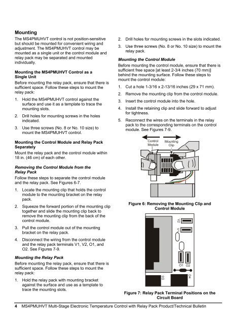
<strong>Control</strong><br />
Module<br />
Mounting<br />
Clip<br />
Removing the <strong>Control</strong> Module from the<br />
Relay Pack<br />
Follow these steps to separate the control module<br />
and the relay pack. See Figures 6-7.<br />
1. Locate the mounting clip that holds the control<br />
module to the mounting bracket on the relay<br />
pack.<br />
2. Squeeze the forward portion of the mounting clip<br />
together and slide the mounting clip back to<br />
remove the mounting clip from the back of the<br />
control module.<br />
3. Pull the control module out of the mounting<br />
bracket on the relay pack.<br />
4. Disconnect the wiring from the control module<br />
and the relay pack terminals V1, V2, O1, and<br />
O2. See Figures 7-9.<br />
Mounting the Relay Pack<br />
Before mounting the relay pack, ensure that there is<br />
sufficient space. Follow these steps to mount the<br />
relay pack:<br />
1. Hold the relay pack <strong>with</strong> mounting bracket<br />
against the surface and use as a template to<br />
trace the mounting slots.<br />
Figure 6: Removing the Mounting Clip and<br />
<strong>Control</strong> Module<br />
D3<br />
Figure 7: Relay Pack Terminal Positions on the<br />
Circuit Board<br />
V2 V1<br />
O1<br />
O2<br />
4 <strong>MS4PMUHVT</strong> <strong>Multi</strong>-<strong>Stage</strong> <strong>Electronic</strong> <strong>Temperature</strong> <strong>Control</strong> <strong>with</strong> Relay Pack Product/Technical Bulletin