MS4PMUHVT Multi-Stage Electronic Temperature Control with ...
MS4PMUHVT Multi-Stage Electronic Temperature Control with ...
MS4PMUHVT Multi-Stage Electronic Temperature Control with ...

You also want an ePaper? Increase the reach of your titles
YUMPU automatically turns print PDFs into web optimized ePapers that Google loves.
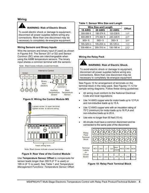
Wiring<br />
!<br />
WARNING: Risk of Electric Shock.<br />
To avoid electric shock or damage to equipment,<br />
disconnect all power supplies before wiring any<br />
connections. More than one disconnect may be<br />
necessary to completely de-energize equipment.<br />
Wiring Sensors and Binary Inputs<br />
Wire the sensors and binary input (if used) as shown<br />
in Figures 8-9. The Sensor (S1 or S2) and Sensor<br />
Common (SC) wires are interchangeable when<br />
using the A99B temperature sensors. The binary<br />
input shares a common terminal <strong>with</strong> the sensors.<br />
Note: Black boxes indicate unused terminals.<br />
12VAC<br />
V1<br />
BLK<br />
V1<br />
V2<br />
WHT<br />
V2<br />
O1<br />
RED<br />
O1<br />
O2<br />
GRN<br />
O2<br />
Internal to <strong>Control</strong><br />
Binary<br />
Input<br />
(Switch)<br />
D<br />
S2<br />
Auxiliary<br />
<strong>Temperature</strong><br />
Sensor<br />
SC<br />
S1<br />
Sensor<br />
Common<br />
Main<br />
<strong>Temperature</strong><br />
Sensor<br />
Figure 8: Wiring the <strong>Control</strong> Module MS<br />
Loosen screw to open terminal;<br />
tighten screw to secure wiring.<br />
Table 1: Sensor Wire Size and Length<br />
Wire Size and Length<br />
18 AWG 20 AWG 22 AWG<br />
Offset<br />
300-599 ft 190-374 ft 120-239 ft 1 F°<br />
600-899 ft 375-564 ft 240-349 ft 2 F°<br />
900+ ft 565+ ft 350+ ft 3 F°<br />
165-329 m 105-204 m 65-129 m 1 C°<br />
330-495 m 205-310 m 130-195 m 2 C°<br />
Wiring the Relay Pack<br />
!<br />
WARNING: Risk of Electric Shock.<br />
To avoid electric shock or damage to equipment,<br />
disconnect all power supplies before wiring any<br />
connections. More than one disconnect may be<br />
necessary to completely de-energize equipment.<br />
See Figure 10 for arrangement of terminals on the<br />
terminal block in the relay pack. See Figures 11-12 for<br />
sample wiring diagrams. Follow these wiring guidelines:<br />
• All wiring must conform to the National Electrical<br />
Code and local regulations.<br />
• Use 14 AWG copper wire for motor loads up to 12 FLA<br />
and non-inductive loads up to 15 A.<br />
• Use 12 AWG copper wire <strong>with</strong> an insulation rating of<br />
75°C (minimum) for motor loads up to 16 FLA and<br />
non-inductive loads up to 20 A.<br />
V1 V2 O1 O2<br />
D<br />
S2 SC S1<br />
• Use wire no longer than 50 feet (15 m).<br />
• All circuits must have a common disconnect and be<br />
connected to the same pole of the disconnect.<br />
V1 V2 O1 O2<br />
D S2 SC S1<br />
Relay<br />
Pack<br />
Terminal<br />
Block<br />
Insert wiring here.<br />
Note: Black boxes indicate unused terminals.<br />
Figure 9: Rear View of the <strong>Control</strong> Module<br />
Use <strong>Temperature</strong> Sensor Offset to compensate for<br />
sensor leads longer than 300 ft (if °F is used) or<br />
165 m (if °C is used). See Table 1 and <strong>Temperature</strong><br />
Management Functions: <strong>Temperature</strong> Sensor Offset.<br />
Terminal<br />
Labels<br />
on<br />
Circuit<br />
Board<br />
NO1 CM1 L2 120 (Not NO2 CM2<br />
Used) NO4<br />
NO3<br />
NC1<br />
CM3<br />
NC3<br />
240<br />
NC2<br />
CM4<br />
Figure 10: Relay Pack Terminal Block<br />
NC4<br />
<strong>MS4PMUHVT</strong> <strong>Multi</strong>-<strong>Stage</strong> <strong>Electronic</strong> <strong>Temperature</strong> <strong>Control</strong> <strong>with</strong> Relay Pack Product/Technical Bulletin 5