MicroLab User Guide for MicroLog and ... - Fourier Systems
MicroLab User Guide for MicroLog and ... - Fourier Systems
MicroLab User Guide for MicroLog and ... - Fourier Systems

You also want an ePaper? Increase the reach of your titles
YUMPU automatically turns print PDFs into web optimized ePapers that Google loves.
INNOVATIVE<br />
MONITORING<br />
SOLUTIONS<br />
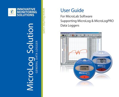
<strong>MicroLog</strong> Solution<br />
GENERAL DATA LOGGER<br />
www.fourtec.com<br />
<strong>User</strong> <strong>Guide</strong><br />
For <strong>MicroLab</strong> Software<br />
Supporting <strong>MicroLog</strong> & <strong>MicroLog</strong>PRO<br />
Data Loggers
<strong>MicroLab</strong> <strong>User</strong> <strong>Guide</strong> <strong>for</strong> the<br />
<strong>MicroLog</strong> <strong>and</strong> <strong>MicroLog</strong>PRO<br />
Second Edition<br />
First Print<br />
April 2011<br />
© fourtec - <strong>Fourier</strong> Technologies Ltd.
Technical Support:<br />
support@fourtec.com<br />
www.fourtec.com
Contents<br />
Using the <strong>Guide</strong> ...................................................................... 1<br />
Compliance with FDA Title 21 CFR Part 11............................ 3<br />
Chapter 1 <strong>MicroLog</strong> ................................................................ 4<br />
1.1. Getting Started.......................................................... 5<br />
1.2. Working with <strong>MicroLog</strong> ............................................. 6<br />
1.2.1. Data Displays......................................................... 6<br />
Current data........................................................... 6<br />
Minimum <strong>and</strong> maximum values.............................. 7
Status messages ..................................................10<br />
1.2.2. Working Modes.....................................................12<br />
1.2.3. <strong>MicroLog</strong>’s Connections .......................................13<br />
Connect <strong>MicroLog</strong> to a computer..........................14<br />
Connect <strong>MicroLog</strong> to an external sensor ..............16<br />
1.2.4. Sleep Mode ..........................................................16<br />
1.2.5. Replacing the Battery ...........................................19<br />
Chapter 2 <strong>MicroLog</strong>PRO .......................................................21<br />
2.1. Overview .................................................................22<br />
2.2. Getting Started ........................................................23<br />
2.3. Working with <strong>MicroLog</strong>PRO ....................................24<br />
2.3.1. Data Displays .......................................................24
Current Data ........................................................ 24<br />
Minimum <strong>and</strong> Maximum Values........................... 24<br />
Status Messages ................................................. 28<br />
2.3.2. Working Modes.................................................... 32<br />
2.3.3. Alarm Levels ........................................................ 33<br />
2.3.4. <strong>MicroLog</strong>PRO’s Connections............................... 34<br />
Connecting <strong>MicroLog</strong>PRO to PC Serial Port........ 34<br />
Connecting <strong>MicroLog</strong>PRO to PC USB Port ......... 36<br />
Connecting <strong>MicroLog</strong>PRO to an External Sensor 36<br />
2.3.5. Sending Data to an Infrared Printer ..................... 37<br />
Sending Min/Max Values ..................................... 37<br />
Sending all of the Data......................................... 38<br />
2.3.6. Battery Level........................................................ 39<br />
2.3.7. Replacing the Battery........................................... 42<br />
Chapter 3 Working with the <strong>MicroLab</strong> Software.................... 45
3.1. Installation ...............................................................46<br />
3.1.1. System Requirements ..........................................46<br />
3.1.2. Installing the Software ..........................................47<br />
3.1.3. Installing the USB Driver ......................................47<br />
3.2. Overview .................................................................51<br />
3.2.1. Getting Started .....................................................52<br />
Downloading Data ................................................52<br />
Saving Data..........................................................53<br />
Opening Files .......................................................55<br />
Displaying Properties............................................55<br />
Printing a Graph ...................................................56<br />
Printing a Table ....................................................56<br />
3.2.2. Viewing the Data ..................................................58<br />
Display Options ....................................................58
Graph .................................................................. 58<br />
Table .................................................................. 59<br />
Data Map ............................................................. 60<br />
The Cursor........................................................... 62<br />
Zooming <strong>and</strong> Panning.......................................... 63<br />
Cropping the Data................................................ 68<br />
Formatting the Graph........................................... 69<br />
Displaying Alarm Levels....................................... 70<br />
Changing the Temperature Units......................... 70<br />
Adding Annotations to the Graph......................... 71<br />
Exporting Data to Excel ....................................... 73<br />
Export File Settings.............................................. 74<br />
Copying the Graph as a Picture........................... 75<br />
Viewing more than one data set on the graph ..... 75<br />
3.2.3. Programming the Data Logger............................. 78<br />
Setup .................................................................. 78
Saving Setup ........................................................87<br />
Starting Data Recording .......................................88<br />
Stopping Data Recording .....................................89<br />
3.2.4. Sensor Calibration ................................................89<br />
3.2.5. Defining a Custom Sensor....................................95<br />
3.2.6. Communication Options .......................................98<br />
Setting IR Printing Format (<strong>for</strong> the <strong>MicroLog</strong>PRO<br />
only) ..................................................................98<br />
Communication Setup ..........................................99<br />
Automatic Daily Download..................................101<br />
3.2.7. Analysis Tools ....................................................101<br />
Setting the Analysis Tools Parameters...............101<br />
Histogram ...........................................................102<br />
Pasteurization.....................................................105<br />
Statistics .............................................................105<br />
3.2.8. Toolbar Buttons ..................................................107
Main (Upper) Toolbar......................................... 107<br />
Graph (Lower) Toolbar....................................... 110<br />
Chapter 4 External Sensors................................................ 112<br />
4.1. Temperature -50 °C to 100 °C/ 110 °C (Thermistorbased).............................................................................<br />
112<br />
4.2. Voltage Sensor ..................................................... 114<br />
4.3. Current Sensor ..................................................... 115<br />
4.4. pH Sensor............................................................. 116<br />
Specifications...................................................................... 117<br />
<strong>MicroLog</strong> ......................................................................... 117
<strong>MicroLog</strong>PRO..................................................................121<br />
Software ..........................................................................126<br />
Appendix: Figures ...............................................................128<br />
Index ...........................................................................129
Using the <strong>Guide</strong><br />
Using the <strong>Guide</strong><br />
This user guide describes how to operate the <strong>MicroLog</strong> 8-bit<br />
<strong>and</strong> <strong>MicroLog</strong>PRO 10-bit data loggers, each one controlled<br />
by the <strong>MicroLab</strong> software. These loggers are used to monitor<br />
temperature <strong>and</strong> humidity in a variety of applications, such<br />
as perishable goods <strong>and</strong> controlled environments. Each<br />
logger can also be connected to external sensors in order to<br />
monitor additional parameters. Each logger comes in two<br />
models:<br />
<strong>MicroLog</strong><br />
• EC600 with internal temperature sensor, <strong>and</strong><br />
one external input<br />
• EC650 with internal temperature <strong>and</strong> humidity<br />
sensor, <strong>and</strong> one external input<br />
1
Using the <strong>Guide</strong><br />
<strong>MicroLog</strong>PRO<br />
• EC700 with internal temperature sensor, <strong>and</strong><br />
one external input<br />
• EC750 with internal temperature <strong>and</strong> humidity<br />
sensor, <strong>and</strong> one external input<br />
Chapter 1 - Overview <strong>for</strong> operating the <strong>MicroLog</strong> data logger<br />
Chapter 2 - Overview <strong>for</strong> operating the <strong>MicroLog</strong> data logger<br />
Chapter 3 - Overview <strong>for</strong> running the <strong>MicroLab</strong> software,<br />
which support the <strong>MicroLog</strong> <strong>and</strong> <strong>MicroLog</strong>PRO data loggers.<br />
Chapter 4 – Specifications of the external sensors<br />
connecting to the data loggers<br />
Specifications – Spec sheets <strong>for</strong> the data loggers <strong>and</strong><br />
software<br />
2
Using the <strong>Guide</strong><br />
Compliance with FDA Title 21 CFR Part 11<br />
To achieve compliance with FDA Title 21 CFR Part 11, use<br />
fourtec’s software package: <strong>MicroLab</strong> together with DatPass.<br />
The DatPass software is fourtec’s administration software.<br />
Among other features, it defines the users that can log onto<br />
the <strong>MicroLab</strong> software, their passwords <strong>and</strong> the digital<br />
signatures the users are permitted to sign data within<br />
electronic records (files). DatPass also maintains an audit<br />
trail to keep track of all action per<strong>for</strong>med within the system.<br />
The system is secured with a serial port dongle, without<br />
which the <strong>MicroLab</strong> <strong>and</strong> DatPass software packages will not<br />
operate.<br />
3
Chapter 1<br />
<strong>MicroLog</strong><br />
Chapter 1<br />
<strong>MicroLog</strong><br />
4
<strong>MicroLog</strong> Chapter 1<br />
<strong>MicroLog</strong> can be used as a st<strong>and</strong>-alone device to monitor<br />
temperature <strong>and</strong> humidity levels. All viewing, exporting <strong>and</strong><br />
printing of the data obtained is done with just two keys.<br />
<strong>MicroLog</strong> continuously displays the most recent recordings,<br />
along with the maximum <strong>and</strong> minimum values <strong>for</strong> a selected<br />
time interval. <strong>User</strong>s can also define minimum <strong>and</strong> maximum<br />
alarm levels <strong>for</strong> a specific shipment, <strong>and</strong> the display screen<br />
will begin to flash if either level is breached.<br />
The data stored by <strong>MicroLog</strong> can be downloaded to any<br />
computer <strong>for</strong> further viewing <strong>and</strong> analysis using the <strong>MicroLab</strong><br />
software, <strong>and</strong> can be exported to a spreadsheet.<br />
1.1. Getting Started<br />
In order to save battery life, <strong>MicroLog</strong> is shipped in Stop<br />
Mode. This means that be<strong>for</strong>e you can start recording, you<br />
5
Chapter 1<br />
<strong>MicroLog</strong><br />
must first connect <strong>MicroLog</strong> to the PC <strong>and</strong> set it up with the<br />
accompanying software. To set up <strong>MicroLog</strong> with the<br />
<strong>MicroLab</strong> software, refer to section Chapter 3.<br />
Once <strong>MicroLog</strong> receives the setup comm<strong>and</strong>, it begins<br />
logging the data immediately.<br />
1.2. Working with <strong>MicroLog</strong><br />
1.2.1. Data Displays<br />
Current data<br />
When <strong>MicroLog</strong> is recording, the data from the sensors is<br />
displayed alternately. The data obtained from external<br />
sensors is displayed with a small EXT symbol.<br />
6
<strong>MicroLog</strong> Chapter 1<br />
When <strong>MicroLog</strong> stores the data, the LCD display briefly<br />
changes to a “double dash” (- -) symbol.<br />
Minimum <strong>and</strong> maximum values<br />
You can display minimum <strong>and</strong> maximum values <strong>for</strong> any hour<br />
from the last 24 hours <strong>and</strong> <strong>for</strong> any day from the last 30 days<br />
by using <strong>MicroLog</strong>’s left <strong>and</strong> right keys:<br />
Viewing Min. <strong>and</strong> Max Values in the Last 1-24 Hours<br />
1. Select a<br />
time period<br />
by<br />
pressing<br />
the right<br />
key on the<br />
<strong>MicroLog</strong><br />
7
Chapter 1<br />
<strong>MicroLog</strong><br />
<strong>MicroLog</strong>. The LCD will begin displaying<br />
the hour number, ranging from hours 1 to<br />
24. Once you’ve reached the desired time<br />
period, release the right key.<br />
2. Once you’ve released the right key,<br />
<strong>MicroLog</strong> will display the Min <strong>and</strong> Max<br />
values logged by the sensors during the<br />
selected time period.<br />
3. (Optional) Once the left key is released,<br />
<strong>MicroLog</strong> will send an IR signal of the Min<br />
<strong>and</strong> Max values <strong>for</strong> the selected time<br />
period. To receive a printout of this data,<br />
simply point the <strong>MicroLog</strong> to the IR printer<br />
(HP portable printer – model No. 82240B).<br />
8
<strong>MicroLog</strong> Chapter 1<br />
Viewing Min. <strong>and</strong> Max Values <strong>for</strong> the last 1-30 Days<br />
1. Select a time period by pressing the left<br />
key on the<br />
<strong>MicroLog</strong>.<br />
The LCD<br />
will display<br />
the day<br />
number,<br />
ranging<br />
from days<br />
<strong>MicroLog</strong><br />
1 to 30. Once you’ve reached the desired<br />
time period, release the left key.<br />
9
Chapter 1<br />
<strong>MicroLog</strong><br />
2. Once the left key is released, <strong>MicroLog</strong> will<br />
display the Min <strong>and</strong> Max values of the<br />
sensors <strong>for</strong> the selected time period.<br />
3. (Optional) Once the left key is released,<br />
the <strong>MicroLog</strong> will send an IR signal of the<br />
Min <strong>and</strong> Max values <strong>for</strong> the selected time<br />
period. To receive a printout of this data,<br />
simply point <strong>MicroLog</strong> to the IR printer (HP<br />
portable printer – model No. 82240B).<br />
Status messages<br />
When both the left <strong>and</strong> right keys are pressed<br />
simultaneously, the <strong>MicroLog</strong> LCD will display <strong>MicroLog</strong>’s<br />
status. This will also “wake up” the device, a step necessary<br />
10
<strong>MicroLog</strong> Chapter 1<br />
<strong>for</strong> its communication with a computer. The status messages<br />
include:<br />
<strong>MicroLog</strong><br />
– Run<br />
– Cyclic Run<br />
11
Chapter 1<br />
<strong>MicroLog</strong><br />
– Timer Run<br />
– Stop Mode<br />
– Downloading data to a PC<br />
1.2.2. Working Modes<br />
<strong>MicroLog</strong> is always set in one of the 4 possible modes:<br />
Stop – <strong>MicroLog</strong> is idle <strong>and</strong> is not recording.<br />
12
<strong>MicroLog</strong> Chapter 1<br />
Run – <strong>MicroLog</strong> is recording data. It will stop recording<br />
automatically when its memory is full (16,000 recordings).<br />
Cyclic Run – Same as Run, but <strong>MicroLog</strong> will record over<br />
the old data when the memory is full, beginning with the<br />
earliest data recording.<br />
Timer Run – <strong>MicroLog</strong> can be configured to start recording<br />
at a predetermined time. When <strong>MicroLog</strong> is set <strong>for</strong> such a<br />
run, its status is set to Timer Run. Once <strong>MicroLog</strong> starts<br />
recording, its status changes to either Run or Cyclic Run,<br />
depending on the desired configuration.<br />
1.2.3. <strong>MicroLog</strong>’s Connections<br />
Note: <strong>MicroLog</strong> ships with a rubber plug that covers the rear<br />
socket. The plug protects the socket from moisture. Unless<br />
you are using the socket leave the plug in.<br />
13
Chapter 1<br />
<strong>MicroLog</strong><br />
Connect <strong>MicroLog</strong> to a computer<br />
For this you will need a serial communication cable (catalog<br />
number DT058).<br />
The serial communication cable<br />
ends with a type D 9-pin female<br />
plug. Plug this in to any free COM<br />
port on your computer.<br />
14
<strong>MicroLog</strong> Chapter 1<br />
The other end of the<br />
serial communication<br />
cable ends with a small<br />
black flat plug. Plug<br />
this end into the socket<br />
at the back of the<br />
<strong>MicroLog</strong>.<br />
Note that the socket<br />
has three pins, with<br />
one further away from<br />
the other two (Figure<br />
4). Take care to plug<br />
the cable in correctly.<br />
Figure 1: Connecting <strong>MicroLog</strong><br />
15
Chapter 1<br />
<strong>MicroLog</strong><br />
Connect <strong>MicroLog</strong> to an external sensor<br />
Use the same PC connection socket to connect to an<br />
external sensor (see Figure 4).<br />
Note that the socket has three pins, with one further away<br />
from the other two (Figure 4). Take care to plug the cable in<br />
correctly.<br />
1.2.4. Sleep Mode<br />
The <strong>MicroLog</strong> battery's maximum lifespan is approximately<br />
1.5 years. This long battery life is achieved by <strong>MicroLog</strong><br />
putting itself "to sleep" between recordings, or after 4<br />
minutes goes by without communication with the computer.<br />
While sleeping the data logger consumes a minimal amount<br />
of power.<br />
16
<strong>MicroLog</strong> Chapter 1<br />
<strong>MicroLog</strong> "wakes up" every second <strong>for</strong> a very short time (a<br />
few micro-seconds) to check if one of the keys has been<br />
pressed or if there is a message coming in from the<br />
computer. This is the reason you have to press <strong>and</strong> hold a<br />
key <strong>for</strong> at least two seconds be<strong>for</strong>e a status message<br />
appears.<br />
If you use high sampling rates, the <strong>MicroLog</strong> battery’s<br />
lifespan will be considerably shorter (see Figure 5).<br />
17
Chapter 1<br />
<strong>MicroLog</strong><br />
Duration of working in monthes<br />
30<br />
25<br />
20<br />
15<br />
10<br />
5<br />
0<br />
12.1<br />
5.9<br />
0.8<br />
16.4<br />
21.5<br />
23.3<br />
24.1<br />
EC650<br />
EC600<br />
0 5 10 15 20<br />
Minutes between samples<br />
24.4<br />
24.6<br />
18<br />
Figure 2: <strong>MicroLog</strong> battery life<br />
Note: The figures on the graph refer to <strong>MicroLog</strong> usage without daily<br />
download <strong>and</strong> without viewing min/max values on <strong>MicroLog</strong>'s display
1.2.5. Replacing the Battery<br />
<strong>MicroLog</strong> Chapter 1<br />
Warning: The back cover of the <strong>MicroLog</strong> contains a special<br />
compartment <strong>for</strong> the fragile humidity sensor. When removing<br />
or replacing the cover, be careful not to harm the sensor.<br />
Humidity<br />
sensor<br />
Humidity<br />
sensor<br />
+<br />
Figure 3: Replacing the battery<br />
19
Chapter 1<br />
<strong>MicroLog</strong><br />
Note: The <strong>MicroLog</strong> uses a 1/2AA 3.6V lithium battery.<br />
20<br />
1. Unfasten the four screws on the back of<br />
the <strong>MicroLog</strong>.<br />
2. Carefully remove the back cover<br />
3. Replace the battery, <strong>and</strong> be sure to insert<br />
the new battery into the correct<br />
corresponding polarities (look <strong>for</strong> the “+”<br />
symbol next to the positive terminal)<br />
4. Carefully reposition the electronic board on<br />
<strong>MicroLog</strong>’s back cover <strong>and</strong> make sure that<br />
the humidity sensor is placed in its<br />
compartment.<br />
5. Refasten the four screws on the back of<br />
the <strong>MicroLog</strong>.
<strong>MicroLog</strong>PRO Chapter 2<br />
Chapter 2<br />
<strong>MicroLog</strong>PRO<br />
21
Chapter 2<br />
<strong>MicroLog</strong>PRO<br />
2.1. Overview<br />
<strong>MicroLog</strong>PRO can be used as a st<strong>and</strong>alone device to<br />
monitor temperature <strong>and</strong> humidity levels. All viewing,<br />
exporting <strong>and</strong> printing of the data obtained is done with just<br />
two keys. <strong>MicroLog</strong>PRO continuously displays the most<br />
recent recordings, along with the maximum <strong>and</strong> minimum<br />
values <strong>for</strong> a selected time interval. <strong>User</strong>s can also define<br />
minimum <strong>and</strong> maximum alarm levels <strong>for</strong> a specific shipment,<br />
<strong>and</strong> the display screen will show alarm icons if either level is<br />
breached.<br />
The data stored by <strong>MicroLog</strong>PRO can be downloaded to any<br />
computer <strong>for</strong> further viewing <strong>and</strong> analysis using the <strong>MicroLab</strong><br />
software, <strong>and</strong> can be exported to an Excel spreadsheet.<br />
The data can also be easily transmitted to an infrared printer.<br />
22
2.2. Getting Started<br />
<strong>MicroLog</strong>PRO Chapter 2<br />
In order to save battery life, <strong>MicroLog</strong>PRO is shipped in Stop<br />
Mode. This means that be<strong>for</strong>e you can start recording, you<br />
must first connect <strong>MicroLog</strong>PRO to the PC <strong>and</strong> set it up with<br />
the accompanying <strong>MicroLab</strong> software. To set up<br />
<strong>MicroLog</strong>PRO with the <strong>MicroLab</strong> software, refer to section<br />
Chapter 3.<br />
Once <strong>MicroLog</strong>PRO receives the setup comm<strong>and</strong>, it begins<br />
logging the data immediately or waits <strong>for</strong> a predefined time to<br />
start logging.<br />
23
Chapter 2<br />
<strong>MicroLog</strong>PRO<br />
2.3. Working with <strong>MicroLog</strong>PRO<br />
2.3.1. Data Displays<br />
Current Data<br />
When <strong>MicroLog</strong>PRO is recording, the data from the sensors<br />
is alternately displayed. The data obtained from external<br />
sensors is displayed with a small EXT icon.<br />
When <strong>MicroLog</strong>PRO stores the data, the LCD display briefly<br />
changes to a four dash (- - - -) symbol.<br />
Minimum <strong>and</strong> Maximum Values<br />
You can display minimum <strong>and</strong> maximum values, ranging<br />
from the last<br />
24
<strong>MicroLog</strong>PRO Chapter 2<br />
1 - 24 hours <strong>and</strong> from the last 1 - 30 days, by using<br />
<strong>MicroLog</strong>PRO’s left <strong>and</strong> right buttons:<br />
Viewing Min. <strong>and</strong> Max Values in the last 1-24 Hours<br />
1. Select a time period by<br />
pressing the right button<br />
on the <strong>MicroLog</strong>PRO.<br />
The LCD will begin<br />
displaying the hour<br />
number, ranging from 1<br />
to 24 hours. Once you’ve<br />
reached the desired time<br />
period, release the right<br />
button.<br />
25
Chapter 2<br />
<strong>MicroLog</strong>PRO<br />
2. Once you’ve released the right button, <strong>MicroLog</strong>PRO<br />
will display the Min <strong>and</strong> Max values logged by the<br />
sensors during the selected time period.<br />
3. Once the button is released, <strong>MicroLog</strong>PRO will also<br />
send an IR signal of a predefined data options. To<br />
receive a printout of this data, simply point the<br />
<strong>MicroLog</strong>PRO to the IR printer (HP portable printer –<br />
model No. 82240B).<br />
26
<strong>MicroLog</strong>PRO Chapter 2<br />
Viewing Min. <strong>and</strong> Max Values <strong>for</strong> the last 1-30 Days<br />
1. Select a time period<br />
by pressing the left<br />
button on the<br />
<strong>MicroLog</strong>PRO. The<br />
LCD will display the<br />
day number, ranging<br />
from 1 to 30 days.<br />
Once you’ve reached<br />
the desired time<br />
period, release the<br />
left button.<br />
27
Chapter 2<br />
<strong>MicroLog</strong>PRO<br />
2. Once the left button is released, <strong>MicroLog</strong>PRO will<br />
display the Min <strong>and</strong> Max values of the sensors <strong>for</strong> the<br />
selected time period.<br />
3. Once the left button is released, <strong>MicroLog</strong>PRO will also<br />
send an IR signal of a predefined data options. To<br />
receive a printout of this data, simply point the<br />
<strong>MicroLog</strong>PRO to the IR printer (HP portable printer –<br />
model No. 82240B).<br />
Status Messages<br />
When both the left <strong>and</strong> right buttons are pressed<br />
simultaneously, the <strong>MicroLog</strong>PRO LCD will display<br />
<strong>MicroLog</strong>PRO’s current working mode <strong>and</strong> version.<br />
28
<strong>MicroLog</strong>PRO Chapter 2<br />
After releasing these buttons, <strong>MicroLog</strong>PRO will display its<br />
internal software version (if the letter H appears next to the<br />
version number, this means that this model includes a built-in<br />
humidity sensor as well as a temperature sensor)<br />
The status messages include:<br />
– Run<br />
29
Chapter 2<br />
<strong>MicroLog</strong>PRO<br />
– Cyclic Run<br />
– Timer Run<br />
– Stop Mode<br />
– Downloading data to a PC<br />
30
<strong>MicroLog</strong>PRO Chapter 2<br />
– Push to Run<br />
– Sending data to an IR printer<br />
31
Chapter 2<br />
<strong>MicroLog</strong>PRO<br />
2.3.2. Working Modes<br />
<strong>MicroLog</strong>PRO is always set in one of 5 possible modes:<br />
Stop – <strong>MicroLog</strong>PRO is idle <strong>and</strong> is not recording.<br />
Run – <strong>MicroLog</strong>PRO is recording data. It will stop recording<br />
automatically when its memory has reached full capacity<br />
(52,000 samples with one sensor).<br />
Cyclic Run – Similar to Run mode, but <strong>MicroLog</strong>PRO will<br />
record over the old data when the memory is full, beginning<br />
with the earliest data recording.<br />
Timer Run – <strong>MicroLog</strong>PRO can be configured to start<br />
recording at a predetermined time. When <strong>MicroLog</strong>PRO is<br />
set <strong>for</strong> such a run, its status is set to Timer Run.<br />
Push to Run – <strong>MicroLog</strong>PRO will only begin logging data<br />
when the user pushes either the left or right buttons.<br />
32
<strong>MicroLog</strong>PRO Chapter 2<br />
2.3.3. Alarm Levels<br />
<strong>MicroLog</strong>PRO displays an alarm notification whenever any<br />
alarm level is exceeded.<br />
AL-L – A sensor’s reading is lower than its low alarm level.<br />
AL-H – A sensor’s reading is higher than its high alarm level.<br />
The alarm notification remains until the next time you view<br />
Min/Max values or download data to a PC.<br />
To learn how to set alarm levels, refer to page 78.<br />
33
Chapter 2<br />
<strong>MicroLog</strong>PRO<br />
2.3.4. <strong>MicroLog</strong>PRO’s Connections<br />
Note: <strong>MicroLog</strong>PRO ships with a rubber plug that covers the<br />
rear socket. The plug protects the socket from moisture.<br />
Unless you are using the socket, leave the plug in.<br />
Connecting <strong>MicroLog</strong>PRO to PC Serial Port<br />
For this you will need a Serial communication cable (catalog<br />
number DT058).<br />
The serial communication cable<br />
ends with a type D 9-pin female<br />
plug. Plug this in to any free COM<br />
port on your computer.<br />
34
<strong>MicroLog</strong>PRO Chapter 2<br />
The other end of the<br />
serial communication<br />
cable ends with a small<br />
black flat plug. Plug this<br />
end into the socket at the<br />
back of the<br />
<strong>MicroLog</strong>PRO.<br />
Note that the socket has<br />
three pins, with one<br />
further away from the<br />
other two. Take care to<br />
plug the cable in<br />
correctly.<br />
Figure 4: Connecting<br />
<strong>MicroLog</strong>PRO<br />
35
Chapter 2<br />
<strong>MicroLog</strong>PRO<br />
Connecting <strong>MicroLog</strong>PRO to PC USB Port<br />
With <strong>MicroLog</strong>PRO model EC750 only, you may connect the<br />
logger to the PC USB port using the mini USB cable socket<br />
on the side of the logger.<br />
Once you connect the logger to the PC you will be required<br />
to install the logger USB driver in order <strong>for</strong> the <strong>MicroLab</strong><br />
software to detect the logger. Refer to page 47.<br />
Connecting <strong>MicroLog</strong>PRO to an External<br />
Sensor<br />
Use the same PC connection socket to connect to an<br />
external sensor (see Figure 4).<br />
Note that the socket has three pins, with one further away<br />
from the other two (Figure 4). Take care to plug the cable in<br />
correctly.<br />
36
<strong>MicroLog</strong>PRO Chapter 2<br />
2.3.5. Sending Data to an Infrared Printer<br />
<strong>MicroLog</strong>PRO can send data to an infrared printer. There are<br />
two <strong>for</strong>mats of data sending. In one <strong>for</strong>mat, <strong>MicroLog</strong>PRO<br />
sends the minimum <strong>and</strong> maximum values of a selected time<br />
period up to the last 30 days. The second <strong>for</strong>mat enables<br />
you to send all data up to 80 rows of data. Programming<br />
<strong>MicroLog</strong>PRO to the desired mode is done via <strong>MicroLab</strong><br />
software (refer to page 98).<br />
Sending Min/Max Values<br />
1. Select the time period as in viewing the min/max values<br />
(refer to page 24)<br />
2. Release the button.<br />
3. Point <strong>MicroLog</strong>PRO to the IR printer (HP portable printer<br />
– model No. 82240B).<br />
37
Chapter 2<br />
<strong>MicroLog</strong>PRO<br />
The printout includes <strong>MicroLog</strong>PRO’s serial number <strong>and</strong><br />
comment, alarm levels, the minimum <strong>and</strong> maximum values<br />
<strong>for</strong> each sensor <strong>and</strong> the time duration of any breaching of the<br />
alarm levels.<br />
Sending all of the Data<br />
1. Point <strong>MicroLog</strong>PRO to the IR printer.<br />
2. Push any button on the <strong>MicroLog</strong>PRO logger.<br />
The printout includes <strong>MicroLog</strong>PRO’s serial number <strong>and</strong><br />
comment, alarm levels, <strong>and</strong> a table of pre defined number of<br />
rows including time column, sensors readings columns <strong>and</strong> a<br />
column with an asterisk <strong>for</strong> each time any of the alarm levels<br />
was exceeded.<br />
38
<strong>MicroLog</strong>PRO Chapter 2<br />
2.3.6. Battery Level<br />
<strong>MicroLog</strong>PRO displays a battery level indicator at the top<br />
right corner of the LCD screen – a battery icon with bars in it.<br />
Three bars indicate a full battery <strong>and</strong> an empty icon indicates<br />
a low battery that needs replacing.<br />
The <strong>MicroLog</strong>PRO battery’s maximum lifespan is<br />
approximately 2 years. This long battery life is achieved by<br />
<strong>MicroLog</strong>PRO putting itself to sleep between recordings, or<br />
after 4 minutes goes by without communication with the<br />
computer. While in sleep mode, the data logger consumes a<br />
minimal amount of power.<br />
<strong>MicroLog</strong>PRO wakes up every second <strong>for</strong> a few microseconds<br />
in order to check if one of the buttons has been<br />
pressed or if there is an incoming message from the<br />
39
Chapter 2<br />
<strong>MicroLog</strong>PRO<br />
computer. For this reason, you must press <strong>and</strong> hold a button<br />
<strong>for</strong> at least two seconds be<strong>for</strong>e a status message appears.<br />
If you use high sampling rates, the <strong>MicroLog</strong>PRO battery’s<br />
lifespan will be considerably shorter (refer to Figure 5 below).<br />
40
<strong>MicroLog</strong>PRO Chapter 2<br />
20<br />
Working months<br />
15<br />
10<br />
5<br />
15.0<br />
11.5<br />
8.4<br />
4.1<br />
16.3 16.9 17.1 17.2<br />
EC750<br />
EC700<br />
0 0.5<br />
0 5 10 15 20<br />
Minutes between samples<br />
Figure 5: <strong>MicroLog</strong>PRO battery life<br />
41
Chapter 2<br />
<strong>MicroLog</strong>PRO<br />
Note: The figures on the graph refer to <strong>MicroLog</strong>PRO usage<br />
without daily download <strong>and</strong> without viewing min/max values<br />
on <strong>MicroLog</strong>PRO’s display.<br />
2.3.7. Replacing the Battery<br />
Warning: The back cover of the <strong>MicroLog</strong>PRO contains a<br />
special compartment <strong>for</strong> the built-in sensors, which are very<br />
fragile. When removing or replacing the cover, be careful not<br />
to harm the sensors.<br />
42
<strong>MicroLog</strong>PRO Chapter 2<br />
Figure 6: Replacing the battery<br />
Note: The <strong>MicroLog</strong>PRO uses a 1/2AA 3.6V lithium battery.<br />
43
Chapter 2<br />
<strong>MicroLog</strong>PRO<br />
1. Unfasten the four screws on the back of the<br />
<strong>MicroLog</strong>PRO.<br />
2. Carefully remove the back cover.<br />
3. Replace the battery, <strong>and</strong> be sure to insert the new<br />
battery into the correct corresponding polarities (look <strong>for</strong><br />
the “” symbol next to the positive terminal).<br />
4. Carefully reposition the electronic board on<br />
<strong>MicroLog</strong>PRO’s back cover <strong>and</strong> make sure that the<br />
humidity sensor is placed in its compartment.<br />
5. Refasten the four screws on the back of the<br />
<strong>MicroLog</strong>PRO.<br />
44
<strong>MicroLab</strong> Software Chapter 3<br />
Chapter 3 Working with the<br />
<strong>MicroLab</strong> Software<br />
The <strong>MicroLab</strong> software supports both the <strong>MicroLog</strong> (EC600<br />
<strong>and</strong> EC650) <strong>and</strong> <strong>MicroLog</strong> PRO (EC700 <strong>and</strong> EC750) data<br />
loggers. This chapter describes how to operate <strong>MicroLab</strong><br />
with both of these models, referred to jointly as the data<br />
logger throughout this chapter.<br />
45
Chapter 3<br />
<strong>MicroLab</strong> Software<br />
3.1. Installation<br />
3.1.1. System Requirements<br />
To work with <strong>MicroLab</strong>, your system should be equipped with<br />
the following:<br />
Software<br />
• Windows 95 or later (Windows 95 will not support USB).<br />
• Internet Explorer 4.0 or later<br />
Hardware<br />
• Pentium 300 MHz or higher<br />
• 32 MB RAM (64 MB recommended)<br />
• 5 MB available disk space <strong>for</strong> the <strong>MicroLab</strong> application<br />
46
<strong>MicroLab</strong> Software Chapter 3<br />
3.1.2. Installing the Software<br />
1. Insert the CD into your CD drive.<br />
2. The installation will start automatically. Once the<br />
process begins, follow the on-screen instructions.<br />
3. If auto run is not working, open the CD drive folder <strong>and</strong><br />
double-click the setup icon, then follow the on-screen<br />
instructions.<br />
To uninstall the software: From the Start menu select<br />
Settings > Control Panel, <strong>and</strong> use the Add/Remove<br />
Programs tool to remove the <strong>MicroLab</strong> application.<br />
3.1.3. Installing the USB Driver<br />
To install the USB driver on Windows XP (to connect the<br />
EC750):<br />
47
Chapter 3<br />
<strong>MicroLab</strong> Software<br />
1. Connect your data logger to a USB port on your PC <strong>and</strong><br />
turn the data logger on. Windows will automatically<br />
detect the new device <strong>and</strong> open the Found New<br />
Hardware Wizard.<br />
2. Select the No, not this time to prevent Windows from<br />
searching <strong>for</strong> software on the Internet, then click Next.<br />
3. Select the option Install from a list or specific location<br />
<strong>and</strong> click Next.<br />
4. Select the option to search manually <strong>for</strong> the driver, <strong>and</strong><br />
select the checkbox Include this location in the<br />
search. Browse to the location of the USB driver, either<br />
on your software CD or on your PC hard disk. The name<br />
of the driver folder is: Logger USB Driver.<br />
5. Once you have located the driver folder, click Next. The<br />
driver will be installed on the PC.<br />
48
<strong>MicroLab</strong> Software Chapter 3<br />
6. Click Finish. Windows will open the Found New<br />
Hardware Wizard <strong>for</strong> the second time.<br />
7. Click Next to complete the installation. Windows will<br />
automatically install the necessary components on your<br />
system.<br />
8. Click Finish. The logger is ready to use <strong>and</strong> will now be<br />
detected by the PC.<br />
To install the USB driver on Windows Vista Business (to<br />
connect the EC750):<br />
1. Connect your data logger to a USB port on your PC <strong>and</strong><br />
turn the data logger on.<br />
2. Windows will not automatically detect the new hardware.<br />
From the Start menu, select Computer, <strong>and</strong> then click<br />
System Properties in the upper menu bar. In the<br />
System window, select Device Manager from the Task<br />
list on the left of the window.<br />
49
Chapter 3<br />
<strong>MicroLab</strong> Software<br />
3. In the Device Manager, locate the Other devices tree<br />
<strong>and</strong> right click on the USB Serial Port item. Select the<br />
Update Driver Software menu item.<br />
4. Select the Browse my computer <strong>for</strong> driver software,<br />
<strong>and</strong> click Next.<br />
5. Browse to the location of the USB driver, either on your<br />
software CD or on your PC hard disk. The name of the<br />
driver folder is: Logger USB Driver.<br />
6. Once you have located the driver folder, click Next. The<br />
driver will be installed on the PC.<br />
7. Click Close once the driver has been successfully<br />
installed. The logger is ready to use <strong>and</strong> will now be<br />
detected by the PC.<br />
50
3.2. Overview<br />
<strong>MicroLab</strong> Software Chapter 3<br />
The <strong>MicroLab</strong> software was designed to allow <strong>for</strong> the<br />
programming of the desired data recording specifications <strong>for</strong><br />
the data loggers,, to enable the downloading of recorded<br />
data to a PC, <strong>and</strong> to store, view <strong>and</strong> analyze the data.<br />
The Logger menu h<strong>and</strong>les all communication between the<br />
PC <strong>and</strong> the data logger, such as programming the desired<br />
recording mode, starting or stopping data recording, as well<br />
as downloading the data.<br />
The View menu controls the various data display options.<br />
Data can be viewed in graph <strong>for</strong>mat, in table <strong>for</strong>mat, or in<br />
both. The Data Map is a separate pane that displays a list of<br />
the open data sets. It can also be used to quickly navigate<br />
through the data sets.<br />
51
Chapter 3<br />
<strong>MicroLab</strong> Software<br />
The Graph menu contains all the comm<strong>and</strong>s needed to<br />
<strong>for</strong>mat <strong>and</strong> edit the graph.<br />
The most common tasks <strong>and</strong> comm<strong>and</strong>s are available as<br />
buttons on the main toolbar <strong>and</strong> on the graph toolbar.<br />
3.2.1. Getting Started<br />
Downloading Data<br />
1. Connect the data logger to the PC.<br />
2. Open the <strong>MicroLab</strong> software.<br />
3. Click Download on the main toolbar.<br />
Once the downloading has been completed, the data will be<br />
displayed both in the graph <strong>and</strong> in the table, <strong>and</strong> a new data<br />
icon will be added to the Data Map.<br />
52
<strong>MicroLab</strong> Software Chapter 3<br />
You can now connect a different data logger to the PC <strong>and</strong><br />
download its data. The number of downloads is limited only<br />
by the memory available on the computer.<br />
Use the Data Map (refer to page 60) to navigate between the<br />
different data sets.<br />
Saving Data<br />
To save the displayed data, click Save on the main<br />
toolbar. The data currently displayed by the graph will be<br />
saved in the <strong>MicroLab</strong> Data folder:<br />
C:\Program Files\<strong>Fourier</strong> <strong>Systems</strong>\<strong>MicroLab</strong>\<strong>MicroLab</strong> Data<br />
The data file name consists of the data logger name<br />
(Comment, refer to page 79) <strong>and</strong> of the time <strong>and</strong> date at<br />
which it was saved.<br />
53
Chapter 3<br />
<strong>MicroLab</strong> Software<br />
To save data in a different location or under a different name,<br />
use the Save as… comm<strong>and</strong> from the File menu:<br />
1. Select Save as… from the File menu.<br />
2. Enter a new name in the File name box.<br />
3. To save the data in a different folder, select a drive<br />
<strong>and</strong>/or folder from the Save in dialog box.<br />
4. Click Save.<br />
If you’ve downloaded data from more than one data logger<br />
<strong>and</strong> you want to save all the data sets, select Save all from<br />
the File menu.<br />
Note: If you want to remove unwanted data be<strong>for</strong>e saving,<br />
apply the crop tool (refer to page 68).<br />
54
<strong>MicroLab</strong> Software Chapter 3<br />
Opening Files<br />
1. Click Open on the main toolbar.<br />
2. To open a document that was saved in a different folder,<br />
select a drive <strong>and</strong>/or folder in the Look in dialog box.<br />
3. Double-click the file you want to open.<br />
Displaying Properties<br />
You can change the way numbers <strong>and</strong> dates will be<br />
displayed on screen.<br />
1. Click File on the main menu, <strong>and</strong> then click Display<br />
properties.<br />
2. Under Decimal place settings, enter the number of<br />
decimal places you want to display (enter a number<br />
between 0 <strong>and</strong> 4) <strong>for</strong> each sensor.<br />
55
Chapter 3<br />
<strong>MicroLab</strong> Software<br />
3. Under the Date <strong>for</strong>mat settings, select the desired<br />
<strong>for</strong>mat option.<br />
4. Click OK.<br />
Printing a Graph<br />
1. Click Print on the main toolbar to open the Print<br />
Options dialog box.<br />
2. Click the Graph option.<br />
3. Click Print to open the Print dialog box.<br />
4. Click OK.<br />
Printing a Table<br />
The displayed data can also be printed as a table. The table<br />
will only include data from sensors that are currently<br />
56
<strong>MicroLab</strong> Software Chapter 3<br />
represented on the graph (to learn how to add or remove<br />
data sets from the graph, refer to page 60) as well as the<br />
data logger name, serial number <strong>and</strong> the alarm level setup.<br />
Data that exceeds any of the alarm levels will be highlighted<br />
by arrows.<br />
1. Click Print on the main toolbar to open the Print<br />
Options dialog box.<br />
2. Click the Table option.<br />
3. If you want to print only part of the data, uncheck the<br />
check box <strong>and</strong> select the desired time <strong>and</strong> date in the<br />
From <strong>and</strong> To boxes.<br />
4. Click Print to open the Print dialog box <strong>and</strong> click OK.<br />
57
Chapter 3<br />
<strong>MicroLab</strong> Software<br />
3.2.2. Viewing the Data<br />
Display Options<br />
<strong>MicroLab</strong>’s main window consists of three parts: the graph,<br />
the table <strong>and</strong> the Data Map. You can display all three parts<br />
simultaneously (the default view) or any combination of<br />
them.<br />
Graph<br />
Click Graph to display or remove the graph. The graph<br />
displays the data sets plotted vs. time. The graph usually<br />
displays all the data sets of a given data logger, but you can<br />
use the Data Map to remove one or more of the sets from<br />
the graph (refer to page 60).<br />
58
<strong>MicroLab</strong> Software Chapter 3<br />
In order to keep the graph clear <strong>and</strong> simple, only two Y-axes<br />
can be shown on the graph simultaneously. If there are three<br />
curves in the graph, one of the Y-axes will be hidden. To<br />
make this axis visible, select the corresponding plot with the<br />
cursor (refer to page 62).<br />
You can identify the Y-axis by its color, which matches the<br />
plot color.<br />
Table<br />
Click Table to display or remove the table.<br />
The data in the table always matches the data that is<br />
currently displayed on the graph.<br />
59
Chapter 3<br />
<strong>MicroLab</strong> Software<br />
Data Map<br />
Click Data Map to display or remove the Data Map.<br />
The Data Map is a separate window that displays the list of<br />
data sets that were downloaded or opened in the current<br />
session. Use the Data Map to navigate through the available<br />
plots <strong>and</strong> to keep track of the data that is displayed in the<br />
graph <strong>and</strong>/or table windows.<br />
When you double-click on a <strong>MicroLog</strong> icon in the Data<br />
Map, <strong>MicroLab</strong> jumps to the corresponding data <strong>and</strong> displays<br />
it in the graph <strong>and</strong> table windows. It also exp<strong>and</strong>s the Data<br />
Map to show the individual sensors included with the<br />
selected logger.<br />
60
<strong>MicroLab</strong> Software Chapter 3<br />
A graph icon indicates that the data set is currently being<br />
displayed. Double-click on the icon to clear the data set from<br />
the display.<br />
An empty icon indicates that the data set is not being<br />
displayed. Double-click on the icon to add the data set to the<br />
display.<br />
To collapse the sensor list under an individual data logger,<br />
click the minus sign (-) next to the logger icon.<br />
To display the complete sensor list under an individual data<br />
logger, click the plus sign (+) next to the logger icon.<br />
To remove an individual logger from the Data Map, right-click<br />
on its icon, then click Remove data.<br />
61
Chapter 3<br />
<strong>MicroLab</strong> Software<br />
To remove all data sets from the Data Map, right-click the<br />
Data sets icon , then click Remove all data.<br />
The Cursor<br />
Use the cursor to view individual data recording values, or to<br />
reveal a hidden Y-axis. <strong>MicroLab</strong> enables you to display up<br />
to two cursors simultaneously.<br />
To display the first cursor, double-click on an individual data<br />
point or click Cursor on the graph toolbar. You can<br />
drag the cursor with the mouse to any other point on the plot,<br />
or to another plot altogether.<br />
The point coordinates of the selected data recording will<br />
appear in the status bar at the bottom of the graph window.<br />
62
<strong>MicroLab</strong> Software Chapter 3<br />
To display a second cursor, double-click anywhere on the<br />
graph or click Second cursor<br />
on the graph toolbar.<br />
Zooming <strong>and</strong> Panning<br />
1. Zooming<br />
Click Zoom in on the graph toolbar <strong>and</strong> drag the cursor<br />
diagonally to select the area you want to magnify. Release<br />
the mouse button to zoom in to the selected area.<br />
Click on the Zoom in button a second time to turn off the<br />
Zoom tool.<br />
2. Autoscale<br />
Click Autoscale<br />
display.<br />
on the graph toolbar <strong>for</strong> the full data<br />
63
Chapter 3<br />
<strong>MicroLab</strong> Software<br />
Double-click on an individual axis to auto scale it separately.<br />
3. Manual scaling<br />
a. Click Graph properties on the graph<br />
toolbar to open the Graph Properties<br />
dialog box.<br />
b. Select the Scale tab, <strong>and</strong> choose the axis<br />
you want to scale in the Select axis dropdown<br />
menu.<br />
c. Unselect the Auto scale check box <strong>and</strong><br />
enter the new values in the value fields.<br />
d. In the time axis, you can either enter the<br />
time <strong>and</strong> date manually, or select it with<br />
the up <strong>and</strong> down arrow buttons.<br />
e. Click OK.<br />
64
<strong>MicroLab</strong> Software Chapter 3<br />
To restore auto scaling, click Autoscale .<br />
4. Default zooming<br />
If you usually need to view a specific time frame (i.e.<br />
workday hours), use the Default zooming tool. You can set<br />
the start <strong>and</strong> end time of the time span <strong>and</strong> then use it<br />
whenever you open a file or download data from the<br />
<strong>MicroLog</strong>PRO.<br />
To set the default zoom:<br />
a. Click Graph Properties on the graph<br />
toolbar, then click Set Default Zoom.<br />
b. Enter the start <strong>and</strong> end times, then click<br />
Set.<br />
65
Chapter 3<br />
<strong>MicroLab</strong> Software<br />
To zoom to the default zoom:<br />
a. Click Graph Properties on the graph<br />
toolbar.<br />
b. Check the Use default zoom check box<br />
<strong>and</strong> click OK.<br />
Every file <strong>and</strong> every data recording you download will<br />
automatically open in the default zoom as long as the Use<br />
default zoom check box remains selected.<br />
To restore auto scaling, click Autoscale .<br />
66
<strong>MicroLab</strong> Software Chapter 3<br />
5. The Stretch/Compress Axis Tool<br />
Move the cursor onto one of graph axes. The cursor icon<br />
changes to a double arrow symbol (↔), indicating that you<br />
can stretch or compress the axis scale. Drag the symbol to<br />
the desired location. Repeat the procedure <strong>for</strong> the other axis,<br />
if necessary.<br />
67
Chapter 3<br />
<strong>MicroLab</strong> Software<br />
6. Panning<br />
Use the pan tool after zooming any part of the graph that is<br />
outside the zoomed area.<br />
To do so, click Pan on the graph toolbar, then click<br />
anywhere on the graph <strong>and</strong> drag the graph to view another<br />
area.<br />
Click Pan a second time to turn off the Pan tool.<br />
Cropping the Data<br />
Cropping enables you to trim the edges of a data set. Use it<br />
to remove unwanted data.<br />
1. Zoom to the data range you want to keep.<br />
2. Click Graph on the menu bar, then click Crop.<br />
All data outside the zoomed area will be permanently<br />
removed.<br />
68
<strong>MicroLab</strong> Software Chapter 3<br />
Formatting the Graph<br />
You can change a data line’s color, style or width. You can<br />
also add markers that represent the data points on the graph<br />
<strong>and</strong> <strong>for</strong>mat their style <strong>and</strong> color.<br />
The Y-axis color matches the corresponding plot’s color <strong>and</strong><br />
will change accordingly. The time axis color can be changed<br />
separately:<br />
1. Click Graph properties on the graph toolbar to<br />
open the Graph Properties dialog box.<br />
2. Select the Lines tab, then select the plot or axis you<br />
want to <strong>for</strong>mat in the Select plot drop-down menu.<br />
3. From here, you can <strong>for</strong>mat the line’s color, style <strong>and</strong><br />
width, as well as the markers’ color <strong>and</strong> style. To<br />
69
Chapter 3<br />
<strong>MicroLab</strong> Software<br />
remove the line or the marker, uncheck the<br />
corresponding visible check box.<br />
4. To restore the default <strong>for</strong>matting, click Restore default,<br />
<strong>and</strong> click OK.<br />
Displaying Alarm Levels<br />
1. Click Display alarm level .<br />
2. Select the sensor you wish to display from the Select<br />
sensor drop-down menu<br />
Changing the Temperature Units<br />
Click Toggle °C/°F button to change the temperature<br />
scale from Fahrenheit to Celsius <strong>and</strong> vice versa.<br />
70
<strong>MicroLab</strong> Software Chapter 3<br />
Note: To change the units in the data logger display, use the<br />
Setup dialog box (refer to page 78).<br />
Adding Annotations to the Graph<br />
<strong>MicroLab</strong> allows you to add annotations to the graph. An<br />
annotation is always attached to a specific data point.<br />
To add an annotation:<br />
1. Place the cursor on the point to which you want to add<br />
the annotation.<br />
2. Click Add new annotation on the graph toolbar<br />
3. Type the annotation in the New annotation caption text<br />
box.<br />
4. Click OK.<br />
71
Chapter 3<br />
<strong>MicroLab</strong> Software<br />
To move an annotation:<br />
1. Click Move annotation on the graph toolbar<br />
2. Drag the annotation to any location on the graph you<br />
choose.<br />
3. Click Move annotation a second time.<br />
To edit an annotation:<br />
1. Place the cursor on the point to which the annotation is<br />
attached.<br />
2. Click Graph on the menu bar.<br />
3. Click Edit annotation.<br />
4. Edit the annotation in the text box.<br />
5. Click OK.<br />
72
<strong>MicroLab</strong> Software Chapter 3<br />
To delete an annotation:<br />
1. Place the cursor on the point to which the annotation is<br />
attached.<br />
2. Click Graph on the menu bar.<br />
3. Click Delete annotation.<br />
To hide all annotations:<br />
1. Click Graph on the menu bar.<br />
2. Click Show annotations to uncheck it.<br />
Exporting Data to Excel<br />
Click Export to Excel to export the currently displayed<br />
data to an Excel spreadsheet. <strong>MicroLab</strong> will open a new<br />
73
Chapter 3<br />
<strong>MicroLab</strong> Software<br />
Excel workbook displaying the data along with the logger<br />
info, including the logger name, serial number <strong>and</strong> alarm<br />
levels setup.<br />
Export File Settings<br />
If <strong>MicroLab</strong> fails to export the data properly i.e. all of the data<br />
is displayed in one row of the worksheet, you can change the<br />
export file settings. This ensures that the data is exported<br />
using comma separated values (CSV).<br />
1. Click File on the main menu, then click Export file<br />
settings,<br />
2. Select the Ignore regional settings check box.<br />
3. Click OK.<br />
74
<strong>MicroLab</strong> Software Chapter 3<br />
Copying the Graph as a Picture<br />
You can copy the graph to the clipboard as a picture <strong>and</strong><br />
then paste it into other Windows programs, such as Word<br />
<strong>and</strong> PowerPoint:<br />
1. On the Graph menu, click Copy graph.<br />
2. Open the destination file.<br />
3. In the destination file, right-click <strong>and</strong> select Paste.<br />
Viewing more than one data set on the graph<br />
<strong>MicroLab</strong> lets you view more than one data set in Graph <strong>and</strong><br />
Table view at the same time, allowing you to compare the<br />
data from several data sets side by side.<br />
Note: To use this feature the data sets must have been<br />
recorded using the same sampling rate e.g. every 1 minute<br />
75
Chapter 3<br />
<strong>MicroLab</strong> Software<br />
There are two modes when using the Multi-graph feature:<br />
• St<strong>and</strong>ard mode<br />
The time scale of all data on the graph is the same. The time<br />
<strong>and</strong> date of data recorded in the first data set included on the<br />
graph is used.<br />
For example, if you have a graph whose data was recorded<br />
starting 10:00AM on August 11, then all additional data<br />
added to the graph will be displayed with the same recording<br />
date.<br />
The <strong>MicroLab</strong> data table below shows all data in the graph<br />
having the same time scale:<br />
76
<strong>MicroLab</strong> Software Chapter 3<br />
• Plot sync mode<br />
To display data on the graph using the data’s actual time<br />
scale i.e. the time <strong>and</strong> date when the data was actually<br />
recorded, use the Plot sync feature. This will also shift all<br />
data in the data table accordingly.<br />
77
Chapter 3<br />
<strong>MicroLab</strong> Software<br />
Once you’ve added the data to the graph, on the Graph<br />
menu, select Plot sync to enable the feature. To return to<br />
St<strong>and</strong>ard mode, unselect Plot sync.<br />
Note: The time scale of all data is rounded to the same<br />
resolution as the time scale of the original data on the graph.<br />
3.2.3. Programming the Data Logger<br />
Setup<br />
Use the Setup dialog box to view or change the data logger<br />
parameters.<br />
78
<strong>MicroLab</strong> Software Chapter 3<br />
Note: If you intend to setup more then one logger, use the<br />
Save Setup tool (refer to page 87).<br />
1. Connect the data logger to the PC.<br />
2. Click Setup to open the Setup dialog box.<br />
The dialog box consists of five sections:<br />
• Data logger info<br />
Comment<br />
Click the text box <strong>and</strong> type a name that will serve to<br />
identify the specific data logger (e.g. its location).<br />
S/N<br />
Displays the data logger’s serial number.<br />
79
Chapter 3<br />
<strong>MicroLab</strong> Software<br />
Battery Level<br />
If the indicator is in the red zone the battery should<br />
be replaced (refer to page 41).<br />
• Cradle info<br />
Cradle ID *<br />
The cradle’s identification number sets the cradle’s<br />
transmission time in daily download mode.<br />
* The Cradle is the data logger’s wireless<br />
transmitter unit. Refer to the separate<br />
<strong>MicroLog</strong> wireless solution user guide <strong>for</strong><br />
more in<strong>for</strong>mation.<br />
Battery Level<br />
If the indicator is in the red zone, the battery should<br />
be replaced.<br />
80
• Setup<br />
<strong>MicroLab</strong> Software Chapter 3<br />
Temperature<br />
Select the Temperature check box to activate the<br />
internal temperature sensor.<br />
Humidity<br />
Select the Humidity check box to activate the<br />
internal humidity sensor.<br />
External<br />
Select the External check box to activate the<br />
external sensor option, <strong>and</strong> then select a sensor in<br />
the drop-down menu.<br />
If you want to use a sensor that is not found in the<br />
drop-down menu, you can define a new sensor<br />
(refer to page 95).<br />
81
Chapter 3<br />
<strong>MicroLab</strong> Software<br />
Note: The sensors’ current readings will appear next to the<br />
sensor name once the data logger begins logging <strong>for</strong> the first<br />
time.<br />
Temperature unit<br />
To set the temperature unit in the logger display,<br />
select the option you want (Celsius or Fahrenheit).<br />
Interval<br />
82<br />
This determines the logging interval, or the time<br />
interval between successive data recordings.<br />
The time <strong>for</strong>mat is hh:mm:ss. Set the time setting to<br />
select a recording time interval from 10 seconds to 2<br />
hours. For example, to set a time interval of one<br />
hour, five minutes <strong>and</strong> thirty seconds, click the hours<br />
(hh) <strong>and</strong> type 1 or use the arrows to select 01. Click<br />
the minutes (mm) <strong>and</strong> type 5 or use the arrows, <strong>and</strong>
<strong>MicroLab</strong> Software Chapter 3<br />
finally, click the seconds (ss) <strong>and</strong> type 30 or select<br />
30 using the arrows.<br />
Timer run<br />
Select the Timer run check box if you want the data<br />
logger to start recording at a predetermined time.<br />
This option is convenient if you are using several<br />
loggers at once <strong>and</strong> want them to all begin logging<br />
at the same time.<br />
Use the time <strong>and</strong> date selectors to set the start time.<br />
Cyclic run<br />
In Cyclic run mode, the data logger overwrites the<br />
old measurements (starting with the oldest recorded<br />
data) once the loggers’s memory is full. Click the<br />
Cyclic run check box to operate in this mode.<br />
If the check box is clear, the data logger will operate<br />
83
Chapter 3<br />
<strong>MicroLab</strong> Software<br />
in Normal run mode <strong>and</strong> will stop recording when<br />
the memory is full.<br />
Push to run<br />
In Push to run mode, the data logger will only start<br />
recording data when you press either the left or right<br />
logger button. It is convenient <strong>for</strong> when you wish to<br />
start recording data soon (but not immediately)<br />
following setup, or at an unspecified time.<br />
Daily download *<br />
Select the Daily download checkbox to enable<br />
automatic daily download (refer to page 101 <strong>for</strong><br />
details).<br />
* The Daily Download is a feature described in the<br />
separate <strong>MicroLog</strong> wireless solution user guide.<br />
84
<strong>MicroLab</strong> Software Chapter 3<br />
• Alarm levels<br />
Type in the desired minimum <strong>and</strong> maximum alarm levels. For<br />
the <strong>MicroLog</strong>PRO model only, if it records a reading that<br />
exceeds either of these alarm levels, the logger’s LCD will<br />
display alarm notification.<br />
To remove the alarm sign from the display, press<br />
either of <strong>MicroLog</strong>PRO’s two buttons. The default<br />
alarm levels are the lower <strong>and</strong> upper ends of the<br />
sensors. Click Cancel Alarm to restore the default<br />
levels.<br />
• Alarm time settings<br />
This feature is only relevant when using the wireless cradle<br />
transmitter. Refer to the separate <strong>MicroLog</strong> wireless solution<br />
user guide.<br />
85
Chapter 3<br />
<strong>MicroLab</strong> Software<br />
Completing the Setup<br />
Click Send Setup to send the new settings to the data<br />
logger. This will complete the setup. Click Cancel if you do<br />
not wish to change the setup at this stage.<br />
Note: The Send Setup comm<strong>and</strong> erases all existing data in<br />
the logger.<br />
If you select Timer run mode, the data logger will wait in<br />
st<strong>and</strong>by mode, displaying . It will begin recording at the<br />
specified time.<br />
86
<strong>MicroLab</strong> Software Chapter 3<br />
Saving Setup<br />
When setting up multiple loggers, use the Save Setup option<br />
in the Setup dialog.<br />
1. After you have finished the settings selection of the first<br />
logger <strong>and</strong> be<strong>for</strong>e sending the setup comm<strong>and</strong>, click<br />
Save Setup to save all of the setup settings.<br />
2. Connect another logger to the PC <strong>and</strong> click Setup<br />
on the main menu.<br />
3. Click Load Setup to load your setup settings.<br />
4. Change the Comment (optional).<br />
5. Click Send Setup.<br />
87
Chapter 3<br />
<strong>MicroLab</strong> Software<br />
Starting Data Recording<br />
Click Run every time you want to start a new recording.<br />
The Run comm<strong>and</strong> erases all previous data in the data<br />
logger’s memory <strong>and</strong> begins recording.<br />
Note: If you setup the data logger using the Setup<br />
comm<strong>and</strong>, it will automatically begin recording, <strong>and</strong> you don’t<br />
have to click Run.<br />
88
Stopping Data Recording<br />
<strong>MicroLab</strong> Software Chapter 3<br />
Click Stop to stop recording. In Stop mode, the data<br />
logger keeps all recorded data but does not record new data.<br />
Use this mode to save battery power.<br />
3.2.4. Sensor Calibration<br />
A new data logger comes fully calibrated. After a long period<br />
of use however, you may want to recalibrate the humidity or<br />
the temperature sensors.<br />
The calibration affects both the logger <strong>and</strong> <strong>MicroLab</strong> <strong>and</strong><br />
should be carried out while the logger is connected to the<br />
PC.<br />
89
Chapter 3<br />
<strong>MicroLab</strong> Software<br />
Calibration Password<br />
To prevent accidental change of the calibration, the<br />
calibration procedure is protected by a password. The default<br />
password is: 1234. To change the password:<br />
1. Click Logger on the main menu, then click Calibration.<br />
2. Click Change Password to open the Change<br />
Password dialog box.<br />
3. Enter the current password in the Current Password<br />
field.<br />
4. Enter the new password in the New Password field.<br />
5. Enter the new password a second time in the Confirm<br />
New Password field to confirm your new password.<br />
6. Click OK.<br />
90
<strong>MicroLab</strong> Software Chapter 3<br />
Note: The password must include at least 4 characters <strong>and</strong><br />
is case sensitive.<br />
Humidity Calibration<br />
Note: The Humidty calibration is per<strong>for</strong>med directly onto the<br />
data logger, meaning the logger itself is calibrated, not the<br />
software.<br />
To calibrate the humidity sensor you will need a humidity<br />
chamber.<br />
1. Connect the data logger to the PC.<br />
2. Set up the logger to record every one minute (refer to<br />
page 78).<br />
3. Click Logger on the main menu, then click Calibration.<br />
91
Chapter 3<br />
<strong>MicroLab</strong> Software<br />
4. Enter the calibration password, then click OK.<br />
5. Select Humidity in the Choose sensor drop-down<br />
menu.<br />
92<br />
Figure 7: Humidity calibration
<strong>MicroLab</strong> Software Chapter 3<br />
6. Click Default to restore the original values.<br />
7. Disconnect the data logger from the PC <strong>and</strong> insert it into<br />
the humidity chamber.<br />
8. Set the humidity chamber to the first reference value.<br />
Wait until the humidity level is stabilized <strong>and</strong> write down<br />
the logger’s reading.<br />
9. Repeat the last step with the second reference value.<br />
10. Connect the logger to the PC <strong>and</strong> enter the Calibration<br />
dialog.<br />
11. Enter the two logger values into the <strong>MicroLog</strong> value text<br />
boxes.<br />
12. Enter the two reference values into the Reference value<br />
text boxes.<br />
13. Click Calibrate.<br />
To restore default calibration, click Default.<br />
93
Chapter 3<br />
<strong>MicroLab</strong> Software<br />
Temperature Calibration<br />
Note: For the <strong>MicroLog</strong> model, the Temperature calibration<br />
is per<strong>for</strong>med in the software. The logger itself is not<br />
calibrated. When calibrating the <strong>MicroLog</strong>PRO model,<br />
calibration is per<strong>for</strong>med directly onto the data logger,<br />
meaning the logger itself is calibrated, not the software.<br />
1. Connect the data logger to the PC.<br />
2. Click Logger on the main menu, then click Calibration.<br />
3. Enter the calibration password, then click OK.<br />
4. Select the desired temperature sensor in the Choose<br />
sensor drop-down menu.<br />
5. Click Default to restore the original values.<br />
94
<strong>MicroLab</strong> Software Chapter 3<br />
6. Enter the two logger values into the <strong>MicroLog</strong> value text<br />
boxes.<br />
7. Enter the two reference values into the Reference value<br />
text boxes.<br />
8. Click Calibrate.<br />
To restore default calibration, click Default.<br />
3.2.5. Defining a Custom Sensor<br />
You can use the data logger with any sensor that has a 0 –<br />
20 mA current output or a 0 – 10V voltage output.<br />
1. Click the Logger on the main menu <strong>and</strong> then select<br />
Define new sensors to open the Define New Sensor<br />
dialog box.<br />
2. Click Add to add a new sensor to the list.<br />
95
Chapter 3<br />
<strong>MicroLab</strong> Software<br />
3. In the Based on drop-down menu, select an external<br />
sensor that matches your sensor’s output.<br />
4. Type the sensor’s name in the Sensor Name text box.<br />
5. Type the sensor’s unit in the Sensor Unit text box.<br />
6. In the Calibration Values section, enter two values of<br />
your sensor that correspond to the base sensor values.<br />
For example, see the definition <strong>for</strong> a 0 – 100 mbar<br />
pressure sensor whose output is 0 – 20 mA:<br />
96
<strong>MicroLab</strong> Software Chapter 3<br />
Figure 8: Defining a new sensor<br />
7. Click OK.<br />
The new sensor will then appear in the External Sensor list in<br />
the Setup dialog box.<br />
97
Chapter 3<br />
<strong>MicroLab</strong> Software<br />
3.2.6. Communication Options<br />
Setting IR Printing Format (<strong>for</strong> the<br />
<strong>MicroLog</strong>PRO only)<br />
1. Connect the data logger to the PC.<br />
2. Click Logger on the menu toolbar, then click<br />
<strong>MicroLog</strong>PRO IR Print Settings:<br />
98<br />
Figure 9: IR Print Settings dialog box
<strong>MicroLab</strong> Software Chapter 3<br />
3. Select a <strong>for</strong>mat option:<br />
a. Print Format 1 – Prints the minimum <strong>and</strong><br />
maximum values of a selected time period up<br />
to the last 30 days (refer to page 37).<br />
b. Print Format 2 – Prints all data up to 128 rows<br />
of data<br />
4. If you selected Print Format 2, enter the desired number<br />
of rows (up to 128).<br />
5. Click OK.<br />
Communication Setup<br />
Communication between the PC <strong>and</strong> the data logger device<br />
takes place automatically whenever you send a comm<strong>and</strong> to<br />
the logger. However, the Communication Setup dialog box<br />
can be used <strong>for</strong> more advanced communication options.<br />
99
Chapter 3<br />
<strong>MicroLab</strong> Software<br />
Click Logger on the main menu <strong>and</strong> select Com setup to<br />
open the Communication Setup dialog box:<br />
If you are not using a Receiver <strong>and</strong> Cradle, uncheck the<br />
Search <strong>for</strong> Receiver <strong>and</strong> Cradle checkbox in order to<br />
speed up the search.<br />
100<br />
Figure 10: Communication Setup dialog box
<strong>MicroLab</strong> Software Chapter 3<br />
The selected COM ports are available <strong>for</strong> communication.<br />
1. Click Try to connect to establish communication.<br />
2. Click Work offline to work with saved files.<br />
Automatic Daily Download<br />
Refer to the separate <strong>MicroLog</strong> wireless solution user guide<br />
which describes this feature in detail.<br />
3.2.7. Analysis Tools<br />
Setting the Analysis Tools Parameters<br />
1. Click Analysis on the menu bar, then click Set<br />
Functions’ Parameters to open a dialog box:<br />
101
Chapter 3<br />
<strong>MicroLab</strong> Software<br />
102<br />
Figure 11: Functions Parameters<br />
2. Type in the desired parameters, then click OK.<br />
Histogram<br />
Use this tool to create a frequency distribution of the selected<br />
data set.
<strong>MicroLab</strong> Software Chapter 3<br />
To create a histogram:<br />
1. Use the cursor to select a plot on the graph.<br />
2. Click Analysis on the main menu bar, then click<br />
Histogram.<br />
<strong>MicroLab</strong> displays a histogram of the selected data <strong>and</strong><br />
creates a new entry in the Data Map.<br />
Use the Data Map (refer to page 60) to hide the histogram or<br />
to return to the original data sets.<br />
You can modify the histogram to your needs. You can set the<br />
upper limits of the first bin <strong>and</strong> the lower limit of the last bins,<br />
<strong>and</strong> refine the histogram by increasing the number of bins.<br />
To modify the histogram:<br />
103
Chapter 3<br />
<strong>MicroLab</strong> Software<br />
1. Click Analysis on the main menu, then click Histogram<br />
a second time to open a dialog:<br />
Figure 12: Histogram settings<br />
2. Enter the desired values <strong>for</strong> the first bin, the bin width<br />
<strong>and</strong> last bin, then click OK.<br />
You can repeat the process <strong>for</strong> further modification.<br />
104
<strong>MicroLab</strong> Software Chapter 3<br />
Pasteurization<br />
Use this tool to create <strong>and</strong> display an FO Pasteurization<br />
curve:<br />
Click Analysis on the menu bar, then click FO<br />
pasteurization.<br />
Statistics<br />
Use the statistics tool to display statistics of each data set in<br />
the graph.<br />
The statistics include:<br />
Minimum – The smallest value in the data set.<br />
Maximum – The largest value in the data set.<br />
Average – The average of all the numbers in the data set.<br />
MKT – The mean kinetic temperature (<strong>for</strong> temperature data<br />
only).<br />
105
Chapter 3<br />
<strong>MicroLab</strong> Software<br />
To display statistics:<br />
Click Statistics<br />
on the main toolbar.<br />
<strong>MicroLab</strong> will display the statistics in the in<strong>for</strong>mation bar at<br />
the bottom of the graph window.<br />
To hide the statistics, click Statistics<br />
a second time.<br />
106
3.2.8. Toolbar Buttons<br />
Main (Upper) Toolbar<br />
<strong>MicroLab</strong> Software Chapter 3<br />
Open<br />
Save<br />
Print…<br />
Export<br />
Opens saved files<br />
Saves the data that is currently<br />
displayed<br />
Opens the Print Option dialog box<br />
Exports the displayed data to an Excel<br />
spreadsheet<br />
107
Chapter 3<br />
Run<br />
<strong>MicroLab</strong> Software<br />
Begins recording data<br />
Stop<br />
Stops recording data<br />
Setup<br />
Download<br />
Data Map<br />
Opens the Setup dialog box<br />
Downloads data from the data logger<br />
onto the PC<br />
Displays or removes the Data Map<br />
Graph<br />
Displays or removes the graph<br />
108
<strong>MicroLab</strong> Software Chapter 3<br />
Table<br />
Displays or removes the table<br />
Statistics<br />
Displays or removes the data’s statistics<br />
°C/°F<br />
Alarm<br />
Displays the desired unit of temperature<br />
Displays or removes alarm levels from<br />
the graph<br />
109
Chapter 3<br />
<strong>MicroLab</strong> Software<br />
Graph (Lower) Toolbar<br />
Add<br />
annotation<br />
Adds new annotation to the graph<br />
Move<br />
annotation<br />
Zoom in<br />
Relocates the annotation on the graph<br />
Activates the zoom tool<br />
Pan<br />
Activates the pan tool<br />
Autoscale<br />
Returns the graph to full view<br />
110
<strong>MicroLab</strong> Software Chapter 3<br />
Graph<br />
properties<br />
Cursor<br />
Second<br />
cursor<br />
Opens the Graph Properties dialog box<br />
Toggles the first cursor<br />
Toggles the second cursor<br />
111
Chapter 4<br />
External Sensors<br />
Chapter 4<br />
112<br />
External Sensors<br />
The <strong>MicroLog</strong> <strong>and</strong> <strong>MicroLog</strong> PRO work with the following<br />
external sensors:<br />
4.1. Temperature -50 °C to 100 °C/<br />
110 °C (Thermistor-based)<br />
Takes external temperature measurements over a wider<br />
range than the internal temperature sensor <strong>and</strong> with a faster<br />
response time.<br />
Specifications:<br />
Range: <strong>MicroLog</strong>: -50 °C to 100 °C<br />
<strong>MicroLog</strong>PRO: -50 °C to 110 °C
External Sensors Chapter 4<br />
Resolution: <strong>MicroLog</strong>: Better than 1 °C between -20 °C<br />
to 75 °C<br />
<strong>MicroLog</strong>PRO: Better than 0.3 °C between<br />
-30 °C to 90 °C<br />
Accuracy: <strong>MicroLog</strong>: 2% of reading (be<strong>for</strong>e<br />
calibration)<br />
<strong>MicroLog</strong>PRO: 1 °C (be<strong>for</strong>e calibration)<br />
Probe Length:<br />
100 mm<br />
Probe OD:<br />
3.2 mm<br />
Probe Max. Temperature: 150 °C<br />
Cable Max. Temperature: 80 °C<br />
113
Chapter 4<br />
External Sensors<br />
4.2. Voltage Sensor<br />
Measures any device or transmitter that produces a linear<br />
analog output of 0-10 V. The voltage can easily be converted<br />
to the correct measured units with the help of the <strong>MicroLab</strong><br />
software.<br />
Specifications:<br />
Range: 0 to 10 V<br />
Resolution: <strong>MicroLog</strong>: 0.05 V<br />
<strong>MicroLog</strong>PRO: 0.01 V<br />
Accuracy: <strong>MicroLog</strong>: ±3% be<strong>for</strong>e calibration<br />
<strong>MicroLog</strong>PRO: 1% from reading ± 0.02 V<br />
Input Impedance: <strong>MicroLog</strong>: 3MΩ<br />
114
External Sensors Chapter 4<br />
Calibration:<br />
OV Protection:<br />
<strong>MicroLog</strong>PRO: 25 kΩ<br />
Two point calibration<br />
30 V<br />
4.3. Current Sensor<br />
Samples any device or transmitter producing a linear current<br />
of 0-20 mA. The 0-20 mA can be converted to the correct<br />
measured units using the <strong>MicroLab</strong> software’s Calibration<br />
option.<br />
Specifications:<br />
Range: 0 to 20 mA<br />
Resolution: 0.01 mA<br />
Accuracy: 1% from reading ± 0.006 mA<br />
115
Chapter 4<br />
External Sensors<br />
Input Impedance: 166 Ω<br />
OV Protection: <strong>MicroLog</strong>: 55 mA<br />
<strong>MicroLog</strong>PRO: 100 mA<br />
4.4. pH Sensor<br />
Monitors the pH level of liquids.<br />
Specifications:<br />
Range:<br />
Resolution:<br />
Accuracy:<br />
116<br />
1 to 14 pH<br />
<strong>MicroLog</strong>: 0.116 pH<br />
<strong>MicroLog</strong>PRO: 0.02 pH<br />
<strong>MicroLog</strong>: 5% of reading<br />
<strong>MicroLog</strong>PRO: 3% of reading
Specifications<br />
Specifications<br />
<strong>MicroLog</strong><br />
Models:<br />
EC600: Temperature <strong>and</strong> external sensor data logger<br />
EC650: Temperature, relative humidity <strong>and</strong> external<br />
sensor data logger<br />
Inputs:<br />
Two built-in sensors:<br />
Temperature<br />
Range:<br />
-30 ˚C to 50 ˚C<br />
117
Specifications<br />
Resolution: 0.5 ˚C<br />
Accuracy (all ranges): 0.6 ˚C<br />
Response time: ~ 15 minutes<br />
Software calibration is possible<br />
Relative Humidity:<br />
Range: 0 to 100%<br />
Resolution: 0.5%<br />
Accuracy: 3%<br />
Response time: ~ 25 minutes<br />
Software calibration is possible<br />
118
Specifications<br />
External Sensors:<br />
Refer to Chapter 6.<br />
Outputs:<br />
Two digit 7-segment LCD with decimal point<br />
Wireless rapport to infrared HP printer HP82240B<br />
RS232 serial communication at 19,200 bps<br />
Memory Capacity:<br />
16,000 samples<br />
LCD Unit Icons:<br />
˚C, ˚F, %RH<br />
119
Specifications<br />
Power Supply:<br />
120<br />
Internal Lithium Battery: 3.6 V, 1.2 AH, 1/2 AA<br />
Battery Life: Approximately two years. May vary with<br />
number of sensors connected <strong>and</strong> the sampling rate<br />
settings (<strong>for</strong> more details refer to page 39).<br />
Sampling Rate:<br />
<strong>User</strong> defined: From once every 10 seconds to once<br />
every 2 hours<br />
Dimensions:<br />
Diameter: 72 mm<br />
Thickness: 22.9 mm<br />
Weight: 55 g
Specifications<br />
St<strong>and</strong>ards:<br />
Water <strong>and</strong> dust proof IP65 st<strong>and</strong>ard compliance<br />
CE <strong>and</strong> FCC st<strong>and</strong>ard compliance<br />
<strong>MicroLog</strong>PRO<br />
Models:<br />
EC700: Temperature <strong>and</strong> external sensor data logger<br />
EC750: Temperature, relative humidity <strong>and</strong> external<br />
sensor data logger<br />
Inputs:<br />
Two built-in sensors:<br />
Temperature<br />
121
Specifications<br />
Range:<br />
-40 ˚C to 80 ˚C<br />
Resolution: 0.2 ˚C (-40 ˚C to -20 ˚C)<br />
0.1 ˚C (-21 ˚C to 50 ˚C)<br />
0.2 ˚C (51 ˚C to 80 ˚C)<br />
Accuracy (all ranges): 0.2 ˚C<br />
Response time: ~ 15 minutes<br />
Software calibration is possible<br />
Relative Humidity:<br />
Range: 0 to 100%<br />
Resolution: 0.1%<br />
Accuracy: 2%<br />
122
Specifications<br />
Response time: ~ 25 minutes<br />
Software calibration is possible<br />
External Sensors:<br />
Refer to Chapter 6.<br />
Outputs:<br />
Four digit 7-segment LCD with decimal point<br />
Wireless rapport to infrared HP printer HP82240B<br />
RS232 serial communication at 19,200 bps<br />
USB 1.1 <strong>for</strong> EC750 only (optional – low water <strong>and</strong> dust<br />
protection)<br />
123
Specifications<br />
Memory Capacity:<br />
1 sensor 52,000 samples<br />
2 sensors 26,000 samples<br />
3 sensors 16,000 samples<br />
LCD Unit Icons:<br />
˚C, ˚F, %RH, pH, V, mA, mS, AL-H, AL-L<br />
Power Supply:<br />
Internal Lithium Battery: 3.6 V, 1.2 AH, 1/2 AA<br />
Battery Life: Approximately two years. May vary with<br />
number of sensors connected <strong>and</strong> the sampling rate<br />
settings (<strong>for</strong> more details refer to page 39).<br />
124
Specifications<br />
Sampling Rate:<br />
<strong>User</strong> defined: From once every 10 seconds to once<br />
every 2 hours<br />
Dimensions:<br />
Diameter: 72 mm<br />
Thickness: 22.9 mm<br />
Weight: 55 g<br />
St<strong>and</strong>ards:<br />
Water <strong>and</strong> dust proof IP65 st<strong>and</strong>ard compliance<br />
CE <strong>and</strong> FCC st<strong>and</strong>ard compliance<br />
125
Specifications<br />
Software<br />
<strong>MicroLab</strong> Software Features<br />
126<br />
Runs on WINDOWS 98/2000/ME/XP <strong>and</strong> Vista<br />
Fast data download<br />
Graphic visualization of the logger data<br />
Data displayed in graphs <strong>and</strong> tables<br />
Data export to EXCEL<br />
Graphic analysis tools such as Markers, Zoom<br />
Logger Setup windows, <strong>for</strong> setting up the logger unit<br />
ID, sample rate, sensors <strong>and</strong> alarm level<br />
Sampling rate: Once every 10 seconds to 2 hours<br />
Definition of additional external sensors<br />
Logger sensor calibration<br />
Display of logger Battery Level
Visual alarm levels on the graph <strong>and</strong> table<br />
<strong>MicroLab</strong> System Requirements<br />
Software<br />
Windows 98 or later<br />
Internet Explorer 4.0 or later)<br />
Specifications<br />
Hardware<br />
Pentium 300MHz or higher<br />
32 MB RAM (64 MB recommended)<br />
5MB available disk space <strong>for</strong> the<br />
application<br />
<strong>MicroLab</strong><br />
127
Figures<br />
Appendix: Figures<br />
Figure 1: Connecting <strong>MicroLog</strong> ..............................................15<br />
Figure 2: <strong>MicroLog</strong> battery life ................................................18<br />
Figure 3: Replacing the battery ..............................................19<br />
Figure 4: Connecting <strong>MicroLog</strong>PRO.......................................35<br />
Figure 5: <strong>MicroLog</strong>PRO battery life ........................................41<br />
Figure 6: Replacing the battery ..............................................43<br />
Figure 7: Humidity calibration .................................................92<br />
Figure 8: Defining a new sensor.............................................97<br />
Figure 9: IR Print Settings dialog box .....................................98<br />
Figure 10: Communication Setup dialog box........................100<br />
Figure 11: Functions Parameters .........................................102<br />
Figure 12: Histogram settings...............................................104<br />
128
Figures<br />
Index<br />
A<br />
alarm · 70, 85<br />
settings · 85<br />
annotations · 71<br />
autoscale · 63<br />
B<br />
battery · 19, 42, 80<br />
button · 107<br />
C<br />
calibration · 91<br />
Celsius · 82<br />
129
Index<br />
comment · 79<br />
communication · 99<br />
communication cable ·<br />
14, 34<br />
connections · 14, 34<br />
coordinates · 62<br />
copy · 75<br />
current · 115<br />
cursor · 62<br />
custom sensor · 95<br />
cyclic run · 13, 32, 83<br />
D<br />
daily download · 84<br />
data · 6, 24<br />
data logger · 1<br />
data map · 60<br />
delete · See remove<br />
display · 6, 24, 58<br />
download · 52<br />
E<br />
export · 73<br />
130
Figures<br />
external · 81<br />
external sensors · 16, 36,<br />
112<br />
F<br />
Fahrenheit · 82<br />
<strong>for</strong>mat · 69<br />
G<br />
H<br />
humidity · 81<br />
I<br />
icon · 60<br />
ID · 80<br />
install · 46, 47<br />
interval · 82<br />
graph · 58<br />
131
Index<br />
M<br />
map · 60<br />
maximum values · 7, 24<br />
<strong>MicroLab</strong> · 45<br />
<strong>MicroLog</strong> · 117, 121<br />
<strong>MicroLog</strong>PRO · 21<br />
minimum values · 7, 24<br />
modes · 12, 32<br />
O<br />
offline · 101<br />
132<br />
open · 55<br />
P<br />
pan · 68<br />
pH · 116<br />
print · 56<br />
R<br />
recording · 6, 13, 23, 32,<br />
83, 88<br />
remove · 62
Figures<br />
run · 13, 32, 88<br />
S<br />
save · 53<br />
sensor<br />
external · 112<br />
serial · 14, 34<br />
setup · 78<br />
sleeping mode · 16, 39<br />
specifications · 117<br />
st<strong>and</strong>alone · 22<br />
st<strong>and</strong>-alone · 5<br />
start · 13, 32, 83, 88<br />
status · 10, 28<br />
stop · 12, 32, 89<br />
stretch/compress · 67<br />
system requirements · 46<br />
T<br />
table · 59<br />
temperature · 81, 112<br />
timer run · 13, 32, 83<br />
toolbar · 107<br />
133
Index<br />
U<br />
uninstall · 47<br />
unit · 70, 82, 96<br />
V<br />
value · 62<br />
viewing · 58<br />
voltage · 114<br />
Z<br />
zoom · 63<br />
default · 65<br />
manual scaling · 64<br />
stretch/compress axis ·<br />
67<br />
134