

RDAC XF - STRATOMASTER Instrumentation MGL Avionics
RDAC XF - STRATOMASTER Instrumentation MGL Avionics
RDAC XF - STRATOMASTER Instrumentation MGL Avionics

You also want an ePaper? Increase the reach of your titles
YUMPU automatically turns print PDFs into web optimized ePapers that Google loves.
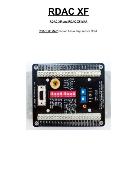
<strong>RDAC</strong> <strong>XF</strong><br />
<strong>RDAC</strong> <strong>XF</strong> and <strong>RDAC</strong> <strong>XF</strong> MAP<br />
<strong>RDAC</strong> <strong>XF</strong> MAP version has a map sensor fitted.
Input Connections<br />
TC 1 to 12<br />
GND<br />
OIL P<br />
OIL T<br />
FUEL P<br />
COOL<br />
CURR<br />
Inputs for use with thermocouple temperature probes. Typcally<br />
used for EGT probes (K-types) and CHT probes (K or J types).<br />
Can also be used for other types of temperature monitoring<br />
depending on abilities of connected system.<br />
Grounding point. Connected to the engine block, also used as<br />
ground for sensors not electrically connected to the engine itself<br />
such as flow senders and current senders.<br />
Oil pressure sender<br />
Oil temperature sender<br />
Fuel pressure sender<br />
Coolant temperature sender<br />
Electrical current sender (Example: <strong>MGL</strong> magnetic current<br />
sender)<br />
FL 1 Fuel level sender for tank 1<br />
FL 2 Fuel level sender for tank 2<br />
AUX 1 & AUX 2<br />
RPM 1 Engine RPM input 1<br />
RPM 2<br />
5V OUT<br />
FF 1 Fuel flow sender 1<br />
FF 2<br />
MAP Sensor<br />
Auxiliary inputs. Used for example for Rotax 912/914 NTC type<br />
CHT probes<br />
Engine RPM input 2 (also used for Rotor RPM for some systems)<br />
5V DC supply output. Intended only for low current users (30mA<br />
maximum). Typically used as supply point for <strong>MGL</strong> fuel flow<br />
senders.<br />
Fuel flow sender 2 (also used for tank return flow sender in a<br />
differential flow installation)<br />
This 1/8” NPT fitting connects to an internal MAP pressure sensor<br />
(Range: 0.2 – 2.5 Bar). Optional, fitted to <strong>RDAC</strong> <strong>XF</strong> MAP
DB9 Connections<br />
pin 1 OPT- Used only with EFIS systems fitted with a three way <strong>RDAC</strong><br />
connector.<br />
Connect to “- or Ground” of <strong>RDAC</strong> connector.<br />
pin 2 TX RS232 TX line. Used for OEM applications only.<br />
pin 3 RX RS232 RX line. Used for OEM Applications only.<br />
pin 4 OPT+ Used only with EFIS systems fitted with a three way <strong>RDAC</strong><br />
connector.<br />
Connect to center connector (signal) of <strong>RDAC</strong> connector.<br />
pin 5 GND Ground. Connect this to engine block (and engine block to battery<br />
negative). Do not connect directly to battery negative. This must be<br />
routed via the engine block.<br />
pin 6 CAN+ CANH signal line to EFIS<br />
pin 7 CAN- CANL signal line to EFIS<br />
pin 8 VIN +12V supply from battery via power switch / circuit breaker and fuse<br />
if required.<br />
pin 9 GND Ground. Connect this to engine block (and engine block to battery<br />
negative). Do not connect directly to battery negative. This must be<br />
routed via the engine block.<br />
This terminal may be left unconnected if desired, it is connected to<br />
pin 5 internally.<br />
DIP Switches<br />
<strong>RDAC</strong> SEL B & <strong>RDAC</strong> SEL A<br />
These switches are used to assign each<br />
<strong>RDAC</strong> in the system with an ID number.<br />
up to four <strong>RDAC</strong>s can be connected at the<br />
same time on the CAN interface.<br />
Note: set both switches to “off” for a single<br />
<strong>RDAC</strong> installation.<br />
AUX 1 PU used to pull the AUX 1 sensing line high<br />
AUX 2 PU used to pull the AUX 2 sensing line high<br />
OIPP PD used to pull the OILP line low<br />
OIPP PU used to pull the OILP line high<br />
Fuel P PU used to pull the Fuel Pressure sensing line<br />
high<br />
Coolant PU used to pull the Coolant sensing line high<br />
Fuel level 2 PU<br />
Fuel level 1 PU<br />
RPM 2 Filter<br />
used to pull the Fuel level 2 sensing line<br />
high<br />
used to pull the Fuel level 1 sensing line<br />
high<br />
Adds a high frequency filter to the signal
RPM 2 Ballast<br />
RPM 2 High Gain<br />
RPM 1 Filter<br />
RPM 1 Ballast<br />
RPM 1 High Gain<br />
PD = pull down resister<br />
This drawing illustrates the pull up resister circuit<br />
path<br />
used when the RPM 2 signal line requires a<br />
220 ohm ballast resister to ground<br />
used when the RPM 2 signal needs a High<br />
Gain (increases signal sensitivity<br />
approximately by a factor 10)<br />
Adds a high frequency filter to the signal<br />
path<br />
used when the RPM 1 signal line requires a<br />
220 ohm ballast resister to ground<br />
used when the RPM 1 signal needs a High<br />
Gain (increases signal sensitivity<br />
approximately by a factor 10)<br />
PU = pull up resister<br />
This drawing illustrates the pull up and pull down resister<br />
circuit for the oil pressure<br />
These circuits shows how the various PU switches feeds 5 volt onto the input(sense) line if<br />
required. Please check the senders information for type and settings needed.<br />
The 2 nd circuit shows a pull down circuit that has a 100Ω load resister switched to GND.<br />
This intended for use with the Rotax 4-20 mA oil pressure sender. The white wire is<br />
connected to the OILP input on the <strong>RDAC</strong> <strong>XF</strong>. The OILP PD switch must be in the ON<br />
position and the OIL PU switch must be in the OFF position.<br />
Passive senders such as resistive temperature and pressure senders will require the pullup<br />
resistor to be “ON”. If you are using active senders (mostly used as electronic pressure<br />
senders) please switch the pull-up resistor “OFF”.<br />
Default settings for most installations (assuming the Rotax 4-20mA sender is not used):
Sensitivity gain adjust<br />
RPM 1 MIN MAX<br />
RPM 2 MIN MAX<br />
Adjusts sensitivity of the RPM1 input<br />
Adjusts sensitivity of the RPM2 input<br />
Sensitivity to input signals on the RPM inputs can be adjusted over a wide range I two<br />
switchable ranges (via the DIPSwitch selection, high and low range).<br />
Highest sensitivity achievable is around 0.4V peak to peak in high gain and 4V peak to<br />
peak in low gain. From this level, the trimmers can be used to reduce the gain over a very<br />
wide range to around 50V peak to peak or higher depending on trimmer setting.<br />
Indicator<br />
The green LED flashes at about 1Hz during operation. If the LED is steady “ON” there is a<br />
serious fault with the <strong>RDAC</strong> and it cannot operate. If the LED is “OFF” the <strong>RDAC</strong> is not<br />
being supplied with power or there is a serious fault with the <strong>RDAC</strong>.<br />
INSTALLATION<br />
Precautions<br />
Note that the unit is not waterproof, when installing the unit in a location where it will be<br />
exposed to fluids it is advisable to install it in an enclosure(box)<br />
This unit is intended for mounting on the aircraft's fire-wall,engine side.<br />
The unit is not designed for mounting directly to the engine!<br />
Excessive vibration , moisture and temperature extremes will damage the <strong>RDAC</strong> or<br />
shorten its life span.<br />
Advisory !<br />
Once installation is complete and all setups regarding <strong>RDAC</strong> <strong>XF</strong> are done, it is important<br />
for the dip switches and sensitivity gain adjustment to be covered (Suggestion: clear self<br />
adhesive film)<br />
This is to prevent dust and moisture getting in to the switches, variable resisters and other<br />
components.
<strong>RDAC</strong> <strong>XF</strong> DIMENSIONS<br />
WIRING<br />
It is important to connect the <strong>RDAC</strong> ground wire to the engine block. Failure to do so will<br />
result in the readings from the engine sensors to be incorrect. Please note that the<br />
following steps need to be done correctly otherwise unit may function incorrectly or<br />
damage could result from bad installation. Take care to insulate all exposed connections.<br />
Plan your wire routings carefully to minimise chaffing of cables. The engine compartment<br />
may get hot so use suitable wire.<br />
Make neat connections with minimal exposed wire showing from connectors. If you are not<br />
sure, then ask for advise from an AMO.<br />
Connecting to EFIS / I-EFIS<br />
Connecting the <strong>RDAC</strong> to an EFIS / IEFIS can be done in one of three ways.<br />
The ENIGMA, VOYAGER and ODYSSEY G1 EFIS units can only use the OPT<br />
connection.<br />
OPT (optical) is the the connection that is used on the EFIS units and connects to the<br />
<strong>RDAC</strong>1 input on the back of the units.<br />
The ODYSSEY G2(pending relevant software updates) and the IEFIS systems use only<br />
the CAN interface.<br />
XTreme EFIS, XTreme EMS can use one <strong>RDAC</strong> <strong>XF</strong> connected via CAN interface.
Connection to an ENIGMA, VOYAGER or ODYSSEY G1 and G2<br />
The <strong>RDAC</strong> <strong>XF</strong> has a RS232 connection .<br />
This connection is only used for OEM and 3 rd party<br />
applications and is not used with any of <strong>MGL</strong> systems!<br />
Connections to an ODYSSEY G2 and I-EFIS units<br />
When using CAN interface, you can connect up to four <strong>RDAC</strong> <strong>XF</strong> s together.<br />
Observe the polarity of the two CAN wires. One of the lines is called “CAN-” or “CANL”, the<br />
other “CAN+' or “CANH” depending on equipment. It is recommended that a twisted pair<br />
wire is used for this connection using two wire colors for ease of identification. The CAN<br />
bus must be terminated at each end with a 120 ohm resistor. Connections from equipment<br />
into the CAN bus (other than the ends) must only use short stubs into the bus (maximum<br />
length of a stub should not exceed 20cm if possible).<br />
It is OK to use only a single resistor of value 60-120 ohms if the total length of the CAN<br />
bus is not more than two meters (6 feet).<br />
You will need to set the <strong>RDAC</strong> SEL switches to the correct order so the ODYSSEY G2<br />
and IEFIS depending on the number of <strong>RDAC</strong> units you have on your bus. Normally, only<br />
a single unit is used and thus the two SEL switches are set to “off”.<br />
Table for Rdac number<br />
The CAN bus will typically be shared with other equipment such as AHRS, compass,<br />
transponders etc. Please ensure that the CAN bus wiring is done to high standards and all<br />
connections are secure as this is a critical link in your aircraft.
Thermocouple Probes Inputs (egt/cht)<br />
TC 1 to 12 provide up to 12 channels for thermocouple temperature sensors. You can use<br />
“K” TYPE thermocouple probes for EGT and “K or J” TYPE thermocouple probes as CHT<br />
sensors. Note that you need to setup the EFIS so it knows the probe types and what<br />
channels you are using.<br />
.<br />
The TC setups on Enigma, Voyager, Odyssey G1 and G2 units<br />
are programmed to see the first TC inputs as EGTs then<br />
followed immediately by CHTs. Example: 2 EGTs and 4 CHTs<br />
then TC1=EGT1, TC2=EGT2, TC3=CHT1, TC4= CHT2,<br />
TC5=CHT3 and TC6=CHT4.<br />
On IEFIS systems you can assign TC channels as you prefer. It is however recommended<br />
to follow the above guide by grouping your EGT probes starting at TC1, followed by a<br />
group of CHT probes.<br />
Depending on how many probes used for the engine ,it is possible to use open TC inputs<br />
with probes for monitoring other components like bearings, pulleys or gearboxes ect. Note<br />
that you need to use the screen design program to add these extra items into your desired<br />
screen pages on the IEFIS or EFIS systems<br />
Note that thermocouple sensors can not be sheared across two <strong>RDAC</strong>s.<br />
These are some examples of “J” and “K” type thermocouple lead colour codes<br />
and corresponding polarity
RDAX <strong>XF</strong> thermocouple guidelines<br />
The thermocouple amplifier is a precision device providing full cold junction<br />
compensation and bow voltage correction. In addition the amplifier measures<br />
and corrects for its own errors. This results in very accurate measurements<br />
providing you install high quality probes. Here are some guidelines:<br />
EGT Probes: select probes that are made from 316 stainless steel and that<br />
use glass-fiber insulated conductors. Teflon insulated conductors as found in<br />
many cheap probes introduce errors as the insulation melts moving the<br />
measuring point towards the mounting bolt which transfers a lot of heat to the<br />
exhaust material. This results in under reading probes. Stay away from<br />
probes that use simple plastic heat shrink sleeving – it does not last. Choose<br />
probes that use a generous amount of stainless steel spring as strain relief.<br />
The Bolt itself should be stainless as well or it will rust very quickly.<br />
CHT probes: These are made from washers to fit spark-plug bases.<br />
Temperatures are considerably lower so most thermocouple cables will work<br />
without problems. The biggest area of concern should be the connection of<br />
the thermocouple cable to the washer. This often breaks after the spark plug<br />
has been changed a few times. Choose a probe that is suitably reinforced at<br />
this point for a long and trouble free life.<br />
EGT and CHT probes supplied by <strong>MGL</strong> <strong>Avionics</strong> are of highest quality. We<br />
recommend that you consider using our probes if at all possible.<br />
Warning: Four stroke engines produce much hotter exhaust gases compared<br />
to two stroke engines. Do not use EGT probes made from lower grade<br />
stainless steel (for example 310), these probes will not withstand the high<br />
temperatures and can fail as the metal gets very soft at 800 degrees C. Many<br />
four strokes (such as the Rotax 912) will produce exhaust gases of up to 850<br />
degrees C.<br />
Important installation note:<br />
EGT and CHT probes use wire made from plain Iron and other basic metals.<br />
As a result these probes are not able to withstand much flexing of the wires<br />
due to engine vibrations. Avoid making nice looking coils or similar<br />
constructions that will result in excessive vibration or flexing of the wire. Route<br />
the cables from the probe points tightly along suitable engine mounting points<br />
eliminating any chance of unnecessary wire flexing during engine operation.
Oil, Fuel Pressure and Coolant monitoring<br />
Oil P<br />
OIL T<br />
FUEL P<br />
COOL<br />
connect to oil pressure sender<br />
connect to oil temperature sender<br />
connect to fuel pressure sender<br />
connect to water temperature sender<br />
It is important to know what type, range and connections are needed for the sensors.<br />
In the EFIS and I-EFIS units menu's relating to the sensors placement can show you what<br />
sensor types can be used.<br />
Most sensor types are resistive. In this case you have a pull-up resistor enabled via the<br />
DIPSWITCH array. The pull-up resistor connects to 5V DC internally. The sensors<br />
resistance forms a resistive voltage divider to ground. The resultant voltage on the sensor<br />
is measured and translated into a sensor reading depending on the type of sensor<br />
connected.<br />
Electronic pressure senders tend to output a voltage level in proportion to applied<br />
pressure. For these devices it is recommended to switch the pull-up resistor off.<br />
Rotax 4-20 mA oil pressure sender part no.956413. The sensor cable is approx. 3 m long<br />
and has 3 leads. The Black lead is not to be connected and has no function. The Red lead<br />
from the sensor has to be connected to the positive bus via a fuse or circuit breaker The<br />
White lead (output signal) has to be connected directly to the<br />
OILP input on the <strong>RDAC</strong> <strong>XF</strong>. The OILP PD switch must be in the on position<br />
and the OILP PU switch must be in the off position.<br />
This sets up the <strong>RDAC</strong> <strong>XF</strong> to measure the current<br />
injected into the grounded 100 ohm resistor.
Current Input<br />
CURR<br />
connect to <strong>MGL</strong> Current Sensor or any other electronic current sensor<br />
that provides an output centered around 2.5V for zero current.<br />
This example shows connection of the <strong>MGL</strong> Magnetic current sensor.<br />
Connect sensor wires as indicated.<br />
Connect the current sensor power (red wire) to the<br />
<strong>RDAC</strong> positive supply and the black wire to GND<br />
The magnetic current sensor can be installed in several ways depending on the current<br />
range it is to measure. Please refer to the documentation for this sensor.
Fuel Level Inputs<br />
FL 1<br />
FL 2<br />
connects to fuel level sender output/signal from tank1<br />
connects to fuel level sender output/signal from tank 2 ( if installed)<br />
Safety Hazard ! Please read this:<br />
Be careful when installing fuel level senders into fuel tanks. Ensure that the<br />
fuel tank is completely empty when you proceed with the installation. Ensure<br />
that the fuel tank is well ventilated and does not contain any fuel vapors –<br />
these are highly explosive when mixed with air.<br />
Ensure that at all times the ground connection (the connection of the fuel level<br />
sender mounting flange) is securely connected to the aircraft frame (in case of<br />
a metal frame) and to the negative terminal of the battery. In addition the<br />
negative terminal of the battery must at all times be connected to the Supply<br />
ground terminal of the <strong>RDAC</strong> X EMS.<br />
Please note – this wiring is critical and must never break in flight. It would be<br />
possible to create electrical sparks in the fuel tank if your wiring is faulty or<br />
incorrect. The consequences of this can be imagined. This has nothing to do<br />
with the <strong>RDAC</strong> EMS itself but is a general hazard for any automotive fuel level<br />
sender installation.<br />
If you have no experience with electrical wiring, PLEASE delegate the task to<br />
a qualified automobile electrician or electronics technician.<br />
If you need to remove the <strong>RDAC</strong> X EMS, please first disconnect and secure<br />
the fuel level sender wire before disconnecting anything else.
Aux Inputs<br />
AUX 1<br />
AUX 2<br />
is an axillary input for extra temperature sensors( cht1,coolant)<br />
is an axillary input for extra temperature sensors (cht2)<br />
The AUX inputs can be used to measure<br />
temperature or pressure with the use of a variable resistance<br />
NTC type probes.<br />
Electronic sensors such as the popular type LM335 can<br />
also be used.<br />
This is a typical Rotax 912/914 CHT<br />
sensor connection. With this setup the<br />
AUX 1 PU and AUX 2 PU switches<br />
will be in the ON position.
Rpm Inputs<br />
RPM 1<br />
units<br />
RPM 2<br />
This input connects to one of your magneto, ignition, ecu or pick-up<br />
This input can be used to see your second mag rpm<br />
( dual magneto, ecu or ignition units)<br />
This input is also setup for EXTREME units to get a rotor rpm feed.<br />
( auto gyro or helicopters) This setup is only for the Xtreme EFIS!<br />
On the EFIS AND IEFIS units the RPM generally works by taking the highest RPM reading<br />
for display on the standard screens.<br />
This drawing of a system that uses a pick-up sensor (Hall Effect Sensor) sometimes seen<br />
on Rotax engines<br />
Each RPM input has the following options:<br />
Noise filter: This can be switched into the signal path to help in removing high frequency<br />
noise artefacts from the signal that can result in unstable readings. Use this switch only if<br />
you rely on a “dirty” signal. An example of such a signal is a direct coupling to a magneto<br />
device.<br />
Ballast resistor: This switches a 220 ohm ballast resistor to ground. This can be used to<br />
reduce noise or secondary pulses on the RPM line. Often used with Rotax engines. Note:<br />
For direct magneto pickups this switch must be “OFF” as otherwise the magneto pulse<br />
may have low energy in particular at idle.<br />
Gain setting: Switch “on” selects a high gain. In this case the input is about 10 times more<br />
sensitive than normal. Used only for low level signals such as inductive pickup coils.
Typical sensitivity settings and resultant minimum signal levels:<br />
RPM 1 shows ¼ turn RPM 1 shows mid position RPM 1 shows max position<br />
RPM 1 High Gain on 3.5 volt (peak to peak) 0.8 volt (peak to peak) RPM 1 High Gain on RPM 1 High Gain ON 0.4 volt (peak to peak)<br />
RPM High Gain OFF 35 volt (peak to peak) RPM High Gain OFF 8 volt (peak to peak) RPM High Gain OFF 4 volt (peak to peak)<br />
RPM 1 High Gain<br />
turned ON<br />
RPM 1 High Gain<br />
turned OFF<br />
ECU units may have a digital<br />
RPM output you may be able<br />
to use<br />
This a drawing of a magneto system. In this case<br />
the RPM feeds are taken from the “P” connection<br />
terminal.<br />
Note that the two magnetos are connected to<br />
the appropriate RPM inputs with a<br />
recommended 10KΩ (10.000 ohms)<br />
resister in line. In this case you would<br />
have the RPM 1&2 BALLAST switches in<br />
the OFF position.
Fuel Flow Inputs<br />
This example is based on typical <strong>MGL</strong> flow senders:<br />
FF1 & FF2 Connection of fuel flow sender ( Braid to GND, Red to +5 volts, Blue to FF1)<br />
If a second fuel flow sensor is used then the braid and red wires of the second<br />
flow sender connect as the first sender but the blue wire (signal) connects to<br />
FF2.<br />
Using the Fuel Flow Sender<br />
Note the setup for Fuel flow sender<br />
on EFIS unit ”Fuel related setup;<br />
Fuel flow setup menu”<br />
“Flow sender type Rdac one: Turbine<br />
It is important to install the<br />
fuel flow sender at an angle so that<br />
will no bubbles can get trapped in the<br />
impeller section. This will cause<br />
incorrect or erratic readings.<br />
It is also important to work out what fuel flow<br />
to expect (generally manufacturers specify fuel usage per hour)<br />
in order to select the right jet for the fuel flow sender unit.<br />
Please note that the installation of the Fuel Flow sender should be done in<br />
such a fashion that dirt or debris from the fuel tank cannot lodge inside the<br />
flow sender. These will not block your fuel flow but may lead to the impeller<br />
inside the sender jamming. It is usually sufficient to mount the Flow sender<br />
AFTER the fuel filter but before the fuel pump. It is a good idea to provide a<br />
small reservoir such as a primer bulb between the flow sender and the fuel<br />
pump.<br />
Using Injectors<br />
In this injector system is the injector<br />
has a +12volts connection but the<br />
negative (low) side of the injector is<br />
switched/fired by the electronic<br />
injector control system.<br />
For this reason in ”Fuel related<br />
setup;<br />
Fuel flow setup menu” the selection<br />
should show as “Flow sender type<br />
Rdac one: InjectorL”<br />
Most systems used are low<br />
triggering/firing systems<br />
If a positive(high) switching/ firing<br />
injector system is used then the<br />
selection will show<br />
“Flow sender type Rdac one: InjectorH”
Manifold Air Pressure Input<br />
Please note that the MAP Sensor is only available on th <strong>RDAC</strong> <strong>XF</strong> MAP<br />
The MAP Sensor is connected to the manifold.<br />
This sensor measures the air pressure or vacuum in the manifold.<br />
In the case of the 912 and 914 Rotax engines there is a pipe connecting<br />
the two manifolds where this connection can be made.<br />
On the <strong>RDAC</strong> there is a standard 1/8 th NPT female threaded fitting.
Temperature monitoring connection for Rotax 582<br />
A typical sensor connection layout
Technical data<br />
Weight <strong>RDAC</strong> <strong>XF</strong><br />
Weight <strong>RDAC</strong> <strong>XF</strong> MAP<br />
Power supply:<br />
CAN bus:<br />
RS232:<br />
OPT:<br />
Temperature range:<br />
340 grams<br />
370 grams<br />
9-18V DC. DO-160 compliant to 120V/10mS pulse<br />
250kBaud, 11bit identifiers, <strong>MGL</strong> CAN bus protocol<br />
38400 Baud<br />
1250 Baud<br />
-30 degrees C to +70 degrees C ambient (operation)<br />
Thermocouple common mode range: -2V to +3V with respect to GND terminals<br />
Thermocouple temperature range: up to 1200 degrees C (K-type probes)<br />
Analog input pull up resistors to +5V:<br />
AUX1, AUX2, OILT, COOL: 1500 ohms<br />
OILP: 1000 ohms<br />
FL1, FL2: 220 ohms<br />
RPM inputs:<br />
Input impedance (A/C coupled):<br />
High gain: 15.000 ohms<br />
Low gain: 110.000 ohms<br />
Ballast resistor (switchable): 220ohms, 5W to GND, DC coupled


