The JT4 Coding Process (Plain Text messages only) - G4JNT
The JT4 Coding Process (Plain Text messages only) - G4JNT
The JT4 Coding Process (Plain Text messages only) - G4JNT

You also want an ePaper? Increase the reach of your titles
YUMPU automatically turns print PDFs into web optimized ePapers that Google loves.
<strong>The</strong> <strong>JT4</strong> <strong>Coding</strong> <strong>Process</strong> (<strong>Plain</strong> <strong>Text</strong> <strong>messages</strong> <strong>only</strong>)<br />
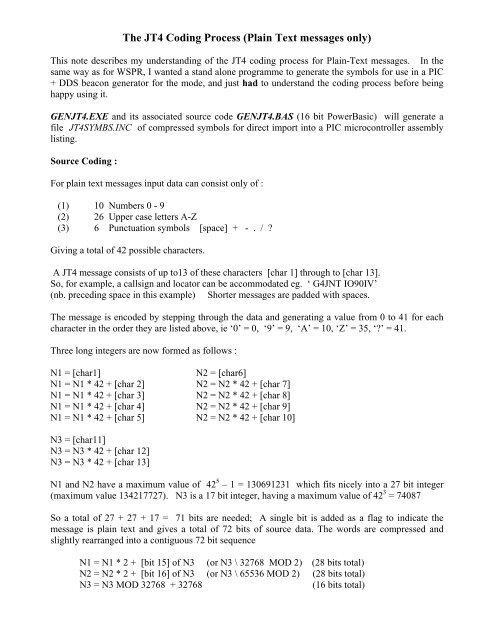
This note describes my understanding of the <strong>JT4</strong> coding process for <strong>Plain</strong>-<strong>Text</strong> <strong>messages</strong>. In the<br />
same way as for WSPR, I wanted a stand alone programme to generate the symbols for use in a PIC<br />
+ DDS beacon generator for the mode, and just had to understand the coding process before being<br />
happy using it.<br />
GEN<strong>JT4</strong>.EXE and its associated source code GEN<strong>JT4</strong>.BAS (16 bit PowerBasic) will generate a<br />
file <strong>JT4</strong>SYMBS.INC of compressed symbols for direct import into a PIC microcontroller assembly<br />
listing.<br />
Source <strong>Coding</strong> :<br />
For plain text <strong>messages</strong> input data can consist <strong>only</strong> of :<br />
(1) 10 Numbers 0 - 9<br />
(2) 26 Upper case letters A-Z<br />
(3) 6 Punctuation symbols [space] + - . / ?<br />
Giving a total of 42 possible characters.<br />
A <strong>JT4</strong> message consists of up to13 of these characters [char 1] through to [char 13].<br />
So, for example, a callsign and locator can be accommodated eg. ‘ <strong>G4JNT</strong> IO90IV’<br />
(nb. preceding space in this example) Shorter <strong>messages</strong> are padded with spaces.<br />
<strong>The</strong> message is encoded by stepping through the data and generating a value from 0 to 41 for each<br />
character in the order they are listed above, ie ‘0’ = 0, ‘9’ = 9, ‘A’ = 10, ‘Z’ = 35, ‘?’ = 41.<br />
Three long integers are now formed as follows :<br />
N1 = [char1]<br />
N2 = [char6]<br />
N1 = N1 * 42 + [char 2] N2 = N2 * 42 + [char 7]<br />
N1 = N1 * 42 + [char 3] N2 = N2 * 42 + [char 8]<br />
N1 = N1 * 42 + [char 4] N2 = N2 * 42 + [char 9]<br />
N1 = N1 * 42 + [char 5] N2 = N2 * 42 + [char 10]<br />
N3 = [char11]<br />
N3 = N3 * 42 + [char 12]<br />
N3 = N3 * 42 + [char 13]<br />
N1 and N2 have a maximum value of 42 5 – 1 = 130691231 which fits nicely into a 27 bit integer<br />
(maximum value 134217727). N3 is a 17 bit integer, having a maximum value of 42 3 = 74087<br />
So a total of 27 + 27 + 17 = 71 bits are needed; A single bit is added as a flag to indicate the<br />
message is plain text and gives a total of 72 bits of source data. <strong>The</strong> words are compressed and<br />
slightly rearranged into a contiguous 72 bit sequence<br />
N1 = N1 * 2 + [bit 15] of N3 (or N3 \ 32768 MOD 2) (28 bits total)<br />
N2 = N2 * 2 + [bit 16] of N3 (or N3 \ 65536 MOD 2) (28 bits total)<br />
N3 = N3 MOD 32768 + 32768<br />
(16 bits total)
Adding 32768 or setting bit 15 of N3 is the plain text flag<br />
<strong>The</strong> contiguous 72 bit sequence is made up of N1 * 2 (16 + 28) + N2 * 2 16 + N3<br />
In GEN<strong>JT4</strong>.BAS the data is represented in a string format from this point on.<br />
31 zero bits are added at the end to make a 103 bit sequence for the next stage.<br />
Convolutional Encoding<br />
<strong>The</strong> data is now expanded to add FEC with a rate ½, constraint length 32, convolutional encoder.<br />
<strong>The</strong> 103 bits (including trailing zeros) are read out MSB first:<br />
(using the string representation, one-at-a-time from the left hand end)<br />
<strong>The</strong> bits are clocked simultaneously into the right hand side, or least significant position, of two 32<br />
bit shift registers [Reg 0] and [Reg 1]. Each shift register feeds an Exclusive-OR parity generator<br />
from feedback taps described respectively by the 32 bit values 0xF2D05351 and 0xE4613C47.<br />
Parity generation starts immediately the first bit appears in the registers (which must be initially<br />
cleared) and continues until the registers are flushed by the final 31 st zero being clocked into them.<br />
Each of the 103 bits shifted in generates a parity bit from each of the generators , a total of 206 bits<br />
in all. For each bit shifted in, the resulting two parity bits are taken in turn, in the order the two<br />
feedback tap positions values are given, to give a stream of 206 output bits.<br />
<strong>The</strong> parity generation process is :<br />
Shift the next source bit into the LSB of both [Reg 0] and [Reg 1],<br />
moving the existing data in each one place left<br />
Take the contents of [Reg 0]<br />
AND with 0xF2D05351<br />
Calculate the single bit parity (XOR) of the resulting sum.<br />
Append to the output data stream<br />
Take the contents of [Reg 1]<br />
AND with 0xE4613C47<br />
Calculate the single bit parity (XOR) of the resulting sum.<br />
Append to the output data stream<br />
<strong>The</strong> expansion from 72 source data bits to 206 has added sufficient redundancy in an optimised<br />
manner to give a code capable of very strong Forward Error Correction against random errors.<br />
Interleaving<br />
Errors over a radio link are rarely random , being more likely to occur in bursts against which this<br />
sort of convolutional coding is less effective,. So the final stage of encoding is to mix up, or<br />
interleave. the 206 data bits so as to move adjacent bits away from each other in time. <strong>The</strong> result is<br />
that close-together bits corrupted by burst interference are spread throughout the frame and therefore<br />
appear as random errors – which the FEC process can cope with.
<strong>The</strong> interleaving process is performed by taking the block of 206 starting bits labelled S[0] to<br />
S[205] and using a bit reversal of the address to reorder them, to give a pattern of destination bits<br />
referred to as D[0] to D[205].<br />
Initialise a counter, P to zero<br />
Take each 8-bit address from 0 to 255, referred to here as I<br />
Bit-reverse I to give a value J.<br />
For example, I = 1 gives J = 128, I = 13 J = 176 etc.<br />
If the resulting bit-reversed J yields a value less than 206 then :<br />
Set Destination bit D[J] = source bit S[P]<br />
Increment P<br />
Stop when P = 206<br />
This completely shuffles and reorders the 206 bits on a one-to-one basis.<br />
A single zero bit is now appended to the start of the start of the interleaved sequence. This serves as<br />
a reference tone if phase encoding is adopted (JT2 mode)<br />
Merge With Sync Vector<br />
<strong>The</strong> 207 bits of data are now merged with 207 bits of a pseudo random synchronisation word having<br />
good auto-correlation properties. Each source bit is combined with a sync bit taken in turn from the<br />
table below to give a four-state symbol value:<br />
Symbol[n] = Sync[n] + 2 * Data[n]<br />
207 bit Synchronisation Vector<br />
0,0,0,0,1,1,0,0,0,1,1,0,1,1,0,0,1,0,1,0,0,0,0,0,0,0,1,1,0,0,0,0,0,0,0,0,0,0,0,0<br />
1,0,1,1,0,1,1,0,1,0,1,1,1,1,1,0,1,0,0,0,1,0,0,1,0,0,1,1,1,1,1,0,0,0,1,0,1,0,0,0<br />
1,1,1,1,0,1,1,0,0,1,0,0,0,1,1,0,1,0,1,0,1,0,1,0,1,1,1,1,1,0,1,0,1,0,1,1,0,1,0,1<br />
0,1,1,1,0,0,1,0,1,1,0,1,1,1,1,0,0,0,0,1,1,0,1,1,0,0,0,1,1,1,0,1,1,1,0,1,1,1,0,0<br />
1,0,0,0,1,1,0,1,1,0,0,1,0,0,0,1,1,1,1,1,1,0,0,1,1,0,0,0,0,1,1,0,0,0,1,0,1,1,0,1<br />
1,1,1,0,1,0,1<br />
Resulting in 207 sequential symbols each with a value from 0 to 3
Modulation<br />
Each symbol represents a frequency shift of 11025 / 2520, or 4.375Hz, per Symbol Value, multiplied<br />
by a constant K depending on the <strong>JT4</strong>a to <strong>JT4</strong>g mode and leading to a four-level Multi-FSK<br />
modulation. <strong>The</strong> transmitted symbol length is the reciprocal of the tone spacing, or approximately<br />
0.229, so the complete message of 207 symbols takes around 47 seconds to send and occupies a<br />
bandwidth of approximately (3.K.+ 1)* 4.375 Hz (three spacing intervals plus the keying<br />
bandwidth).<br />
Tone spacing<br />
multipliers<br />
<strong>JT4</strong>a K = 1<br />
<strong>JT4</strong>b K = 2<br />
<strong>JT4</strong>c K = 4<br />
<strong>JT4</strong>d K = 9<br />
<strong>JT4</strong>e K = 18<br />
<strong>JT4</strong>f K = 36<br />
<strong>JT4</strong>g K = 72<br />
Conventionally, and presumably for compatibility with other WSJT modes,<br />
the centre frequency of the transmission is defined as 11025Hz / 1024 * 118<br />
= 1270.46Hz which lies at tone position 1.5 (midway between tones 1 and<br />
2) So the audio frequency corresponding to Tone Zero is now :<br />
11025/1024 * 118 – 1.5 * 4.375 * K<br />
As a sanity-check, for <strong>JT4</strong>g, with K = 72 Tone zero lies at 797.959Hz (800<br />
Hz is near enough!) and the tone spacing is 315Hz for a total signal<br />
bandwidth a few Hz over 945Hz<br />
Packing for export and storage<br />
For export, the 207 two-bit symbols are packed four to a byte, MSB first, into 52 locations with<br />
appropriate formatting for PIC assembly code.<br />
; <strong>JT4</strong> Symbols generated from GEN<strong>JT4</strong> <strong>G4JNT</strong> Jul 2009<br />
; Message data ' <strong>G4JNT</strong> IO90IV'<br />
de 0x20 0xDA 0x3E 0x50 0xCC 0xAA 0x2D 0x20<br />
de 0x00 0x82 0x65 0x34 0xC5 0xD4 0x4A 0xE1<br />
de 0x25 0xF4 0x06 0xC0 0x75 0x96 0x18 0x14<br />
de 0x6C 0xEE 0x55 0xC4 0xC7 0xBB 0x37 0x86<br />
de 0xF3 0xF4 0xA3 0x45 0x29 0xD9 0xD9 0xF2<br />
de 0x40 0xF1 0x63 0x03 0x5F 0xCB 0x48 0x16<br />
de 0x8C 0x71 0x54 0xCC<br />
Andy Talbot <strong>G4JNT</strong> July 2009