

FF-2 - MGL Avionics
FF-2 - MGL Avionics
FF-2 - MGL Avionics

Create successful ePaper yourself
Turn your PDF publications into a flip-book with our unique Google optimized e-Paper software.
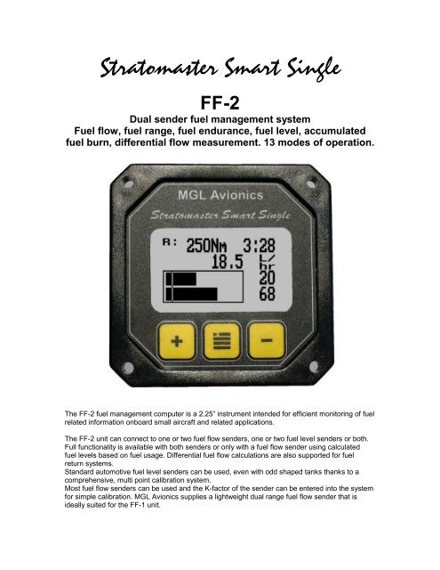
Stratomaster Smart Single<br />
<strong>FF</strong>-2<br />
Dual sender fuel management system<br />
Fuel flow, fuel range, fuel endurance, fuel level, accumulated<br />
fuel burn, differential flow measurement. 13 modes of operation.<br />
The <strong>FF</strong>-2 fuel management computer is a 2.25” instrument intended for efficient monitoring of fuel<br />
related information onboard small aircraft and related applications.<br />
The <strong>FF</strong>-2 unit can connect to one or two fuel flow senders, one or two fuel level senders or both.<br />
Full functionality is available with both senders or only with a fuel flow sender using calculated<br />
fuel levels based on fuel usage. Differential fuel flow calculations are also supported for fuel<br />
return systems.<br />
Standard automotive fuel level senders can be used, even with odd shaped tanks thanks to a<br />
comprehensive, multi point calibration system.<br />
Most fuel flow senders can be used and the K-factor of the sender can be entered into the system<br />
for simple calibration. <strong>MGL</strong> <strong>Avionics</strong> supplies a lightweight dual range fuel flow sender that is<br />
ideally suited for the <strong>FF</strong>-1 unit.
The main display<br />
Fuel range<br />
Fuel endurance<br />
hours:minutes<br />
Fuel low<br />
alarm level<br />
Fuel flow<br />
Fuel level<br />
Remaining<br />
fuel<br />
Mode F+CT (Single Fuel flow, single Tank, calculated level)<br />
Mode F+PT (Single Fuel flow, single Tank, level sender)<br />
Mode DF+CT (Differential Fuel flow, single Tank, calculated level)<br />
Mode DF+PT (Differential Fuel flow, single Tank, level sender)<br />
Alternate main display for the above modes only – select between the two displays by using the<br />
“+” screen whenever you are not in the menu<br />
Mode <strong>FF</strong>+CTT (Dual fuel flow, dual Tank,<br />
calculated levels)<br />
Mode <strong>FF</strong>+PTT (Dual fuel flow, dual Tank, level<br />
senders)<br />
Mode F+PTT (Single fuel flow, dual Tank, level<br />
senders)<br />
Mode DF+PTT (Single fuel flow, dual Tank, level<br />
senders)
Mode F (Single Fuel flow)<br />
Mode <strong>FF</strong> (Dual Fuel flow)<br />
Mode PT (Single Tank, level sender)<br />
Mode PTT (Dual Tank, level senders)<br />
Mode DF (Differential Fuel flow)<br />
Note: This mode is used to show the flow of both<br />
forward flow and return flow senders. The<br />
calculation at the bottom of the screen shows how<br />
the fuel flow is derived.
Setting up the <strong>FF</strong>-2<br />
Press the Menu key to enter the menu. You can move forward and backwards in the menu by<br />
using the + and – keys. To change or select a menu item, move the highlight to the desired item<br />
and then press the Menu key. To end an edit or function, press the Menu key again.<br />
To exit the menu and continue normal operation, select the ***Done*** function and press the<br />
Menu key. Note, all changes you have initiated during your session will only be remembered by<br />
the instrument if you exit the menu using the ***Done*** function.<br />
The menu varies depending on the mode you have selected. The following pictures and<br />
descriptions show all the modes. Some items may not be visible if your selected mode does not<br />
require them.<br />
This shows all possible menu items<br />
Speed<br />
Enter your aircrafts cruising speed. This value will be used to calculate the fuel range, i.e. how far<br />
you can fly with remaining fuel at zero wind speed. For this calculation, your current remaining<br />
fuel, your current fuel flow and the speed entered here are taken into account.<br />
You can easily change the speed during flight to reflect changes in ground speed or cruising<br />
speed.<br />
Use this function with care and do not use it to extend your range. You must at all times have a<br />
secondary indication of available fuel. Note that flow senders and level senders may be subject to<br />
malfunction that may result in incorrect fuel levels being displayed or calculated.<br />
Level1, Level2<br />
This function is used to manually enter your current fuel level after fueling or defueling your<br />
aircraft. This function is only available if you do not have a mode selected where fuel level is<br />
calculated from fuel flow.<br />
Note that it is good airmanship to take into account a “silent” fuel reserve. For example, if you<br />
have a 50 liter tank and you fill it, enter 40 or 45 liters as your available fuel. Also view the text on<br />
“fuel tank size” below.<br />
Accu1, Accu2<br />
These entries show the amount of fuel used since the accumulator was last reset to zero. To<br />
reset the accumulator simply move the highlight over the accumulator and press the center menu<br />
key (Select key in menu mode).<br />
Contrast …<br />
This function allows you to change the display contrast to your liking. You can select values from<br />
about 20 to 45. (can vary depending on display type).<br />
BL …<br />
This function allows you to switch the display backlight on or off.<br />
Mode …<br />
Select the operating mode of your instrument, for example <strong>FF</strong>+CTT.<br />
Each “F” stands for a fuel flow sender.<br />
Each “T” stands for a fuel tank level display.<br />
“C” means “calculated fuel level”.<br />
“P” means “physical fuel level” (tank level sender).
Setup<br />
Select the “Setup” function to enter the setup menu for your selected mode. The pictures and<br />
descriptions here show all available functions. Depending on your mode selection some of these<br />
items may not be visible if they are not required.<br />
Now fly of a quantity of fuel, perhaps 25 liters as example (very roughly – it does not need to be<br />
exact). Note the reading of the fuel level after you switch off the engine. Assume we are reading<br />
28 liters now (we used 22 liters according to the instrument).<br />
Now fill the tank again, exactly to the previous level. Measure how much fuel you need to get to<br />
this previous level using a measuring jug.<br />
For example, assume we need 26 liters to get back to the previously marked fuel level. This<br />
means the the fuel level should have been at 24 liters as we started with a value of 40 liters.<br />
This example would mean that our fuel flow sender is under reading by four liters as it has not<br />
measured the correct quantity of fuel.<br />
Now start adjusting the K-Factor so your tank level changes from 28 liters to 24 liters. You would<br />
adjust the K-factor down in this case (fewer pulses per liter of fuel).<br />
Using this calibration method you can get to very accurate fuel flow readings. The initial accuracy<br />
of fuel flow readings is dependant on the viscosity or type of fuel you use, added oils, installation<br />
and finally the temperature of the fuel.<br />
A good installation can achieve about a +/- 3% accuracy with as little as 1% error after calibration.<br />
Alarm …<br />
Enter your desired minimum fuel value that you would like to trigger the fuel low alarm. The fuel<br />
low alarm will result in flashing of the fuel level display and remaining fuel readout. You can also<br />
connect a warning lamp to the external alarm output (see installation diagram).<br />
Note that the fuel low level will be displayed as a vertical line on your fuel level display. This level<br />
is over and above your “silent” fuel reserve.<br />
Each tank has its own alarm level.<br />
Units …<br />
Select your required units for distance and fuel quantity. The following options are available:<br />
L/M: Liters and statute miles<br />
G/M: U.S. Gallons and statute miles<br />
L/Nm: Liters and nautical miles<br />
G/Nm: U.S. Gallons and nautical miles<br />
L/Km: Liters and kilometers<br />
G/Km: U.S. Gallons and kilometers
Calibrate 1, Calibrate 2<br />
This function enters the fuel level sender calibration menu. The fuel level sender needs to be<br />
calibrated before it can be used with this system. The calibration allows the system to learn the<br />
shape of your tank as well as any errors your fuel level sender or installation has.<br />
The current level<br />
sender reading<br />
The six<br />
calibration<br />
points from<br />
zero fuel level<br />
to full tank<br />
Level sender<br />
readings at the<br />
calibration<br />
points<br />
Performing the calibration procedure. Note: You start with an empty tank, you need a measuring<br />
jug or fueling device that has calibration marks and you need enough fuel to fully fill the tank.<br />
Regardless of your use of a fuel flow sender, you can install a fuel level sender into your fuel<br />
tank. These level senders are inexpensive and are available as after market replacement fittings<br />
from a car spares outlet. We recommend the senders available from VDO. Be aware that some<br />
makes of cheap level senders can prove troublesome, as the lever arms tend to be sticky.<br />
This prevents the floats from floating on the surface of the fuel at all times. As a<br />
consequence, this will lead to incorrect fuel level indication.<br />
Once you have installed a fuel level sender into your tank, make sure the float can travel all the<br />
way from empty to full position without hindrance of any kind.<br />
The calibration procedure should be carried out with your aircraft in flight attitude. This means you<br />
need to lift the tail if you have a tail-dragger or lift the nose wheel if you have a weightshift trike.<br />
You start the calibration procedure with an empty tank.<br />
We now start with the empty tank. Add five liters of fuel (our reserve quantity) using a suitable<br />
measure. Make sure the measure is suitably accurate.<br />
This is now the “level sender reading at 0 Lt” position. Move the highlight to this position and wait<br />
until the sender reading has stabilized (You will see the sender reading at the top line). This could<br />
take up to a minute so have patience.<br />
ENSURE THAT THE FLOAT IS NOT SUBMERGED AND IS FLOATING ON TOP OF THE FUEL<br />
LEVEL.<br />
Should this number not react to changes of your level sender position, then you have a problem.<br />
Please check your wiring according to the installation section of this manual.<br />
You should expect the number to change in the region of at least 20 to 60 counts per calibration<br />
position. If the number does not change with fuel level or only changes a very small amount –<br />
check your installation. Something is not right !!!
If you see the number changing then everything is well. Once it has stabilized and the highlight is<br />
on the 0 Lt position, press the “Menu” key to transfer the reading from the sender to the<br />
calibration point.<br />
Now you are ready for the next step. Add the required amount of fuel to get to the next level (In<br />
our case 9 Lt – this is 20% tank capacity). Once done, wait for the reading to stabilize and press<br />
“Menu” again after you have moved the highlight to the “9 Lt” position.<br />
Proceed in a similar manner until you have reached the last calibration position at 100% tank<br />
capacity.<br />
You are done !<br />
If you press “+” past the last calibration point then the unit will display:<br />
If you press “Menu” at this point then the calibration function will exit<br />
and any changes you have done are written to permanent memory in<br />
the instrument. You can repeat this calibration many times so do not<br />
worry if you do not get it right the first time.<br />
The instrument uses the 6 calibration points to work out a correction curve that takes into account<br />
the tolerances of your fuel level sender and the shape of your fuel tank. This results in an<br />
incredibly accurate and usable fuel level display that far exceeds that available from ordinary dial<br />
type gauges.<br />
Note:<br />
The calibration positions may be edited by using the + and – keys. This allows you, in theory, to<br />
copy calibration settings from one instrument to another. We however recommend that you do go<br />
though the calibration procedure even if the two aircraft are identical in all respects. Tolerances<br />
do exist and the calibration cancels these out.<br />
Accurate fuel level displays are a vital safety factor for an aircraft and a very useful feature for<br />
peace of mind during cross county flights.<br />
Notes on Slope error<br />
Sender value is a value determined by the <strong>FF</strong>-2. It is used to calculate e.g. fuel level, fuel<br />
endurance estimate and current range estimate. The fuel tank setup sender value can either<br />
increase in value as fuel is added on decrease in value if fuel is added. This is dependant on the<br />
type of fuel level sender used. However should the second reading be larger than the first<br />
reading all readings will have to be larger than the previous reading. Likewise should the second<br />
reading be smaller than the first reading all readings will have to be smaller than the previous<br />
reading. If this is not the case the wording "Slope error" will be displayed. This could happen<br />
when fuel was removed instead of added between steps, no fuel was added between steps or<br />
when the fuel level sender was moved in the wrong direction e.g. moving the fuel level sender<br />
manually when it is not inserted in to the fuel tank.<br />
Should you get a slope error message determine the cause of the error. If you do not know the<br />
cause of your error it is best to start from scratch. It should be remembered that accuracy is the<br />
fuel tank calibration is extremely important to enable your <strong>FF</strong>-2 to display the correct data.
Adjusting calibration points manually<br />
You may want to set individual calibration points manually. For example you may find that your<br />
fuel level is over reading at a specific fuel level. Correcting the tank level reading for this area can<br />
be simply done by adjusting the calibration point. You can do this by moving the float level with<br />
your hands to the desired position and then performing the calibration as outlined above, or you<br />
can use the manual option.<br />
To activate manual change of the calibration points use the “+” and “-“ keys to highlight the<br />
“Sender: ….” Entry (top line of screen). Now press the Menu key. You get:<br />
When you are in manual mode, use the “+” and “-“<br />
keys as before to select the point you want to<br />
calibrate. Then press the Menu key. This allows you<br />
to change the value at the calibration point using the<br />
“+” and ‘-‘ keys. When you are done, press the<br />
Menu key again. To end the calibration, move the<br />
highlight past the last calibration point as before.<br />
Technical specifications:<br />
Display temperature range (operational): -20 to +80 degrees C<br />
Supply voltage: +8 to +18V. +24/28V with optional pre regulator.<br />
Supply current: 35mA/60mA (backlight off/on)<br />
Fuel level input: Maximum voltage: 5V, 5mA maximum current.<br />
Fuel level senders supported: Any resistive type with common ground and capacitate probes with<br />
active voltage outputs up to 5V level (push pull or pullup).<br />
Fuel flow senders: Supply 5V, 20mA maximum current. TTL level input with noise filter and<br />
schmidt trigger hysteresis. Required input voltage swing: less than 1.5V to more than 3.5V.<br />
Maximum input voltage range -5V to +18V.<br />
Weight: 100 grams.<br />
Warranty:<br />
<strong>MGL</strong> avionics warrants their products for a period of one year from date of purchase against<br />
faulty workmanship. Warranty is limited to the replacement of faulty components and includes the<br />
cost of labor. Shipping costs are for the account of the purchaser.<br />
Note for operation on supplies with inductive loads:<br />
Any operation of electronic instrumentation on power supplies that are subject to high voltages<br />
caused by operation of inductive loads (starter motors, solenoids, relays) are required to be fitted<br />
with suitable protection.<br />
All Smart Singles are guaranteed to withstand temporary over voltage up to 40V without<br />
additional protection. We recommend that measures are taken to prevent voltage transients in<br />
excess of this limit.<br />
<strong>MGL</strong> <strong>Avionics</strong> recommends the fitment of a fuse in line with a 33V transorb (available from <strong>MGL</strong><br />
<strong>Avionics</strong> at low cost) to protect electronic instruments, radios and intercom systems. Only one<br />
such arrangement is required for a cluster of instruments.<br />
Please note that product warranty excludes damages caused by unprotected, unsuitable or<br />
incorrectly wired electrical supplies.
This instrument is not certified by the FAA. Fitting of this instrument to certified aircraft is subject<br />
to the rules and conditions pertaining to such in your country. Please check with your local<br />
aviation authorities if in doubt.<br />
This instrument is intended for ultralight, microlight, homebuilt and experimental aircraft.<br />
Operation of this instrument is the sole responsibility of the pilot in command (PIC) of the aircraft.<br />
This person must be proficient and carry a valid and relevant pilots license. This person has to<br />
make him/herself familiar with the operation of this instrument and the effect of any possible<br />
failure or malfunction. Under no circumstances does the manufacturer condone usage of this<br />
instrument for IFR flights.
Connecting the senders<br />
This image shows the connection of one flow sender and one fuel level sender. Connections for<br />
the second pair of senders omitted for clarity, they are identical.<br />
If required the <strong>FF</strong>-2 can interface to a standard automotive fuel level sender(s) as indicated. Most<br />
of these senders are resistive types.<br />
Capacitive types can be used provided they have a voltage output not exceeding 5V. The level<br />
terminal has an internal 1K resistor pull-up to 5V.<br />
Please note that capacitive senders may exhibit large errors as they are very sensitive to the<br />
composition of the fuel used. We do not recommend using capacitive senders with automotive<br />
fuels for this reason.<br />
Please ensure that the float of the level sender moves freely at all times and that the float is large<br />
enough not to remain submerged in case the mechanism becomes sticky. This will result in an<br />
incorrect indication of fuel level.<br />
Note that you need to perform the calibration routine as outlined in the respective section of this<br />
manual.<br />
Please observe the installation notes supplied with the fuel flow sender. Should you install a<br />
different fuel flow sender to that supplied by <strong>MGL</strong> <strong>Avionics</strong>, ensure that you enter the K-factor<br />
relevant for your sender.<br />
Some senders require a pull-up resistor to the 12V supply line. We find most installations of these<br />
senders require a 4K7 pull-up resistor.<br />
In all cases ensure that fuel flow through the sender is continues and smooth. Nearly all flow<br />
sender related problems are due to choosing a bad position in the fuel supply line. Any fuel flow<br />
sender will be negatively effected by having to measure pulsed fuel supply such as is created by<br />
most mechanical or pneumatic fuel pumps or by carburetor float valves that open and close<br />
continuously. Nearly every installation would require a suitable fuel reservoir to help create a<br />
smooth fuel flow for the sender. This can be easily created by installing a fuel filter before AND<br />
after the flow sender.


