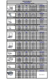
Coating Thickness Software for Eagle µ-EDXRF Systems
Coating Thickness Software for Eagle µ-EDXRF Systems
Coating Thickness Software for Eagle µ-EDXRF Systems

You also want an ePaper? Increase the reach of your titles
YUMPU automatically turns print PDFs into web optimized ePapers that Google loves.
1.4.4 Multiple Layers <strong>Systems</strong><br />
In multi-layer systems, there are more complications introduced by the very presence of the adjacent layers,<br />
in particular the layers above. The situation <strong>for</strong> a two-layer (double layer) system is illustrated in Figure 8.<br />
Note: The convention in the FunMaster & ReCalib software packages is that the layer most<br />
remote from the base (i.e. at the surface) is designated “layer #1”.<br />
detector<br />
detector<br />
thin coating layer #1<br />
thick coating layer #2<br />
thick coating layer #1<br />
thick coating layer #2<br />
“base”<br />
material<br />
(a)<br />
(b)<br />
Figure 8. Illustrating the consequence of variations in the upper layer’s (#1) thickness and its<br />
influence upon observed intensities <strong>for</strong> underlying layers (e.g. #2).<br />
<strong>Thickness</strong> of sub-layer #2 is unchanged in Figures 8a & 8b, but the observed intensity (indicated by the<br />
width of the emergent beam) in 8b is lower because the increased thickness of the top layer #1.<br />
The variable thickness of layer #1 affects both:<br />
a. the amount of incident radiation reaching layer #2 and hence available to excite its analyte line(s)<br />
[an example of “Primary absorption”]<br />
b. the degree of additional absorption of the emergent analyte beam from layer #2 and hence it’s<br />
observed intensity [an example of “Secondary absorption”].<br />
These effects are additional to the self absorption effects of the analyte line within its own layer.<br />
FunMaster generated calibrations <strong>for</strong> multi-layer systems first determine the relevant calibrations <strong>for</strong> each<br />
individual layer’s element/alloy. It then determines how these calibrations <strong>for</strong> the sub-layer components will<br />
be modified by the presence and/or variable thickness of any upper layers. Typically, the presence of upper<br />
layers reduces the working thickness-range of the underlying layers.<br />
The standard-less procedures within FunMaster yield calibration accuracies of typically 5% <strong>for</strong> the first top<br />
layer. Errors in calibrations of underlying layers will be larger. Contributions to errors include uncertainties<br />
in the Fundamental Parameters, assumptions in the model, as well as the possibly incomplete description of<br />
the instrument’s geometry. The recalibration procedure to be found in the stand alone ReCalib routine<br />
makes it possible to reduce the influence of the <strong>for</strong>egoing errors and improve overall accuracy.<br />
The recalibration procedure can become quite involved especially <strong>for</strong> multi-layer systems and alloy layers. It<br />
is recommended, where data from suitable reference standards is available, to always fine tune the<br />
theoretical calibration parameters computed within FunMaster by using such data within the ReCalib routine.<br />
Any FunMaster generated calibration should be verified using the ReCalib routine.<br />
1.4.1 “Bulk Sample” and “Thin Film” Intensities 14