


Create successful ePaper yourself
Turn your PDF publications into a flip-book with our unique Google optimized e-Paper software.
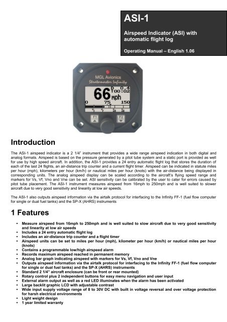
<strong>ASI</strong>-1<br />
Airspeed Indicator (<strong>ASI</strong>) with<br />
automatic flight log<br />
Operating <strong>Manual</strong> – English 1.06<br />
Introduction<br />
The <strong>ASI</strong>-1 airspeed indicator is a 2 1/4” instrument that provides a wide range airspeed indication in both digital and<br />
analog formats. Airspeed is based on the pressure generated by a pitot tube system and a static port is provided as well<br />
for use by high speed aircraft. In addition, the <strong>ASI</strong>-1 provides a 24 entry automatic flight log that stores the duration of<br />
each of the last 24 flights, an air-distance trip counter and a current flight timer. Airspeed can be indicated in statute miles<br />
per hour (mph), kilometers per hour (km/h) or nautical miles per hour (knots) with the air-distance being displayed in<br />
corresponding units. The analog airspeed display can be scaled according to the aircraft’s flying speed range and<br />
markers for Vs, Vf, Vno and Vne can be set. <strong>ASI</strong> sensitivity can be calibrated by the user to cater for errors caused by<br />
pitot tube placement. The <strong>ASI</strong>-1 instrument measures airspeed from 16mph to 250mph and is well suited to slower<br />
aircraft due to very good sensitivity and linearity at low air speeds.<br />
The <strong>ASI</strong>-1 also outputs airspeed information via the airtalk protocol for interfacing to the Infinity FF-1 (fuel flow computer<br />
for single or dual fuel tanks) and the SP-X (AHRS) instruments<br />
1 Features<br />
• Measure airspeed from 16mph to 250mph and is well suited to slow aircraft due to very good sensitivity<br />
and linearity at low air speeds<br />
• Includes a 24 entry automatic flight log<br />
• Includes an air-distance trip counter and a flight timer<br />
• Airspeed units can be set to miles per hour (mph), kilometer per hour (km/h) or nautical miles per hour<br />
(knots)<br />
• Contains a programmable low/high airspeed alarm<br />
• Records maximum airspeed reached in permanent memory<br />
• Analog bar graph indicating airspeed with markers for Vs, Vf, Vno and Vne<br />
• Outputs airspeed information via the airtalk protocol for interfacing to the Infinity FF-1 (fuel flow computer<br />
for single or dual fuel tanks) and the SP-X (AHRS) instruments<br />
• Standard 2 1/4” aircraft enclosure (can be front or rear mounted)<br />
• Rotary control plus 2 independent buttons for easy menu navigation and user input<br />
• External alarm output as well as a red LED illuminates when the alarm has been activated<br />
• Large backlit graphic LCD with adjustable contrast<br />
• Wide input supply voltage range of 8 to 30V DC with built in voltage reversal and over voltage protection<br />
for harsh electrical environments<br />
• Light weight design<br />
• 1 year limited warranty
<strong>ASI</strong>-1 Operating <strong>Manual</strong> Page 2<br />
2 <strong>ASI</strong>-1 Layout<br />
Backlit Graphic LCD Display:<br />
Contrast and backlight can be adjusted<br />
in the menu system<br />
LED Alarm:<br />
The red LED will illuminate if the<br />
airspeed alarm set-point has been<br />
exceeded<br />
Pressure Ports:<br />
Pressure ports connect<br />
to static and pitot tubes<br />
Up/F1 Button:<br />
Up button in menu system<br />
Start/Stop flight in normal<br />
mode<br />
Harness:<br />
Harness connects to<br />
power<br />
Down/F2 Button:<br />
Down button in menu<br />
system<br />
Reset air distance trip<br />
counter in normal mode<br />
Rotary Control (Up/Down) & Enter Button:<br />
Press the rotary control during normal mode to access the menu system. Rotate<br />
anti/clockwise for up/down menu scrolling. During normal mode rotating the rotary control<br />
will display the permanent memory maximum recorded airspeed.<br />
3 Main Display<br />
Air distance trip<br />
counter<br />
Digital airspeed<br />
Duration of flight<br />
since take-off<br />
Analog airspeed display<br />
Airspeed units<br />
Airspeed markers<br />
Airspeed alarm<br />
Maximum airspeed<br />
reached marker
<strong>ASI</strong>-1 Operating <strong>Manual</strong> Page 3<br />
3.1 Start/Stop Flight Display<br />
Press the F1 key during the normal display mode to manually start/stop a flight. This key is only active if the <strong>ASI</strong>-1 is<br />
setup to select the manual flight option under the “Flight Log” setup menu.<br />
3.2 Reset Air Distance Trip Counter Display<br />
This display can be accessed by pressing the F2 key during the normal display mode. Pressing the F1 key will reset the<br />
air distance trip counter to zero. Pressing any other key will cause the <strong>ASI</strong>-1 to resume to the normal display mode. The<br />
air distance trip counter can still be reset manually even if the pilot selects the automatic resetting of the air distance trip<br />
counter.<br />
Note: The air distance trip counter measures distance flown through the air. This is not the same as<br />
distance flown over the ground unless you are flying at sea level at zero wind speed. The air<br />
distance shown is subject to under reading at altitude due to decreased air density.<br />
3.3 Maximum Airspeed Display<br />
This display can be accessed by rotating the rotary control either clockwise or anticlockwise during the normal display<br />
mode. Pressing the F1 key again will reset the maximum airspeed to the current airspeed. Pressing any other key will<br />
cause the <strong>ASI</strong>-1 to resume back to the normal display mode. To avoid false recordings, the maximum airspeed function is<br />
only activated 10 seconds after the instrument has powered up.<br />
Note: The maximum airspeed is stored in non-volatile memory and is<br />
recalled on power-up.
<strong>ASI</strong>-1 Operating <strong>Manual</strong> Page 4<br />
4 Menu System<br />
Pressing the rotary control button during the normal display mode will cause the <strong>ASI</strong>-1 to enter the menu system. Use the<br />
up/down keys or the rotary control to navigate through the menu system.<br />
Note: (ADC Values and Calibrate Menus are only visible when powering up the unit and pressing the<br />
Rotary Control). The text “CALIBRATE” will appear on the intro screen when entering this mode.<br />
Warning: The Calibrate Menu is for technical personnel only. Changing any values in this menu may<br />
cause the instrument to display incorrect information, and may require the instrument to be returned to<br />
the factory for recalibration.<br />
4.1 Exit Menu<br />
Pressing the rotary control on this menu item will cause the <strong>ASI</strong>-1 to exit the menu system. All<br />
changes made during navigation of the menu system will be saved in non-volatile memory on exiting<br />
the menu system. If you remove power before exiting the menu the instrument will not save any<br />
changes.<br />
4.2 Flight Log<br />
The <strong>ASI</strong>-1 uses the following algorithm to determine if a flight is in progress (Detect Mode): If<br />
airspeed is greater than the preset flight take off airspeed for a duration of 60 seconds or more, a<br />
flight is started with a logbook entry. The flight ends if airspeed falls below the preset flight take-off<br />
airspeed for 30 seconds. During a flight the logbook cannot be viewed.<br />
The above algorithm ensures that touch-and-goes will not result in the end of a flight and a logbook<br />
entry. Should the instrument be switched off during a flight, this will end the flight and the log will<br />
reflect the time until the instrument was switched off. Should the instrument be switched on again during a flight, a new<br />
flight will start for logging purposes.<br />
Move the highlight over the “DONE” menu item and press the rotary button to return to the main<br />
menu
<strong>ASI</strong>-1 Operating <strong>Manual</strong> Page 5<br />
Select this function to view the flight log. The flight log contains the duration of<br />
each of the last 24 logged flights. Duration is displayed in hours and minutes.<br />
Use the up/down keys or the rotary control to navigate through the log. Empty<br />
log entries are shown as “-----“.<br />
Note: You cannot select this function while a flight is in progress.<br />
Pressing the F1 key will erase all the flight log entries<br />
Select if you would like the hour to be displayed in decimal fractions (0-99) or minutes (0-59).<br />
This setting influences the current flight time display and the flight log.<br />
Select whether you want the <strong>ASI</strong>-1 to automatically detect a flight or whether the pilot must press the<br />
F1 key to start/stop a flight.<br />
This menu option is only shown if the “detect” flight mode is selected. Enter the airspeed that you<br />
want to start a flight log.<br />
4.3 Display Setup<br />
Move the highlight over the “DONE” menu item and press the rotary button to return to the main<br />
menu<br />
Select this menu option to adjust the display contrast<br />
Select this menu option to turn the backlight on or off
<strong>ASI</strong>-1 Operating <strong>Manual</strong> Page 6<br />
4.4 Airspeed Setup<br />
All the airspeed parameters can be setup here<br />
Move the highlight over this menu option and press the rotary button to return to the main menu<br />
This setup allows your instrument to measure the zero airspeed reading of the<br />
airspeed sensor and set a calibration value internally for this. This is<br />
equivalent to some mechanical airspeed indicators that have an adjustment to<br />
set the needle to zero when the aircraft is not moving. You would use this<br />
function occasionally if you see an airspeed reading when the aircraft is at<br />
rest. This may be caused by aging of the built in pressure sensor or related electronics. When this function is performed<br />
make sure that there is no air flow into the pitot tube as this would result in an incorrect internal calibration.<br />
Pressing the F1 key will zero the airspeed sensor.<br />
Select the maximum value that you want the airspeed analog bar graph display to show. This can<br />
give you increased display resolution.<br />
Select whether you want the low air speed alarm to be turned on or off. The low airspeed alarm is<br />
only activated once a flight has started.<br />
Enter the low airspeed set-point for when the alarm must activate. Any speed below this value will<br />
activate the alarm.<br />
Select whether you want the high air speed alarm to be turned on or off.<br />
Enter the high airspeed set-point for when the alarm must activate. Any speed above this value will<br />
activate the alarm.<br />
Select your preferred units. You can select statute miles, kilometers or nautical miles. According<br />
to this selection your airspeed will be indicated in mph, km/h or knots.<br />
This function can be used to select the signal filter time constant. Selections are “fast” or “slow”. This<br />
selection influences the rate at which your <strong>ASI</strong> can change its reading. If you have an installation<br />
that suffers from strong turbulence at the pitot tube, select “slow”. If you have a very clean airflow in<br />
front of the pilot tube you can select “fast” which will give you a faster response to airspeed changes.<br />
Select if you want the air-distance counter to reset automatically at the start of a flight or if you want<br />
to reset manually only.<br />
Note: You can reset the air distance counter at any time regardless of this setting.
<strong>ASI</strong>-1 Operating <strong>Manual</strong> Page 7<br />
You can set up a marker on the analog airspeed display for Vs. Vs would be your stall speed or<br />
minimum safe flying speed. You may also choose to use this marker as your approach speed.<br />
You can set up a marker on the analog airspeed display for Vf. Vf is your maximum flap speed.<br />
You can set up a marker on the analog airspeed display for Vno. Vno is the maximum<br />
maneuvering speed or top end of the normal operating speed range.<br />
You can set up a marker on the analog airspeed display for Vne. Vne is the never exceed maximum<br />
speed.<br />
4.5 ADC Values<br />
Note: This menu item is for technical personnel only, and is not displayed during the normal<br />
operation of the instrument. Please see section 4 above on how to access this menu item.<br />
This menu displays the ADC values that have been read from the pressure sensor.<br />
4.6 Calibrate<br />
Note: This menu item is for technical personnel only, and is not displayed during the normal<br />
operation of the instrument. Please see section 4 above on how to access this menu item. Consult<br />
your local dealer or factory before entering this menu.<br />
This function is used to calibrate your airspeed indicator. During the factory calibration a factor has<br />
been determined and entered here that will give you accurate airspeed, provided your pitot tube is<br />
not influenced by pressure effects caused by airflow around your airframe. The calibration is<br />
displayed in % of the reading, you can increase or decrease the reading if required to help cancel<br />
out under or over reading of the airspeed indicator on your aircraft. The original calibration factor has<br />
been written onto the back of your instrument.
<strong>ASI</strong>-1 Operating <strong>Manual</strong> Page 8<br />
5 Loading Factory default settings<br />
Pressing and holding the F1 and F2 key simultaneously on power up will cause the <strong>ASI</strong>-1 to load preprogrammed factory<br />
default settings. The following screen will be displayed:<br />
6 Operating the alarms<br />
If the alarm is activated, the corresponding item on the display will flash. At the same time the externally available alarm<br />
switch will close. The switch will remain closed until any button is pressed to acknowledge the alarm or until the<br />
condition(s) that activated the alarm no longer exist. The alarm output can be used to switch an external alarm indicator.<br />
The external alarm switch is an open collector transistor switch to ground with a maximum rating of 0.5A DC. It is possible<br />
to wire the alarm contacts of several Stratomaster instruments in parallel should this be desired. To avoid false activation<br />
of the alarms, the alarm function is only active 10 seconds after the instrument has powered up.<br />
7 Cleaning<br />
The unit should not be cleaned with any abrasive substances. The screen is very sensitive to certain cleaning materials<br />
and should only be cleaned using a clean, damp cloth.<br />
Warning: The <strong>ASI</strong>-1 is not waterproof, serious damage could occur if the unit is exposed to<br />
water and/or spray jets.<br />
8 Specifications<br />
Operating Temperature Range<br />
Storage Temperature Range<br />
Humidity<br />
Power Supply<br />
Current Consumption<br />
Display<br />
ADC<br />
Dimensions<br />
Enclosure<br />
Weight<br />
Alarm contact current rating<br />
Non-volatile memory storage<br />
Airspeed range<br />
Airspeed resolution<br />
Measurement accuracy<br />
Airtalk protocol<br />
-10ºC to 50ºC (14ºF to 122ºF)<br />
-20ºC to 80ºC (-4ºF to 176ºF)<br />
<strong>ASI</strong>-1 Operating <strong>Manual</strong> Page 9<br />
9 Installation<br />
Connect a pitot tube to the “pressure port” and if required connect the static port. Pitot tubes are found in a large variety at<br />
your aircraft parts shop, in mail order catalogs or you can make your own. Contrary to popular belief, pitot tubes are not<br />
carefully designed and calibrated but are simple orifices or tubes that get pointed in the direction that you are flying. The<br />
forward movement of the aircraft causes air to dam inside the pitot tube. This increases the pressure inside the tube. Most<br />
small aircraft such as ultralights or microlights do not require a connection to a static port. In these cases, simply leave the<br />
static port open. Ensure however that the static port does not receive pressurized air due to the forward movement of the<br />
aircraft. Be especially critical of your pod or panel if you do not use a static port. Any build up of a pressure differential due<br />
to ram air or suction can lead to large errors of the indicated airspeed. Static ports are usually mounted at a strategic<br />
position on the rear side of the aircraft fuselage for faster, pressurized aircraft. Suitable pitot tubes can be made from a<br />
short piece of hollow aluminum or copper piping. Length and diameter are not important. Ensure that the front of the pitot<br />
tube has a suitable chamfer if you use thick walled tubing or you may introduce a speed reading error if you have a faster<br />
aircraft.<br />
Example cross-section of thick walled pitot tube.<br />
Suitable connection hose for both pitot tube and static port can be obtained from a hardware store or even a pet shop.<br />
Good quality tubing is often used for fish tanks and it has just the right diameter.<br />
Please note that this kind of tubing is not advised for pressurized aircraft. In this case you would need to obtain aircraft<br />
grade tubing of suitable diameter. You would also have to use hose clamps to fasten the hose onto the <strong>ASI</strong>-1 pitot and<br />
static ports. The <strong>ASI</strong>-1 allows you to calibrate the airspeed reading. This is done under the “Calibrate” menu item. The<br />
main reason for this is to be able to remove errors introduced due to the airflow around your aircraft which may have an<br />
effect on your pitot tube pressure.<br />
9.1 <strong>ASI</strong>-1 DB9 Cable connections<br />
9.2 Pressure Port Dimensions<br />
DB 9 Pin Color Function<br />
1 Black Ground<br />
4 NC Airtalk communication<br />
Used for firmware upgrading and interfacing<br />
to the FF-1/SP-X (Airtalk speed message)<br />
6 Red 8-30Vdc power<br />
9 White Alarm Output<br />
A<br />
B<br />
C<br />
D<br />
Inches<br />
Millimeters<br />
Min Max Min Max<br />
0.248 0.278 6.30 7.06<br />
0.420 0.440 10.67 11.18<br />
0.182 0.194 4.62 4.93<br />
0.310 0.330 7.87 8.38
<strong>ASI</strong>-1 Operating <strong>Manual</strong> Page 10<br />
9.3 Connection Diagram<br />
The use of an external 1A fuse is recommended. Connect the supply terminals to your aircrafts power supply. The <strong>ASI</strong>-1<br />
can be used on both 12V and 24V without the use of any pre-regulators. Ensure that the supply voltage will not drop<br />
below 8V during operation as this may result in incorrect voltage and or current readings.<br />
10 Warranty<br />
This product carries a warranty for a period of one year from date of purchase against faulty workmanship or defective<br />
materials, provided there is no evidence that the unit has been mishandled or misused. Warranty is limited to the<br />
replacement of faulty components and includes the cost of labour. Shipping costs are for the account of the purchaser.<br />
Damage as a result of applying excessive pressure to the pressure ports are excluded from warranty.<br />
Note: Product warranty excludes damages caused by unprotected, unsuitable or incorrectly wired<br />
electrical supplies and/or sensors, and damage caused by inductive loads.
<strong>ASI</strong>-1 Operating <strong>Manual</strong> Page 11<br />
11 Disclaimer<br />
Operation of this instrument is the sole responsibility of the purchaser of the unit. The user must make themselves familiar<br />
with the operation of this instrument and the effect of any possible failure or malfunction.<br />
This instrument is not certified by the FAA. Fitting of this instrument to certified aircraft is subject to the rules and<br />
conditions pertaining to such in your country. Please check with your local aviation authorities if in doubt. This instrument<br />
is intended for ultralight, microlight, homebuilt and experimental aircraft. Operation of this instrument is the sole<br />
responsibility of the pilot in command (PIC) of the aircraft. This person must be proficient and carry a valid and relevant<br />
pilot’s license. This person has to make themselves familiar with the operation of this instrument and the effect of any<br />
possible failure or malfunction. Under no circumstances does the manufacturer condone usage of this instrument for IFR<br />
flights.<br />
The manufacturer reserves the right to alter any specification without notice.<br />
Other instruments in the Stratomaster Infinity series<br />
ALT-1 Precision encoding altimeter and vertical speed indicator<br />
ALT-2 Precision encoding altimeter and vertical speed indicator with a serial RS232<br />
transponder output<br />
<strong>ASI</strong>-1 Airspeed indicator (<strong>ASI</strong>) with automatic flight log<br />
ASX-1 Encoding aviation altimeter with serial output and airspeed indicator (<strong>ASI</strong>)<br />
AV-1 Artificial horizon and magnetic compass indicator<br />
BAT-1 Battery voltage and current monitor<br />
E-3 Universal engine monitor<br />
FF-1 Fuel Computer (single or dual fuel tanks)<br />
GF-1 +-10G tilt compensated dual range G-force meter<br />
MAP-1 Manifold pressure and RPM Indicator<br />
RV-1 Universal engine RPM and rotor RPM Indicator<br />
RV-2 Universal turbine RPM / RPM factor display<br />
RTC-2 Aviation real time clock (RTC) and outside air temperature (OAT) display<br />
TC-1 4-Channel thermocouple indicator<br />
TP-1 Universal temperature and pressure gauge


