TCP/IP Converter DDS EX-9132 Operation Manual for 8051 Series
TCP/IP Converter DDS EX-9132 Operation Manual for 8051 Series
TCP/IP Converter DDS EX-9132 Operation Manual for 8051 Series

You also want an ePaper? Increase the reach of your titles
YUMPU automatically turns print PDFs into web optimized ePapers that Google loves.
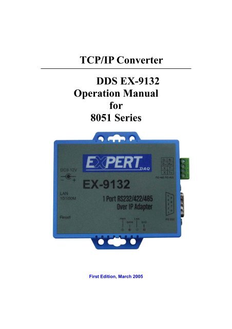
<strong>TCP</strong>/<strong>IP</strong> <strong>Converter</strong><br />
<strong>DDS</strong> <strong>EX</strong>-<strong>9132</strong><br />
<strong>Operation</strong> <strong>Manual</strong><br />
<strong>for</strong><br />
<strong>8051</strong> <strong>Series</strong><br />
First Edition, March 2005
Table of Contents<br />
1. Introduction ……………………………………………… 3<br />
Overview ………………………………………………… 4<br />
Package Checklist ………………………………………… 5<br />
Block Diagram …………………………………………… 6<br />
Features …………………………………………………… 7<br />
Product Specifications …………………………………… 8<br />
2. <strong>Converter</strong> Description & Installation ……………… 10<br />
Product Panel Views ……………………………………… 10<br />
Top Side …………………………………………………… 10<br />
Left Side ………………………………………………… 11<br />
Right Side …………………………………………………… 12<br />
Rear Side ………………………………………………… 12<br />
Reset ……………………………………………………… 13<br />
LED Indicators …………………………………………… 13<br />
Wiring Architecture ……………………………………… 14<br />
RS-232 …………………………………………………… 14<br />
RS-422/RS-485 …………………………………………… 14<br />
3. <strong>Converter</strong> Configuration …………………………… 16<br />
Initial <strong>IP</strong> Configuration ………………………………… 16<br />
Device Management Utility of ExpertDAQETM ………… 17<br />
Menu “Refresh” …………………………………………… 18<br />
Menu “Config” …………………………………………… 18<br />
Web Console Configuration …………………………… 20<br />
Controller Status ………………………………………… 21<br />
1
Controller Setup ………………………………………… 23<br />
Controller Updated ……………………………………… 29<br />
Factory Default Setting ………………………………… 30<br />
4. Self-Testing ………………………………………………… 31<br />
Hyper Terminal <strong>for</strong> <strong>TCP</strong>/<strong>IP</strong> WinSock ………………… 32<br />
Hyper Terminal <strong>for</strong> COM Port ………………………… 35<br />
Data Transmission ……………………………………… 36<br />
Appendix A - FAQ ………………………………………… 37<br />
Appendix B - Pin Outs and Cable Wiring ………… 38<br />
DC Power Outlet ………………………………………… 38<br />
RJ-45 Pin Assignment …………………………………… 38<br />
RS-232 Pin Assignment ………………………………… 38<br />
RS-232 Wiring Diagram ………………………………… 39<br />
RS-422 Pin Assignment ………………………………… 39<br />
RS-422 Wiring Diagram ………………………………… 39<br />
RS-485 Wiring Diagram ………………………………… 39<br />
2
1<br />
Introduction<br />
Tops CCC Products Co., Ltd. is providing new ways of connecting legacy serial devices to a<br />
Local Area Network (LAN) or Wide Area Network (WAN). <strong>TCP</strong>/<strong>IP</strong> converters are<br />
designed to operate serial ports over 10/100M Ethernet networks. The data is transmitted via<br />
<strong>TCP</strong>/<strong>IP</strong> protocol. There<strong>for</strong>e control is available via Ethernet, Intranet and Internet. <strong>TCP</strong>/<strong>IP</strong><br />
converters are packaged in a plastic case well suited <strong>for</strong> industrial environments. All serial<br />
ports operate in common RS-232 mode , industrial RS-422 and RS-485 modes<br />
configuration.<br />
<strong>TCP</strong>/<strong>IP</strong> converter series is a low-cost, high per<strong>for</strong>mance design. By careful selecting high<br />
quality with competitive prices components in the world, <strong>EX</strong>-<strong>9132</strong> product made network<br />
connectivity possible with af<strong>for</strong>dable cost <strong>for</strong> virtually all kinds of devices.<br />
The <strong>8051</strong> <strong>Series</strong> of <strong>TCP</strong>/<strong>IP</strong> converters consists of 2 models: <strong>EX</strong>-<strong>9132</strong> (1 port <strong>for</strong><br />
RS-232/422/485) is a ready set product and the other <strong>EX</strong>-<strong>9132</strong>-M (1 port <strong>for</strong><br />
RS-232/422/485) is a module product <strong>for</strong> developing purpose by customers.This operation<br />
manual will guide you step by step <strong>for</strong> the various functions of the <strong>TCP</strong>/<strong>IP</strong> converter. For<br />
technical questions E-Mail to support@d-d-.nl<br />
The following topics are covered in this chapter:<br />
□ Overview<br />
□ Package Checklist<br />
□ Block Diagram<br />
□ Product Features<br />
□ Product Specifications<br />
3
Overview<br />
<strong>TCP</strong>/<strong>IP</strong> converters are designed to make your serial devices Internet ready instantly.<br />
<strong>8051</strong> <strong>Series</strong> of <strong>TCP</strong>/<strong>IP</strong> converters makes them the ideal choice <strong>for</strong> connecting your<br />
RS-232 or RS-422/485 serial devices—such as PLCs, meters, and sensors—to an<br />
<strong>IP</strong>-based Ethernet LAN, making it possible <strong>for</strong> your software to access serial devices<br />
anywhere and anytime over a local LAN or the Internet.<br />
<strong>8051</strong> <strong>Series</strong> converters ensure the compatibility of network software that uses a standard<br />
network API (Winsock or BSD Sockets) by providing <strong>TCP</strong> Server Mode, <strong>TCP</strong> Client<br />
Mode, and UDP Mode. <strong>8051</strong> <strong>Series</strong>’ Virtual COM driver, software that works with COM<br />
port can be set up to work over a <strong>TCP</strong>/<strong>IP</strong> network in no time. This excellent feature<br />
preserves your software investment and lets you enjoy the benefits of networking your<br />
serial devices instantly.<br />
<strong>8051</strong> <strong>Series</strong> converters support manual configuration via the handy web browser console<br />
and many protocols including <strong>TCP</strong>, <strong>IP</strong>, UDP, HTTP, DHCP, ICMP, and ARP. They are the<br />
best solution to network your serial devices.<br />
4
Package Checklist<br />
<strong>8051</strong> products are shipped with the following items:<br />
□ 1 unit of <strong>EX</strong>-<strong>9132</strong> <strong>TCP</strong>/<strong>IP</strong> converter<br />
□ Documentation & Software CD<br />
□ Quick Installation Guide<br />
NOTE: Notify your sales representative if any of the above items is missing or damaged.<br />
5
Block Diagram<br />
Low-cost devices usually are equipped with low speed processors and limited memories. In<br />
reality, they are neither having the capability nor practicality to manage complicated network<br />
<strong>TCP</strong>/<strong>IP</strong> protocols. <strong>8051</strong> <strong>Series</strong> is a low cost while providing high per<strong>for</strong>mance network<br />
solution by converting data stream between network <strong>TCP</strong>/<strong>IP</strong> and popular serial port signals.<br />
In stead of processing <strong>TCP</strong>/<strong>IP</strong> packets directly, devices need only deal with those interface<br />
signals, which greatly simplifies the complexity of <strong>TCP</strong>/<strong>IP</strong> network in linkage.<br />
6
Product Features<br />
□<br />
□<br />
Data Conversion between RS-232/422/485 and Ethernet<br />
Convert serial device (RS-232, RS-422, RS-485) data/signal into the <strong>TCP</strong>/<strong>IP</strong> package<br />
data/signal and send them out with the Ethernet DataStream; or convert the <strong>TCP</strong>/<strong>IP</strong><br />
package data/signal into serial device data/signal.<br />
Digital I/O Activating (For OEM only)<br />
Convert the sensors’ statuses into the <strong>TCP</strong>/<strong>IP</strong> package data and send them out with the<br />
Ethernet DataStream; or use the <strong>TCP</strong>/<strong>IP</strong> package data to activate/deactivate the specified<br />
digital outputs / inputs.<br />
Note: This function is <strong>for</strong> OEM only. Please contact your sales representative <strong>for</strong><br />
further in<strong>for</strong>mation.<br />
□<br />
□<br />
□<br />
□<br />
□<br />
□<br />
Dynamic <strong>IP</strong> Configuration<br />
Support DHCP client mode, simplifying network address configuration and management.<br />
Dual LAN Speed<br />
Support 10/100 Mbps Ethernet, auto-detected.<br />
Server / Client Dual Modes<br />
<strong>8051</strong> <strong>Series</strong> can be configured as network server or network client. In the client mode, it<br />
can be installed in network which is protected by NAT router or firewall, without the<br />
need of a real <strong>IP</strong> address.<br />
Web-based Setup<br />
Parameters setup are based on HTTP protocol by using standard browsers (IE and<br />
Netscape). No special software would be required.<br />
Built-in Security Control<br />
Protected by both setup password and access password to prevent intruders.<br />
Firmware Remote Update<br />
Firmware can be updated directly via Ethernet network to keep up with latest network<br />
standards.<br />
7
Product Specifications<br />
• CPU : 8-bits <strong>8051</strong> , 36.864 MHz<br />
• RAM : 32K Bytes SRAM<br />
• ROM : 64 K Bytes<br />
• Ethernet<br />
● Port Type : RJ-45 Connector<br />
● Speed : 10 /100 M bps ( Auto Detecting )<br />
● Protocol : ARP, <strong>IP</strong>, ICMP, UDP, <strong>TCP</strong>, HTTP, DHCP<br />
● Mode : <strong>TCP</strong> Server/Client ; UDP<br />
● Setup : HTTP Browser Setup (IE & Netscape), RS-232 Console<br />
● Security : Setup Password & Connecting Password<br />
● Protection : Built-in 1.5KV Magnetic Isolation<br />
• Serial Port<br />
● No. of Ports : RS-232 / RS-422/RS-485 * 1 Port<br />
● Port Type : DB9 male <strong>for</strong> RS-232 and Terminal Block <strong>for</strong> RS-422/485<br />
● Speed : 300 bps115.2k bps<br />
● Parity : None , Odd , Even<br />
● Data Bit : 7 , 8<br />
● Stop Bit : 1 , 2<br />
● RS-232 Signals : Rx , Tx , GND , RTS , CTS , DTR , DSR , DCD<br />
● RS-422 Signals : Rx+ , Rx- , Tx+ , Tx- (Surge Protection)<br />
● RS-485 Signals : Data+ , Data- (Surge Protection)<br />
● Built-in RS422/RS485 Terminal Resistor<br />
• Digital I/O Port<br />
TTL Digital I/O * 7<br />
• 15KV ESD <strong>for</strong> all signal<br />
8
• Watch Dog Function<br />
• Firmware On-line Updated Via Ethernet<br />
• Power : DC 9 – 12 V , 500mA<br />
• LED Lamp : Model <strong>EX</strong>-<strong>9132</strong><br />
• Environment :<br />
PWR (Green)<br />
DATA (Red-Blink during data transferring and receiving)<br />
LAN (Red)<br />
SYS (Red-Blink)<br />
Operating Temperature : 0 60<br />
Storage Temperature : -10 70<br />
• Dimensions : <strong>EX</strong>-<strong>9132</strong> : 90 * 90 * 25 mm ( W * D * H )<br />
• WEIGHT : 110 gm<br />
• RoHS :Compliant with RoHS<br />
• Regulatory Approvals :<br />
EMC : FCC Class A, CE Class A<br />
• WARRANTY : 1 year<br />
9
<strong>Converter</strong> Description & Installation<br />
2<br />
Product Panel Views<br />
Top Side<br />
DC-In<br />
Power Outlet<br />
Serial I/O Port<br />
RS-485/RS-422<br />
LAN<br />
Reset<br />
Serial I/O Port<br />
RS-232<br />
LED Indicators<br />
10
Left Side<br />
Power Supply<br />
<strong>EX</strong>-<strong>9132</strong> <strong>TCP</strong>/<strong>IP</strong> supports 9 ~ 12V DC input voltage at a current of 500 mA.<br />
Connect the power line into the power connector (inner terminal<br />
positive/outer terminal negative) of <strong>EX</strong>-<strong>9132</strong> <strong>TCP</strong>/<strong>IP</strong> converter and insert<br />
the power adapter into the socket. If power is properly supplied, the<br />
green LED labeled with “PWR” will be on.<br />
DC-In<br />
Power Outlet<br />
LAN<br />
Reset Button<br />
LAN Port<br />
The connector <strong>for</strong> network is the usual RJ45. Simply connect it to your network<br />
switch or Hub. When the connection is made, the LAN LED indicator will light.<br />
When data traffic occurs on the network, red DATA LED indicator will blink during<br />
data transferring and receiving.<br />
11
Reset Button<br />
If by any chance, you <strong>for</strong>get the setup password, or have incorrect settings making<br />
<strong>EX</strong>-<strong>9132</strong> <strong>TCP</strong>/<strong>IP</strong> converter inoperable. First, turn off the power. Second, use any point<br />
tip to push this button and hold it to turn on the power at the same time <strong>for</strong> 5 second.<br />
All the parameters will be reset to the factory default.Reset Button<br />
Right Side<br />
RS-485/RS-422<br />
RS-232<br />
Serial I/O Port of RS-232/RS-422/RS-485<br />
Connect the serial data cable between the converter and the serial device. Follow the<br />
parameter setup procedures to configure the converter (see the following chapters ).<br />
12
LED Indicators<br />
PWR (Green)<br />
Power indicator (When the power is on, the LED will be on.)<br />
DATA (Red)<br />
Data sent & received indicator (When data are sending and receiving to the network, the<br />
LED will blink.)<br />
10/100 (Green)<br />
Network signal indicator, when the LAN signal is detected and then, the LED will be on.<br />
LAN (Red)<br />
Device statues indicator (When <strong>EX</strong>-<strong>9132</strong> <strong>TCP</strong>/<strong>IP</strong> converter is operated in normal statues,<br />
the LED will blink once per second.)<br />
13
Wiring Architecture<br />
RS-232 Wiring Architecture<br />
RS-422/RS-485 Wiring Architecture<br />
14
When you finish the steps mentioned above and the LED indicators are as shown,<br />
the converter is installed correctly. You can use the Setup Tool<br />
“ExpertDAQETM .exe” to setup the <strong>IP</strong> Address.<br />
To proceed the advanced parameter setup, please use a web browser (IE or<br />
Netscape) to continue the detailed settings.<br />
15
3<br />
<strong>Converter</strong> Configuration<br />
Initial <strong>IP</strong> Configuration<br />
When setting up your converter <strong>for</strong> the first time, the first thing you should do is configure<br />
the <strong>IP</strong> address. This chapter introduces the method to configure the device server’s <strong>IP</strong><br />
address. For more details about network settings, see “Web Console Configuration”. in<br />
next sub section.<br />
For quick and easy start , We suggest you to reference “Quick Installation Guide” manual.<br />
The following topics are covered in this chapter:<br />
□ Device Management Utility<br />
□ Refresh<br />
□ Exit<br />
□ ExpertDAQETM Config<br />
16
Device Management Utility<br />
On PC we provide a Device Management Utility named ExpertDAQETM which is an<br />
executable program in Windows 32 bit environments. ExpertDAQETM Setup Tool is<br />
used to detect and setup the installed converters. It uses UDP broadcast packets to<br />
query and configure converters on the network.<br />
When you activate the tool, it will detect the existence of the installed converters and<br />
depict the converters’ status such as <strong>IP</strong> address, Subnet Mask, MAC Address, and<br />
Device ID (see Figure 3.1). The Setup Tool only can setup one converter at a time.<br />
Thus if there are more than one converter on the network, please shut down or<br />
disconnect other converters. Otherwise the ExpertDAQETM can not detect the converter.<br />
Other similar issues, you may reference to Q&A in Appendix A.<br />
Due to the nature of broadcast UDP packets, ExpertDAQETM has following<br />
characteristics:<br />
□ Broadcast packets aren’t limited by subnet. Even if the <strong>IP</strong> address of the converters<br />
and the computer running ExpertDAQETM do not belong to the same subnet, it<br />
still works fine.<br />
□ Broadcast packets can not pass routers. ExpertDAQETM can only be used to<br />
monitor devices with computer running ExpertDAQETM in the same segment of<br />
local area network<br />
17
Refresh<br />
Refresh the status. ExpertDAQETM will send another query to get updated<br />
in<strong>for</strong>mation.<br />
Note: Always run the “View-> Refresh” after any data change.<br />
Exit<br />
Exit from the program<br />
ExpertDAQETM Config<br />
Moving the mouse cursor onto the desired device that displaying in in<strong>for</strong>mation window<br />
Clicking the left button of mouse to invoke the ExpertDAQETM Config.<br />
18
Note : Because ExpertDAQETM uses broadcast UDP packets, <strong>for</strong> the sake of<br />
security, it allows configuration only when device's setup password is<br />
empty.<br />
Assign an <strong>IP</strong> Address with the same Subnet Mask of your computer, avoiding any<br />
<strong>IP</strong> conflict with other network devices.<br />
When you press [Setup] button, the <strong>IP</strong> address will be refreshed in 2~3 seconds.<br />
19
Web Console Configuration<br />
In addition to basic <strong>IP</strong> address and subnet mask, specific device settings can be set<br />
through HTTP protocol with popular browsers, e.g. Internet Explorer, Netscape,<br />
etc. Setup of the converters is as easy as surfing on WWW, no special software<br />
will be required. Press [Alt]+[Enter] or select [Device Settings] in the [Config]<br />
menu, will open a new window in browser to login into the device.<br />
Alternatively, if the <strong>IP</strong> address of the converter is already known, you can connect<br />
to the converter directly by providing its <strong>IP</strong> address in the URL field of browsers.<br />
The following topics are covered in this chapter:<br />
□ Controller Status<br />
● The Login Page<br />
● Field Description<br />
□ Controller Setup<br />
● The Setup Page<br />
● Field Description<br />
□ Controller Updated<br />
□ Factory Default Setting<br />
20
Controller Status<br />
The Login Page<br />
<br />
<br />
<br />
<br />
“<br />
”<br />
□ Open your browser. This chapter will use IE as an example.<br />
□ In the browser URL field, type the <strong>IP</strong> address of the converter directly and<br />
press ENTER. (The <strong>IP</strong> address is what you set using the Device Management<br />
Utility.)<br />
□ The “Controller Status” page will be shown (see Figure 3.6).<br />
(Figure 3.6)<br />
21
Field Description<br />
□<br />
System time elapsed<br />
The time elapsed since start of this device in [Day Hour : Minute : Second]<br />
<strong>for</strong>mat. This in<strong>for</strong>mation can be useful in identifying the reliability of system.<br />
□<br />
Firmware version<br />
<strong>Converter</strong> firmware is identified by date code. This in<strong>for</strong>mation will be<br />
required in looking <strong>for</strong> technical support.<br />
□<br />
Serial number<br />
<strong>Converter</strong> is consisted “Type Number (5 digits) and an unique MAC (Media<br />
Access Control) address used by Ethernet in hex <strong>for</strong>mat, 8 digits.<br />
□<br />
Password(Setup Login)<br />
This field is the administration password <strong>for</strong> authentication. Factory default is<br />
“empty”. However, it is not recommended to leave it empty in field operation.<br />
If you could not login, it means you have to key in the password. If you do not<br />
know the password you can turn off the power and then use any point tip to<br />
push “Reset” button and hold it to turn on the power at the same time <strong>for</strong> 5<br />
seconds. The password will be reset to the factory default as “empty”.<br />
<strong>EX</strong>-<strong>9132</strong> <strong>TCP</strong>/<strong>IP</strong> converter uses the same password protection mechanism<br />
commonly used in Windows NT or UNIX. If there are more than “3<br />
consecutive failures” in password check during login, the login function will<br />
be disabled <strong>for</strong> “15 minutes”. During this 15 minutes period, even if you<br />
supply correct password, login will not proceed. This prevents intruders from<br />
finding the password by computer generated program.<br />
22
Controller Setup<br />
□<br />
The Setup Page<br />
Type the correct password in the “Password” field and click the [Login] button in<br />
the “Controller Status” page, then the “Controller Setup” page will appear (see<br />
Figure 3.7).<br />
Note: If you <strong>for</strong>get the password or can’t login successfully, please contact the<br />
manufacturer directly.<br />
(Figure 3.7)<br />
23
□<br />
Field Description<br />
□<br />
<strong>IP</strong> Address<br />
The <strong>IP</strong> address of <strong>EX</strong>-<strong>9132</strong> <strong>TCP</strong>/<strong>IP</strong> converter, 4 digits separated by '.' Don’t<br />
let it conflict with the other devices on the network.<br />
If DHCP client mode is enabled and there's a DHCP server on the network, this<br />
field will be assigned by DHCP server automatically.<br />
□<br />
Subnet mask<br />
Subnet mask of the network <strong>EX</strong>-<strong>9132</strong> <strong>TCP</strong>/<strong>IP</strong> converter has connected to.<br />
“255.255.255.0” is usually used <strong>for</strong> small network, “255.255.0.0” <strong>for</strong> larger<br />
network, 4 digits separated by '.'<br />
If your <strong>IP</strong> address is provided by an ISP or the internal network administrator,<br />
please inquire of them that in<strong>for</strong>mation and type it correctly.<br />
If DHCP client mode is enabled and there's a DHCP server on the network, this<br />
field will be assigned by DHCP server automatically.<br />
□<br />
Gateway address<br />
Gateway or Router <strong>IP</strong> address. 'Gateway' is a device which connects local<br />
network to external network. If you need to communicate with other networks<br />
or your device owns a real <strong>IP</strong> address on the internet, please inquire of them that<br />
in<strong>for</strong>mation and type it correctly. If there's no gateway on the network, just<br />
leave it as “0.0.0.0”.<br />
If DHCP client mode is enabled and there's a DHCP server on the network, this<br />
field will be assigned by DHCP server automatically.<br />
24
□<br />
Network link speed<br />
Ethernet physical link speed. “Auto” means the speed is automatically<br />
selected by the converter. You can also specify “10Mbps” or “100Mbps” to<br />
match the speed of the HUB.<br />
□<br />
DHCP client<br />
DHCP client mode could be enabled/disabled statues. If DHCP is enabled, there<br />
should be a DHCP server on the network. If DHCP is disabled, [<strong>IP</strong> address],<br />
[Subnet mask], and Gateway address] should be manually assigned.<br />
□<br />
Socket port of HTTP setup<br />
The socket port used to conduct the browser setup. Normally, HTTP protocol<br />
use <strong>TCP</strong> port “80” <strong>for</strong> communication. If the field is changed to “81”, the port<br />
“80” will be reserved <strong>for</strong> user's own Web.<br />
To enter the browser setup page, “http://x.x.x.x:81” should be typed <strong>for</strong> socket<br />
port “81” and “http://x.x.x.x” <strong>for</strong> socket port “80”, where “x.x.x.x” is the<br />
converter’s <strong>IP</strong> address..<br />
□<br />
Socket port of serial I/O (RS-232/422/485)<br />
□<br />
Port number<br />
A socket port assigned <strong>for</strong> the serial port. It’s a 16-bit number ,<br />
ranging from 1 to 65535. Because the numbers below 1000 are used<br />
<strong>for</strong> specific purposes (e.g. 80 is <strong>for</strong> HTTP protocol), we suggest you<br />
use the numbers larger than 1000. Generally the port number 4660 is<br />
used <strong>for</strong> the serial communication. However you should specify<br />
different port number <strong>for</strong> each serial port.<br />
□<br />
Socket type<br />
<br />
<br />
<br />
<strong>TCP</strong> Server: <strong>TCP</strong> protocol, passive open, to be connected from the<br />
<strong>TCP</strong> clients.<br />
<strong>TCP</strong> Client: <strong>TCP</strong> protocol, active open, connect to the <strong>TCP</strong> server.<br />
UDP : UDP protocol, connectionless<br />
25
□<br />
Socket port of Digital I/O<br />
□<br />
Port number<br />
A socket port assigned <strong>for</strong> the serial port. It’s a 16-bit number ,<br />
ranging from 1 to 65535. Because the numbers below 1000 are used<br />
<strong>for</strong> specific purposes (e.g. 80 is <strong>for</strong> HTTP protocol), we suggest you<br />
use the numbers larger than 1000. Generally the port number 4660 is<br />
used <strong>for</strong> the serial communication. However you should specify<br />
different port number <strong>for</strong> each serial port.<br />
□<br />
Socket type<br />
<br />
<br />
<br />
<strong>TCP</strong> Server: <strong>TCP</strong> protocol, passive open, to be connected from the<br />
<strong>TCP</strong> clients.<br />
<strong>TCP</strong> Client: <strong>TCP</strong> protocol, active open, connect to the <strong>TCP</strong> server.<br />
UDP: UDP protocol, connectionless<br />
□<br />
Destination setting<br />
□ Destination <strong>IP</strong> address<br />
The server <strong>IP</strong> address and socket port would be connected in <strong>TCP</strong><br />
Client and UDP Client mode <strong>for</strong> a certain server <strong>IP</strong> address.<br />
□<br />
Destination socket port<br />
The server socket port would be connected in <strong>TCP</strong> Client and UDP<br />
Client mode <strong>for</strong> a certain serial port.<br />
□ Connection<br />
The connection can be selected in 2 modes, “Auto” or “<strong>Manual</strong>”.<br />
□<br />
Serial I/O setting<br />
□ Baud rate, parity, data bits, stop bits<br />
Baud Rate: 300 ~ 115200 bps<br />
<br />
Parity: None, Even, Odd<br />
Data Bits: 7, 8<br />
Stop Bit: 1 or 2<br />
26
□<br />
Interface of serial I/O<br />
<br />
<br />
<br />
<br />
<br />
RS232: TxD, RxD <strong>for</strong> data stream, no flow control<br />
RS232 (RTS/CTS): TxD, RxD <strong>for</strong> data stream, RTS/CTS <strong>for</strong> flow<br />
control<br />
RS232 (RTS/CTS, DTR/DSR): TxD, RxD <strong>for</strong> data stream, RTS/CTS<br />
<strong>for</strong> flow control. DTR <strong>for</strong> socket status, DSR <strong>for</strong> socket open/close<br />
control<br />
RS485 (Half duplex): Half duplex RS-485 interface<br />
RS422 (Full duplex): Full duplex RS-422 interface<br />
□<br />
Packet mode of serial input<br />
Packet mode could be in enabled/disabled mode. If packet mode is enabled, the<br />
data input from UART will be deferred until the input buffer is full, or the<br />
converter detects a 10-character packet gap and no more character arrived. The<br />
block waiting time is extended to avoid the splitting of the complete packet.<br />
□<br />
Device ID<br />
User assigned ID number <strong>for</strong> the converter. Available ID is “0 ~ 65535”.<br />
□<br />
Report device ID when connected<br />
In <strong>TCP</strong> mode, if this parameter is enabled, every time when the socket is<br />
connected, <strong>EX</strong>-<strong>9132</strong> <strong>TCP</strong>/<strong>IP</strong> converter will immediately report its device ID in<br />
the following <strong>for</strong>mats:<br />
Serial #1 <br />
Serial #2<br />
Digital I/O <br />
nnnnnA[LF][CR]<br />
nnnnnB[LF][CR]<br />
nnnnnC[LF][CR]<br />
The total length is 8 bytes, where “nnnnn” is a 5-digit device ID assigned by the<br />
user; [LF] is decimal 10; [CR] is decimal 13.<br />
27
□<br />
Setup password<br />
Administration password used to login the “Controller Setup” page. It may be<br />
empty or up to 15 characters long.<br />
□<br />
Access password<br />
During socket connection, Authentication password may be empty or up to 15<br />
characters long. If “Access password” is empty, the authentication is disabled.<br />
Otherwise, the authentication will be conducted. If the authentication fails or<br />
no password is supplied within 10 seconds, the socket will be closed.<br />
28
Controller Updated<br />
Press “Update” Button After you finish the detailed parameter setting. The<br />
converter will save all parameters into internal non-volatile memory and then<br />
reboot <br />
. It takes about 5 seconds to complete the whole process,<br />
and a new login page will be presented <br />
.<br />
<br />
You can re-login and check if all parameters have been correctly saved. If<br />
everything is ok, you can close the browser now.<br />
Note : If the domain of the converter is different from that of the computer<br />
running the browser, the login page won’t appear unless the converter’s<br />
“Gateway Address” has been correctly set.<br />
29
Factory Default Setting<br />
If by chance, you <strong>for</strong>get the setup password, or have incorrect settings making<br />
the converter inoperable, there are two ways to reset the setting and the<br />
following procedures can be used to reset all settings to factory default:<br />
A:<br />
1. you can turn off the power and then use any point tip to push “Reset”<br />
button and hold it to turn on the power at the same time <strong>for</strong> 5 seconds.<br />
The password will be reset to the factory default.<br />
B:<br />
1. Turn off the power of the converter.<br />
2. Use a pin or any point tip to push the screw driver or any conductor to<br />
short DTR and CTS (pin 4 and pin 8 in DB9) of RS232 connector.<br />
3. Turn on the power of the converter and wait 5 seconds.<br />
4. Remove screwed driver or conductor.<br />
30
4<br />
Self-Testing<br />
After completing the wiring and parameter setting, we should verify if the setting is<br />
correct or not. This chapter will introduce how to use a single computer to test if<br />
the converter behaves well.<br />
The operating system can be Windows 95, 98, ME, XP, 2000. The “Hyper<br />
Terminal” utility should be installed on your PC (see Figure 4.1). It can be found<br />
in your Windows installation CD.<br />
The wiring architecture is similar to “RS-232 Wiring” in chapter 2, and the “Serial<br />
Device” is replaced by the PC’s COM 1. The same PC also plays the roll of the<br />
Remote Host.<br />
The following topics are covered in this chapter:<br />
□ Hyper Terminal <strong>for</strong> <strong>TCP</strong>/<strong>IP</strong> WinSock<br />
□ Hyper Terminal <strong>for</strong> COM Port<br />
□ Data Transmission<br />
31
Hyper Terminal <strong>for</strong> <strong>TCP</strong>/<strong>IP</strong> WinSock<br />
Initiate a Hyper Terminal from the Start Menu in Windows (see Figure 4.1), give a<br />
terminal name, choose an icon, and press “OK” button (see Figure 4.2).<br />
(Figure 4.1)<br />
(Figure 4.2)<br />
32
Select “<strong>TCP</strong>/<strong>IP</strong>(Winsock)” option at the “Connect using:” field (see Figure 4.3)<br />
.<br />
(Figure 4.3)<br />
After “OK” button is pressed, Figure 4.4 appears. Enter the converter’s <strong>IP</strong> address (e.g.<br />
192.168.0.10) at the “Host address:” field, and the Socket port number set <strong>for</strong> the Serial<br />
Port 1 at the “Port number:” field (e.g 4660). (The Socket type of the Serial Port 1<br />
should be “<strong>TCP</strong> Server”.)<br />
(Figure 4.4)<br />
33
After “OK” button is pressed, Figure 4.5 appears. If the Hyper Terminal connects with<br />
the converter successfully, the time clock at the “left lower” corner “Connected<br />
hh:mm:ss” will start counting.<br />
(Figure 4.5)<br />
34
Hyper Terminal <strong>for</strong> COM Port<br />
Initiate another Hyper Terminal as a COM Port Terminal (in Figure 4.3, select COM 1 or<br />
other COM port instead of “<strong>TCP</strong>/<strong>IP</strong> (Winsock)”). Set the COM port Properties to be<br />
the same as those set <strong>for</strong> the Serial Port of the converter.<br />
(Figure 4.3)<br />
35
Data Transmission<br />
When all steps described above are finished, type any characters on the COM Port<br />
Terminal and check if the typed characters are also displayed on the <strong>TCP</strong>/<strong>IP</strong> Winsock<br />
Terminal. Alternatively, check if the characters typed on the <strong>TCP</strong>/<strong>IP</strong> Winsock<br />
Terminal are also displayed on the COM Port Terminal. If yes, then all settings are<br />
correct and the converter can operate properly.<br />
36
Appendix A<br />
FAQ<br />
Q. Why can’t the ExpertDAQETM.exe detect the converter on the network?<br />
A. Please check<br />
□ if the power is properly plugged to the converter.<br />
□ if the network cable is properly connected between the converter and the<br />
Hub.<br />
□ If your computer OS is Windows XP version which means “WINDOWS<br />
Firewall” function in OS is activated. However ExpertDAQETM.exe<br />
wouldn’t detect the converter’s <strong>IP</strong> address, there<strong>for</strong>e, You have to<br />
temperately disable “WINDOWS Firewall” function. After finishing the<br />
parameters settings, You can restart “WINDOWS Firewall” function.<br />
Refer to the “Hardware Installation” steps in Chapter 3.<br />
Q. Why can’t I use IE to setup the converter?<br />
A. Please check if the network domain of your PC is the same as that of the<br />
converter.<br />
37
Appendix B<br />
Pin outs and Cable Wiring<br />
□ DC Power outlet<br />
□ RJ-45 Pin Assignment<br />
□ RS-232 Pin Assignment<br />
The pin assignment scheme <strong>for</strong> a 9-pin male connector on a DTE is given<br />
below.<br />
PIN 1 : DCD PIN 2 : RXD PIN 3 : TXD PIN 4 : DTR<br />
PIN 5 : GND PIN 6 : DSR PIN 7 : RTS PIN 8 : CTS<br />
PIN 9 : NONE<br />
38
□ RS-232 Wiring Diagram<br />
Serial Device<br />
<strong>EX</strong>-<strong>9132</strong> <strong>Converter</strong><br />
2 RX 3 TX<br />
3 TX 2 RX<br />
5 GND 5 GND<br />
7 RTS 8 CTS<br />
8 CTS 7 RTS<br />
(Flow Control)<br />
(Flow Control)<br />
□ RS-422 Pin Assignment<br />
The pin assignment scheme <strong>for</strong> a 4-pin RS-422 is given below.<br />
1 2 3 4<br />
PIN 1 : T+ PIN 2 : T- PIN 3 : R+ PIN 4 : R-<br />
□ RS-422 Wiring Diagram<br />
Serial Device<br />
<strong>EX</strong>-<strong>9132</strong> <strong>TCP</strong>/<strong>IP</strong> <strong>Converter</strong><br />
R- 2 T-<br />
R+ 1 T+<br />
T- 4 R-<br />
T+ 3 R+<br />
□ RS-485 Wiring Diagram<br />
Serial Device<br />
<strong>EX</strong>-<strong>9132</strong> <strong>TCP</strong>/<strong>IP</strong> <strong>Converter</strong><br />
D- 1 D-<br />
D+ 2 D+<br />
39