Angular dependence of FMR measurements in exchange ... - PiTP
Angular dependence of FMR measurements in exchange ... - PiTP
Angular dependence of FMR measurements in exchange ... - PiTP
Create successful ePaper yourself
Turn your PDF publications into a flip-book with our unique Google optimized e-Paper software.
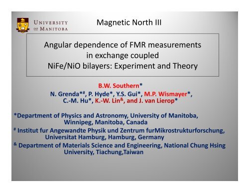
Magnetic North III<br />
<strong>Angular</strong> <strong>dependence</strong> <strong>of</strong> <strong>FMR</strong> <strong>measurements</strong><br />
<strong>in</strong> <strong>exchange</strong> coupled<br />
NiFe/NiO bilayers: Experiment and Theory<br />
B.W. Southern*<br />
N. Grenda* # , P. Hyde*, Y.S. Gui*, M.P. Wismayer*,<br />
C.‐M. Hu*, K.‐W. L<strong>in</strong> & , and J. van Lierop*<br />
*Department <strong>of</strong> Physics and Astronomy, University <strong>of</strong> Manitoba,<br />
W<strong>in</strong>nipeg, Manitoba, Canada<br />
#<br />
Institut fur Angewandte Physik und Zentrum furMikrostrukturforschung,<br />
Universitat Hamburg, Hamburg, Germany<br />
&<br />
Department <strong>of</strong> Materials Science and Eng<strong>in</strong>eer<strong>in</strong>g, National Chung Hs<strong>in</strong>g<br />
University, Tiachung,Taiwan<br />
1
Outl<strong>in</strong>e<br />
• Introduction<br />
• Experimental results<br />
• Theoretical Interpretation<br />
• Summary<br />
2
77 0 K<br />
• Ferro (F) and Anti‐ferro (AF)<br />
films <strong>in</strong> contact exhibit the<br />
phenomenon <strong>of</strong> <strong>exchange</strong>‐bias<br />
first observed by Meiklejohn<br />
and Bean (1956) <strong>in</strong> CoO<br />
• Usually characterized by a<br />
shifted hysteresis loop after<br />
field cool<strong>in</strong>g.<br />
• Attributed to a unidirectional<br />
anisotropy<br />
• Applications <strong>in</strong> <strong>in</strong>formation<br />
storage technologies and was<br />
first practical application <strong>of</strong> AF<br />
<strong>in</strong> sp<strong>in</strong> valves<br />
Cooled <strong>in</strong> 1T<br />
3
Easy (0 0) Hard(90 0 )<br />
H c =( h R ‐h L )/2<br />
H ex =(h R +h L )/2<br />
See review articles by<br />
• Nogues and Schuller JMMM 192,203(1999)<br />
• Berkowitz and Takano JMMM 200,552 (1999)<br />
• Stamps J. Phys. D. 33, 247 (2000)<br />
• Kiwi JMMM 234,584 (2001)<br />
4
• Different experimental techniques yield different<br />
values for the coupl<strong>in</strong>g field H ex at the <strong>in</strong>terface<br />
• Hysteresis loops <strong>in</strong>volve irreversible switch<strong>in</strong>g <strong>of</strong> the<br />
magnetization<br />
• <strong>FMR</strong> and BLS generally <strong>in</strong>volve small pertubations <strong>of</strong> the<br />
magnetization about equilibrium and are reversible<br />
• In this talk I will discuss a particular NiFe/NiO bilayer system<br />
where both magnetization and <strong>FMR</strong> <strong>measurements</strong> have<br />
been performed by research groups <strong>in</strong> Manitoba.<br />
5
Fabrication<br />
• The bilayer was prepared by the group <strong>of</strong><br />
Ko‐Wei L<strong>in</strong> at the National Chung Hs<strong>in</strong>g University <strong>in</strong><br />
Taiwan us<strong>in</strong>g a dual ion‐beam sputter<strong>in</strong>g technique<br />
at room temperature.<br />
L<strong>in</strong> et al Appl. Phys. Lett. 100, 122409(2012)<br />
• The NiFe/NiO film was fabricated on a SiO 2 substrate<br />
and no external field was applied dur<strong>in</strong>g any stage <strong>of</strong><br />
the growth<br />
epoxy<br />
SiO 2<br />
6
Analysis<br />
• NiO film layers had crystallite<br />
sizes between 5 and 20 nm <strong>in</strong><br />
diameter that penetrated the<br />
16 nm thickness (XRD)<br />
• ZFC and FC DC susceptibility<br />
<strong>measurements</strong> <strong>in</strong>dicated a<br />
block<strong>in</strong>g temperature T B =360K<br />
• NiO has a cubic fcc structure<br />
with alternat<strong>in</strong>g ferromagnetic<br />
sheets along the [111] direction<br />
• S<strong>in</strong>ce no field was applied<br />
dur<strong>in</strong>g fabrication, many AF<br />
doma<strong>in</strong> configurations could be<br />
present.(there 4 possible [111]<br />
directions as well as perhaps<br />
three <strong>in</strong> each plane)<br />
7
McCord: Adv <strong>in</strong> Solid State Physics 48, 157 (2009)<br />
• The presence <strong>of</strong> <strong>exchange</strong> bias and coercivity<br />
depends on the thickness <strong>of</strong> the AF layer<br />
• For 16 nm thickness, H c and H ex could be <strong>of</strong><br />
the same order <strong>of</strong> magnitude with H ex larger<br />
8
McCord: Adv <strong>in</strong> Solid State Physics 48, 157 (2009)<br />
Easy<br />
Hard<br />
9
Magnetometry<br />
• Magnetometry <strong>measurements</strong> by<br />
Van Lierop’s group on a sample<br />
<strong>of</strong> length 6 mm and width 2 mm<br />
for both a s<strong>in</strong>gle and bilayer were<br />
performed<br />
• Films were heated to 400K and<br />
cooled <strong>in</strong> a field <strong>of</strong> 2T<br />
• S<strong>in</strong>gle NiFe layer exhibited<br />
negligble coerciviity and no<br />
<strong>exchange</strong> bias<br />
• Bilayer sample exhibited both<br />
coercivity and <strong>exchange</strong> bias shift<br />
H ex ~ 2.0 mT along the cool<strong>in</strong>g field<br />
direction<br />
• H c ~ 1.1 mT @ 300K<br />
NiFe<br />
NiFe/NiO<br />
10
<strong>FMR</strong> Measurements<br />
• <strong>FMR</strong> <strong>measurements</strong> on the same<br />
samples were performed by the group<br />
<strong>of</strong> Can‐M<strong>in</strong>g Hu<br />
NiFe:<br />
L=21 mm W=20.0 mm T=9nm<br />
NiFe/NiO:<br />
L=16.3 mm W=13.8 mm T=9 nm<br />
• Broadband microwave absorption<br />
spectroscopy was used to detect<br />
the <strong>FMR</strong> frequency as evidenced<br />
by a transmission m<strong>in</strong>imum<br />
• A reference measurement at 150 mT<br />
is used to perform a subtraction<br />
at lower fields<br />
30mT<br />
150mT<br />
11
<strong>FMR</strong><br />
• External field is applied <strong>in</strong>‐plane at<br />
various angles φ with respect to the<br />
long direction<br />
• For each φ, a reference measurement<br />
is made at ± 150 mT and then either<br />
an up sweep or a down sweep is<br />
carried out between ±30 mT at<br />
<strong>in</strong>tervals <strong>of</strong> 0.4 mT<br />
• No heat<strong>in</strong>g or cool<strong>in</strong>g <strong>in</strong> a field performed<br />
• Two dist<strong>in</strong>ct types <strong>of</strong> behaviour are observed for the <strong>FMR</strong><br />
frequency as a function <strong>of</strong> the field which depend upon the<br />
direction <strong>of</strong> the field.<br />
12
• Irreversible switch<strong>in</strong>g is observed <strong>in</strong> the range ‐6mT < H < 6mT<br />
• For all angles < 45 0 a s<strong>in</strong>gle peak is found<br />
• Frequency range is 2.0 < f < 2.5 GHz<br />
13
• Irreversible switch<strong>in</strong>g is observed <strong>in</strong> the range ‐8mT < H < 8mT<br />
• For all angles >60 0 a two peaks are found<br />
• Suggests a two step reversal process<br />
• Frequency range is 2.7 < f < 3.4 GHz<br />
14
μ 0 M s =963 mT, γ= 176 GHz/T<br />
2<br />
0<br />
f <br />
r<br />
H Ms<br />
H<br />
15
Up sweep<br />
Down sweep<br />
• For 4.5 GHz we can plot the resonant field H r as a function <strong>of</strong> φ<br />
• Can be fit to the form H r = a 0 + a 1 cos(φ) + a 6 cos(6φ)<br />
a 0 = 25.306 mT, a 1 = .345 mT and a 6 =‐0.133 mT for up sweep (a)<br />
a 0 = 25.338 mT, a 1 = .296 mT and a 6 =‐0.237 mT for down sweep (b)<br />
• Suggests that there may be a unidirectional anisotropy as well as<br />
a six‐fold anisotropy<br />
16
? Theory<br />
17
• In order to model this behaviour we treat the NiFe as a s<strong>in</strong>gle<br />
doma<strong>in</strong> and <strong>in</strong>clude the effect <strong>of</strong> the NiO as <strong>in</strong>troduc<strong>in</strong>g<br />
anisotropies at the <strong>in</strong>terface<br />
• The energy <strong>of</strong> the system can be written as<br />
1 x x<br />
E H.<br />
M M S S S S S S S<br />
2 2 4<br />
x S S 15S S 15S S jS<br />
6<br />
<br />
2 2 2 4 2 2 2 2 2 2<br />
z x x y y z z x<br />
6 6 4 2 2 4<br />
x y x y x y x<br />
<br />
<br />
• Use spherical coord<strong>in</strong>ates to f<strong>in</strong>d extrema <strong>of</strong> E as function <strong>of</strong><br />
the field direction φ H and magnitude<br />
• Calculate <strong>FMR</strong> frequencies us<strong>in</strong>g Smit‐Beljers formula (1955)<br />
<br />
<br />
<br />
M<br />
s<br />
1<br />
s<strong>in</strong><br />
E E<br />
<br />
E<br />
2<br />
<br />
18
90 degrees x 2 =3 mT x 4 = ‐8mT x 6 = 0.1 mT<br />
19
0 degrees x 2 =3 mT x 4 = ‐8mT x 6 = 0.1 mT<br />
20
0 degrees 90 degrees<br />
21
45 60 80<br />
22
Downsweep<br />
90 degrees<br />
23
Downsweep<br />
0 degrees<br />
24
Summary<br />
• Bilayers were fabricated <strong>in</strong> zero field and no field cool<strong>in</strong>g was<br />
performed for the <strong>FMR</strong> <strong>measurements</strong><br />
• M<strong>in</strong>or hysteresis loops appear as the field direction is rotated<br />
from 0 to 90 degrees with respect to the longer sample side<br />
• The s<strong>in</strong>gle doma<strong>in</strong> model is too simple to make detailed<br />
comparisons with experiment but does <strong>in</strong>dicate that<br />
anisotropies contribute to the angular <strong>dependence</strong> <strong>of</strong> the<br />
resonant frequencies<br />
• F layer may not be homogeneous at <strong>in</strong>terface<br />
• Micromagnetic results <strong>in</strong>dicate that reversal is not s<strong>in</strong>gle doma<strong>in</strong><br />
• AF layer is treated as be<strong>in</strong>g static and provid<strong>in</strong>g an effective<br />
anisotropy<br />
• The micromagnetic calculations need to be extended to multiple<br />
layers which would allow some dynamics <strong>in</strong> the AF<br />
25
The End<br />
26


