Owner's Manual - Casablanca Fan
Owner's Manual - Casablanca Fan
Owner's Manual - Casablanca Fan

You also want an ePaper? Increase the reach of your titles
YUMPU automatically turns print PDFs into web optimized ePapers that Google loves.
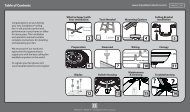
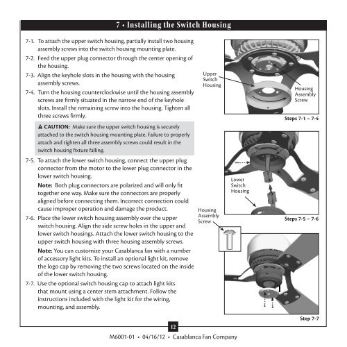
7 • Installing the Switch Housing<br />
7-1. To attach the upper switch housing, partially install two housing<br />
assembly screws into the switch housing mounting plate.<br />
7-2. Feed the upper plug connector through the center opening of<br />
the housing.<br />
7-3. Align the keyhole slots in the housing with the housing<br />
assembly screws.<br />
7-4. Turn the housing counterclockwise until the housing assembly<br />
screws are firmly situated in the narrow end of the keyhole<br />
slots. Install the remaining screw into the housing. Tighten all<br />
three screws firmly.<br />
CAUTION: Make sure the upper switch housing is securely<br />
attached to the switch housing mounting plate. Failure to properly<br />
attach and tighten all three assembly screws could result in the<br />
switch housing fixture falling.<br />
7-5. To attach the lower switch housing, connect the upper plug<br />
connector from the motor to the lower plug connector in the<br />
lower switch housing.<br />
Note: Both plug connectors are polarized and will only fit<br />
together one way. Make sure the connectors are properly<br />
aligned before connecting them. Incorrect connection could<br />
cause improper operation and damage the product.<br />
7-6. Place the lower switch housing assembly over the upper<br />
switch housing. Align the side screw holes in the upper and<br />
lower switch housings. Attach the lower switch housing to the<br />
upper switch housing with three housing assembly screws.<br />
Note: You can customize your <strong>Casablanca</strong> fan with a number<br />
of accessory light kits. To install an optional light kit, remove<br />
the logo cap by removing the two screws located on the inside<br />
of the lower switch housing.<br />
7-7. Use the optional switch housing cap to attach light kits<br />
that mount using a center stem attachment. Follow the<br />
instructions included with the light kit for the wiring,<br />
mounting, and assembly.<br />
Upper<br />
Switch<br />
Housing<br />
Housing<br />
Assembly<br />
Screw<br />
Lower<br />
Switch<br />
Housing<br />
Housing<br />
Assembly<br />
Screw<br />
Steps 7-1 – 7-4<br />
Steps 7-5 – 7-6<br />
12<br />
M6001-01 • 04/16/12 • <strong>Casablanca</strong> <strong>Fan</strong> Company<br />
Step 7-7