Owner's Manual - Casablanca Fan
Owner's Manual - Casablanca Fan
Owner's Manual - Casablanca Fan

Create successful ePaper yourself
Turn your PDF publications into a flip-book with our unique Google optimized e-Paper software.
Tribeca<br />
Owner’s Guide and Installation <strong>Manual</strong><br />
English<br />
Form# M6001-01<br />
20120416<br />
©2012 <strong>Casablanca</strong> <strong>Fan</strong> Co.
Welcome<br />
Your new <strong>Casablanca</strong>® ceiling fan is an addition to your home or<br />
office that will provide comfort and performance for many years. This<br />
installation and operation manual gives you complete instructions for<br />
installing and operating your fan.<br />
We are proud of our work. We appreciate the opportunity to supply<br />
you with the best ceiling fan available anywhere in the world.<br />
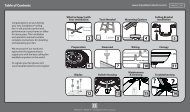
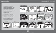
Table Of Contents<br />
Preparing the <strong>Fan</strong> Site .................3<br />
1 • Getting Ready ......................6<br />
2 • Installing the Ceiling Bracket. .......7<br />
3 • Assembling and Hanging the <strong>Fan</strong> ...8<br />
4 • Wiring Your Ceiling <strong>Fan</strong>. ............9<br />
5 • Installing the Canopy ...............10<br />
6 • Assembling the Blades. .............11<br />
7 • Installing the Switch Housing .......12<br />
8 • Operating and Cleaning Your Ceiling<br />
<strong>Fan</strong> ...............................13<br />
9 • Troubleshooting. ...................14<br />
Before installing your fan, for your records and warranty assistance,<br />
record information from the carton and <strong>Casablanca</strong> nameplate label<br />
(located on the top of the fan motor housing).<br />
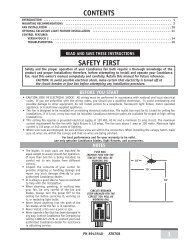
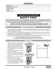
Cautions and Warnings<br />
• READ THIS ENTIRE MANUAL CAREFULLY BEFORE BEGINNING<br />
INSTALLATION. SAVE THESE INSTRUCTIONS.<br />
• Use only <strong>Casablanca</strong> replacement parts.<br />
• To reduce the risk of personal injury, attach the fan directly to the<br />
support structure of the building according to these instructions,<br />
and use only the hardware supplied.<br />
• To avoid possible electrical shock, before installing your fan,<br />
disconnect the power by turning off the circuit breakers to the<br />
outlet box and associated wall switch location. If you cannot lock<br />
the circuit breakers in the off position, securely fasten a prominent<br />
warning device, such as a tag, to the service panel.<br />
• All wiring must be in accordance with national and local electrical<br />
codes and ANSI/NFPA 70. If you are unfamiliar with wiring, use a<br />
qualified electrician.<br />
• To reduce the risk of personal injury, do not bend the blade<br />
attachment system when installing, balancing, or cleaning the fan.<br />
Never insert foreign objects between rotating fan blades.<br />
• To reduce the risk of fire, electrical shock, or motor damage, do not<br />
use a solid-state speed control with this fan. Use only <strong>Casablanca</strong><br />
speed controls.<br />
• This product conforms to UL STD 507 and is certified to STD C22.2<br />
No. 113.<br />
• Wash your hands after your fan installation is complete.<br />
© 2012 <strong>Casablanca</strong> <strong>Fan</strong> Company<br />
2<br />
M6001-01 • 04/16/12 • <strong>Casablanca</strong> <strong>Fan</strong> Company
Preparing the <strong>Fan</strong> Site<br />
Step 1 - Choose the <strong>Fan</strong> Site<br />
Proper ceiling fan location and attachment to the building<br />
structure are essential for safety, reliable operation, maximum<br />
efficiency, and energy savings.<br />
Choose a fan site where:<br />
• No object can come in contact with the rotating fan blades during<br />
normal operation.<br />
• The fan blades are at least 7 feet above the floor and the ceiling is<br />
at least 9 feet high.<br />
30” From<br />
Wall or<br />
Nearest<br />
Obstruction<br />
7’ Minimum<br />
Blades to<br />
Floor<br />
9’ Minimum<br />
Ceiling<br />
Height<br />
• The fan blades have no obstructions to airflow, such as walls or<br />
posts, within 30 inches of the fan blade tips.<br />
• The fan is directly below a joist or support brace that will hold the<br />
outlet box and the full weight of the fan.<br />
Checklist for Existing <strong>Fan</strong> Site<br />
If you want to use an existing fan site, complete the following checklist to<br />
determine if the site is acceptable and safe for your new <strong>Casablanca</strong> fan.<br />
If you cannot check off every item, prepare a new fan site as described on<br />
this page.<br />
<strong>Fan</strong> Support System<br />
• <strong>Fan</strong> attaches directly to building structure.<br />
• <strong>Fan</strong> support system will hold full weight of the fan and light kit.<br />
Ceiling Hole<br />
• The outlet box clearance hole is directly below the joist or support brace.<br />
Outlet Box<br />
• The outlet box is an UL-approved octagonal 4” x 1-1/2” outlet box (or as<br />
specified by the support brace manufacturer).<br />
• The outlet box is secured to the joist or support brace by wood screws<br />
and washers through the inner holes of outlet box.<br />
• The outer holes of the outlet box are aligned with joist or support brace.<br />
• The bottom of the outlet box is recessed a minimum of 1/16” into<br />
ceiling.<br />
Wiring<br />
• The electrical cable is secured to outlet box by an approved connector.<br />
• Six inches of lead wires extend from outlet box.<br />
If your existing fan site is suitable, skip ahead to Section 2 • Installing the<br />
Ceiling Bracket.<br />
<strong>Fan</strong> Support<br />
System<br />
<strong>Fan</strong> Support<br />
System<br />
Suitable Existing <strong>Fan</strong> Site<br />
Wiring<br />
Outlet Box<br />
3<br />
M6001-01 • 04/16/12 • <strong>Casablanca</strong> <strong>Fan</strong> Company
Preparing the <strong>Fan</strong> Site (continued)<br />
Step 2 - Cut the Ceiling Hole<br />
2-1. Locate the site for the ceiling hole directly below the joist or support brace that<br />
will hold the outlet box and fan.<br />
2-2. Cut a 4” diameter hole through the drywall or plaster of the ceiling. You will use<br />
the hole to install the support brace and outlet box.<br />
Step 3 - Install a Support Brace, If Necessary<br />
Determine if there is a ceiling joist directly above the ceiling hole. If the joist is there,<br />
determine if it is positioned to allow you to recess the outlet box a minimum of<br />
1/16” into the ceiling. If NOT, install a support brace as follows:<br />
3-1. Attach a 2” x 4” support brace between two joists. Position it to allow you to<br />
recess the bottom of the outlet box a minimum of 1/16” into the ceiling.<br />
3-2. Check the support brace to ensure it will support the full weight of the fan and<br />
light kit.<br />
Step 4 - Install the Outlet Box<br />
4-1. Obtain a UL-approved octagonal 4” x 1-1/2” outlet box, plus two #8 x 1-1/2”<br />
wood screws and washers, available from any hardware store or electrical supply<br />
house.<br />
4-2. Orient the outlet box so that both the inner and outer holes in the box align<br />
with the joist or support brace.<br />
4-3. Drill pilot holes no larger than the minor diameter of the wood screws (5/64”)<br />
through the inner holes of the outlet box.<br />
4-4. Attach the outlet box directly to the support brace or joist with two #8 x 1-1/2”<br />
wood screws and washers. Th e bottom of the outlet box must be recessed a<br />
minimum of 1/16” into the ceiling.<br />
Step 5 - Prepare the Wiring<br />
5-1. Make sure the circuit breakers to the fan supply line leads and associated wall<br />
switch location are turned off . If you cannot lock the circuit breakers in the<br />
off position, securely fasten a prominent warning device, such as a tag, to the<br />
service panel.<br />
5-2. Thread the fan supply line through the outlet box so that the fan supply line<br />
extends at least 6” beyond the box.<br />
5-3. Attach the fan supply line to the outlet box with an approved connector,<br />
available at any hardware store or electrical supply house.<br />
5-4. Make certain the wiring meets all national and local standards and ANSI/NFPA 70.<br />
You have now successfully prepared your ceiling fan site. For instructions to install<br />
your ceiling fan, go to your fan manual and continue with Section 2 • Installing the<br />
Ceiling Bracket.<br />
4<br />
M6001-01 • 04/16/12 • <strong>Casablanca</strong> <strong>Fan</strong> Company<br />
Steps 2 – 3<br />
Step 4<br />
Step 5<br />
CAUTION: All wiring must be in<br />
accordance with national and local<br />
electrical codes and ANSI/NFPA 70. If<br />
you are unfamiliar with wiring, use a<br />
qualified electrician.
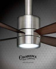
Installer’s Choice and Optional Accessories<br />
Standard<br />
Mounting<br />
Style<br />
Support Brace<br />
Ceiling<br />
Outlet Box<br />
Standard Mounting hangs from the<br />
ceiling by a downrod (included).<br />
Understanding Mounting and Installer’s Choice<br />
<strong>Casablanca</strong>’s 2-position mounting system provides you maximum<br />
installation flexibility and ease. You can install your fan in one<br />
of two ways, depending on ceiling height and your preference:<br />
standard or angled mounting. The steps in this manual include<br />
instructions for both mounting methods.<br />
Considering Optional Accessories<br />
Consider using Hunter’s optional accessories, including a<br />
wall-mounted or remote speed control. To install and use the<br />
accessories, follow the instructions included with each product.<br />
For quiet and optimum performance of your Hunter fan, use only<br />
Hunter speed controls.<br />
Support Brace<br />
For ceilings higher than 9 feet, you can purchase <strong>Casablanca</strong><br />
extension downrods. All <strong>Casablanca</strong> fans use sturdy 3/4” diameter<br />
pipe to assure stability and wobble-free performance.<br />
Angled<br />
Mounting<br />
Style<br />
Ceiling<br />
Outlet Box<br />
12<br />
8<br />
CAUTION: To reduce the risk of personal injury, attach the<br />
fan directly to the support structure of the building according<br />
to these instructions, and use only the hardware supplied.<br />
Angled Mounting recommended for a<br />
vaulted or angled ceiling.<br />
5<br />
M6001-01 • 04/16/12 • <strong>Casablanca</strong> <strong>Fan</strong> Company
To install a ceiling fan, be sure you can do the following:<br />
• Locate the ceiling joist or other suitable support in ceiling.<br />
• Drill holes for and install wood screws.<br />
• Identify and connect electrical wires.<br />
• Lift 40 pounds.<br />
If you need help installing the fan, your <strong>Casablanca</strong> fan dealer can<br />
direct you to a licensed installer or electrician.<br />
Gathering the Tools<br />
You will need the following tools for installing the fan:<br />
• Electric drill with 9/64” bit<br />
• Standard screwdriver (magnetic tip recommended)<br />
• Phillips-head screwdriver (magnetic tip recommended)<br />
• Wrench or pliers<br />
• Ladder (height dependent upon installation site)<br />
1 • Getting Ready<br />
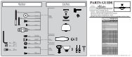
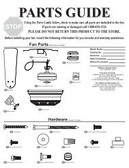
Checking Your <strong>Fan</strong> Parts<br />
Carefully unpack your fan to avoid damage to the fan parts. Refer<br />
to the included Parts Guide. Check for any shipping damage to the<br />
motor or fan blades. If any parts are missing or damaged, contact your<br />
<strong>Casablanca</strong> dealer or call <strong>Casablanca</strong> Technical Support Department at<br />
888-227-2178 (In Canada, call 1-866-268-1936).<br />
Installing Multiple <strong>Fan</strong>s?<br />
If you are installing more than<br />
one fan, keep the fan blades and<br />
blade irons (if applicable) in sets,<br />
as they were shipped.<br />
Preparing the <strong>Fan</strong> Site<br />
Before you begin installing the fan, follow all the instructions in<br />
“Preparing the <strong>Fan</strong> Site.” Proper ceiling fan location and attachment<br />
to the building structure are essential for safety, reliable operation,<br />
maximum efficiency, and energy savings.<br />
WARNING! To avoid possible electrical shock, make certain<br />
that electricity is turned off at the circuit breaker or fuse box<br />
before attempting any installation or repair procedure.<br />
6<br />
M6001-01 • 04/16/12 • <strong>Casablanca</strong> <strong>Fan</strong> Company
2 • Installing the Ceiling Bracket<br />
CAUTION: To avoid possible electrical shock, before installing your fan,<br />
disconnect the power by turning off the circuit breakers to the outlet box<br />
and associated wall switch location. If you cannot lock the circuit breakers<br />
in the off position, securely fasten a prominent warning device, such as a<br />
tag, to the service panel.<br />
Isolator<br />
Ceiling<br />
Bracket<br />
2-1. Note: The ceiling bracket may be mounted to an existing ceiling-<br />
-fan-rated outlet box. If the outlet box is not ceiling-fan-rated,<br />
Drill two pilot holes into the wood support structure.<br />
The pilot holes should be 9/64” in diameter and through the<br />
outermost holes in the outlet box.<br />
2-2. Your fan comes with four neoprene noise isolators. Position the<br />
isolators between the ceiling bracket and the ceiling by inserting<br />
the raised areas on each isolator into the holes in the ceiling<br />
bracket.<br />
2-3. Align the slotted holes in the ceiling bracket with the pilot holes<br />
you drilled in the wood support structure. Note: The isolators<br />
should be flush against the ceiling.<br />
2-4. Place a flat washer on each of the two 3” wood screws and pass<br />
the screws through the slotted holes in the ceiling bracket into the<br />
pilot holes you drilled.<br />
Tighten the screws into the 9/64” pilot holes; do not use lubricants<br />
on the screws. Do not over tighten.<br />
Step 2-2<br />
Steps 2-3 – 2-5<br />
Flat Washer<br />
3” Wood<br />
Screw<br />
7<br />
M6001-01 • 04/16/12 • <strong>Casablanca</strong> <strong>Fan</strong> Company
3 • Assembling and Hanging the <strong>Fan</strong><br />
WARNING: <strong>Fan</strong> may fall if not assembled as directed in these<br />
installation instructions.<br />
You can assemble your fan for standard or angled mounting as<br />
shown in steps below.<br />
3-1. Unbundle the wires from the fan.<br />
3-2. Feed the wires from the fan through the downrod.<br />
Note: Make sure all the wires are on the same side of the metal<br />
dowel pin inside the downrod.<br />
3-3. Loosen the square head setscrew on the adapter in order to<br />
install the downrod.<br />
3-4. Insert the downrod into the adapter. Tighten by turning the<br />
downrod assembly at least 4-5 full turns until it stops. Note:<br />
When the downrod assembly is fully installed, 2-3 threads<br />
on the pipe will still be visible; this is normal. Securely<br />
retighten the setscrew with a wrench or pliers.<br />
WARNING: If the setscrew is not tightened securely, the fan<br />
may fall.<br />
Steps 3-1 – 3-4<br />
Setscrew<br />
Downrod<br />
Canopy<br />
Adapter<br />
3-5. (Optional) - The wires can be cut (shortened), but leave at<br />
least 8” extending from the top of the downrod.<br />
3-6. Raise the fan and place the downrod ball into the ceiling bracket.<br />
For angled ceilings, point<br />
opening toward peak<br />
Step 3-6<br />
Ceiling<br />
Bracket<br />
Downrod<br />
Ball<br />
8<br />
M6001-01 • 04/16/12 • <strong>Casablanca</strong> <strong>Fan</strong> Company
4 • Wiring Your Ceiling <strong>Fan</strong><br />
All wiring must be in accordance with national and local electrical<br />
codes and ANSI/NFPA 70. If you are unfamiliar with wiring, use a<br />
qualified electrician.<br />
4-1. Make sure the power is still off at the breaker box.<br />
4-2. To connect the wires, hold the bare metal leads together and place a<br />
wire connector over them, then twist clockwise until tight. For all wire<br />
connections use the wire connector provided.<br />
CAUTION: Be sure no bare wire or wire strands are visible after<br />
making connections.<br />
Note: For dual switch wiring, skip steps 4-3 through 4-6. Continue on<br />
next page; performing steps 4-7 through 4-11.<br />
FROM FAN<br />
FROM CEILING<br />
green wire<br />
with yellow<br />
stripe<br />
green wire<br />
with yellow<br />
stripe<br />
green or bare<br />
(grounding)<br />
Single Switch Wiring:<br />
4-3. Connect the green or bare wire (grounding) wire from the ceiling<br />
to the green wire with yellow stripe (grounding) from the ceiling<br />
bracket and to the green wire with yellow stripe (grounding) from<br />
the fan.<br />
4-4. Connect the white wire (grounded) from the ceiling to the white wire<br />
from the fan.<br />
4-5. Connect the black wire (ungrounded) from the ceiling to the black<br />
wire and the blue wire from the fan.<br />
Step 4-3 and 5-3<br />
FROM CEILING BRACKET<br />
FROM CEILING<br />
4-6. After all connections are made, turn wire connectors upward and<br />
push them up into the outlet box. Be sure to separate the grounded<br />
wires from the ungrounded wires inside the outlet box.<br />
white (grounded)<br />
white<br />
blue<br />
black (ungrounded) black<br />
Wire<br />
Connector<br />
F RO M FA N<br />
9<br />
M6001-01 • 04/16/12 • <strong>Casablanca</strong> <strong>Fan</strong> Company<br />
Steps 4-4 -4-5
4 • Wiring Your Ceiling <strong>Fan</strong> (continued)<br />
CAUTION: Be sure no bare wire or wire strands are visible after<br />
making connections.<br />
FROM CEILING<br />
Dual Switch Wiring:<br />
4-7. Connect the green or bare wire (grounding) from the ceiling to the<br />
green wire with yellow stripe (grounding) from the ceiling bracket<br />
to the green wire with yellow stripe (grounding) from the fan. See<br />
image on previous page.<br />
4-8. Connect the white wire (grounded) from the ceiling to the white wire<br />
from the fan.<br />
4-9. Connect the black wire (ungrounded) from the ceiling to the black<br />
wire from the fan.<br />
white (grounded)<br />
white<br />
black/white<br />
(ungrounded)<br />
blue<br />
black<br />
(ungrounded)<br />
black<br />
4-10. Connect the blue wire from the fan to the black wire with white<br />
stripe (ungrounded) from the wall switch.<br />
4-11. After all connections are made, turn wire connectors upward and<br />
push them up into the outlet box. Be sure to separate the grounded<br />
wires from the ungrounded wires inside the outlet box.<br />
5 • Installing the Canopy<br />
Steps 4-8 - 4-10<br />
F RO M FA N<br />
5-1. Raise the canopy over the ceiling bracket and<br />
align the two holes of the canopy and the<br />
ceiling bracket.<br />
5-2. Insert and tighten the canopy screws securely.<br />
Hanger<br />
Bracket<br />
Canopy Screw<br />
Canopy<br />
Screw<br />
Canopy<br />
Step 5-1<br />
10<br />
Steps 5-2<br />
M6001-01 • 04/16/12 • <strong>Casablanca</strong> <strong>Fan</strong> Company
6 • Assembling the Blades<br />
6-1. Using the provided Allen wrench, attach each blade to the<br />
blade iron using three barrel nuts and three decorative<br />
screws as shown.<br />
Note: You may place the decorative screws and barrel nuts<br />
facing up or down.<br />
6-2. Remove the two orange shipping rings from motor by lifting<br />
up on the edge of the rings.<br />
6-3. Align the five holes in the blade iron ring and the decorative<br />
ring with the five holes in the bottom of the motor and<br />
partially install the five blade mounting screws.<br />
6-4. Once all five of the screws are partially installed, tighten<br />
them securely.<br />
Allen Wrench<br />
Step 6-1<br />
Blade Iron<br />
Barrel Nut<br />
Decorative<br />
Screw<br />
Blade Iron<br />
Ring<br />
Decorative<br />
Ring<br />
Shipping<br />
Ring<br />
Blade<br />
Mounting<br />
Screw<br />
Step 6-2<br />
Steps 6-3 - 6-4<br />
11<br />
M6001-01 • 04/16/12 • <strong>Casablanca</strong> <strong>Fan</strong> Company
7 • Installing the Switch Housing<br />
7-1. To attach the upper switch housing, partially install two housing<br />
assembly screws into the switch housing mounting plate.<br />
7-2. Feed the upper plug connector through the center opening of<br />
the housing.<br />
7-3. Align the keyhole slots in the housing with the housing<br />
assembly screws.<br />
7-4. Turn the housing counterclockwise until the housing assembly<br />
screws are firmly situated in the narrow end of the keyhole<br />
slots. Install the remaining screw into the housing. Tighten all<br />
three screws firmly.<br />
CAUTION: Make sure the upper switch housing is securely<br />
attached to the switch housing mounting plate. Failure to properly<br />
attach and tighten all three assembly screws could result in the<br />
switch housing fixture falling.<br />
7-5. To attach the lower switch housing, connect the upper plug<br />
connector from the motor to the lower plug connector in the<br />
lower switch housing.<br />
Note: Both plug connectors are polarized and will only fit<br />
together one way. Make sure the connectors are properly<br />
aligned before connecting them. Incorrect connection could<br />
cause improper operation and damage the product.<br />
7-6. Place the lower switch housing assembly over the upper<br />
switch housing. Align the side screw holes in the upper and<br />
lower switch housings. Attach the lower switch housing to the<br />
upper switch housing with three housing assembly screws.<br />
Note: You can customize your <strong>Casablanca</strong> fan with a number<br />
of accessory light kits. To install an optional light kit, remove<br />
the logo cap by removing the two screws located on the inside<br />
of the lower switch housing.<br />
7-7. Use the optional switch housing cap to attach light kits<br />
that mount using a center stem attachment. Follow the<br />
instructions included with the light kit for the wiring,<br />
mounting, and assembly.<br />
Upper<br />
Switch<br />
Housing<br />
Housing<br />
Assembly<br />
Screw<br />
Lower<br />
Switch<br />
Housing<br />
Housing<br />
Assembly<br />
Screw<br />
Steps 7-1 – 7-4<br />
Steps 7-5 – 7-6<br />
12<br />
M6001-01 • 04/16/12 • <strong>Casablanca</strong> <strong>Fan</strong> Company<br />
Step 7-7
8 • Operating and Cleaning Your Ceiling <strong>Fan</strong><br />
8-1. Turn on electrical power to the fan.<br />
8-2. The fan pull chain controls power to the fan. The pull chain has<br />
five settings in sequence: High, Medium, Low, Extra Low and Off.<br />
• Pull the chain slowly to change settings.<br />
• Release slowly to prevent the chain from recoiling into the blades.<br />
• The chain uses a breakaway connector that separates if the<br />
chain is jerked. If this happens, simply reinsert the chain into<br />
the connector.<br />
8-3. The light pull chain controls the power to the light fixture. The<br />
chain has two settings: ON and OFF.<br />
8-4. Ceiling fans work best by blowing air downward (counterclockwise<br />
blade rotation) in warm weather to cool the room with a direct<br />
breeze. In winter, having the fan draw air upward (clockwise blade<br />
rotation) will distribute the warmer air trapped at the ceiling<br />
around the room without causing a draft.<br />
8-5. For cleaning finishes, use a soft brush or lint-free cloth to prevent<br />
scratching. A vacuum cleaner brush nozzle can remove heavier<br />
dust. Remove surface smudges or accumulated dirt and dust using<br />
a mild detergent and a slightly dampened cloth. You may use<br />
an artistic agent, but never abrasive cleaning agents as they will<br />
damage the finish.<br />
8-6. Clean wood finish blades with a furniture polishing cloth.<br />
Occasionally, apply a light coat of furniture polish for added<br />
protection and beauty. Clean painted and high-gloss blades in the<br />
same manner as the fan finish.<br />
In warm weather, use<br />
downward air flow pattern<br />
In cold weather, use upward<br />
air flow pattern<br />
To Change Airflow Direction<br />
Turn the fan off and let it come to a complete<br />
stop. Slide the reversing switch on the fan to the<br />
opposite position. Restart fan.<br />
Reversing<br />
Switch<br />
13<br />
M6001-01 • 04/16/12 • <strong>Casablanca</strong> <strong>Fan</strong> Company
9 • Troubleshooting<br />
Problem: Nothing happens; fan does not move.<br />
1. Turn power on, replace fuse, or reset breaker.<br />
2. Loosen canopy, check all connections according to the wiring the<br />
fan section.<br />
3. Remove the shipping bumpers.<br />
4. Make sure the wall control is paired. (See Pairing the Wall Control<br />
on page 14.)<br />
Problem: Noisy operation.<br />
1. Tighten the blade assembly screws and blade iron armature screws<br />
until snug.<br />
2. Check to see if the blade is cracked. If so, replace all the blades.<br />
Problem: Excessive wobbling.<br />
1. If your fan wobbles when operating, use the enclosed balancing kit<br />
and instructions to balance the fan.<br />
2. Tighten all blade iron screws.<br />
3. Turn power off, support fan very carefully, and check that the<br />
hanger ball is properly seated.<br />
If you need parts or service assistance, please call<br />
888‐830‐1326 (In Canada, call 1-888-227-2178) or<br />
visit us at our website at<br />
http://www.<strong>Casablanca</strong><strong>Fan</strong>Co.com.<br />
<strong>Casablanca</strong> <strong>Fan</strong> Company<br />
7130 Goodlett Farms Pkwy. #400<br />
Memphis, Tennessee 38016<br />
AUTHORIZED SERVICE CENTERS<br />
For the most updated listing of <strong>Casablanca</strong> Authorized Service Centers,<br />
visit www.<strong>Casablanca</strong><strong>Fan</strong>Co.com/servicecenters or call toll free 1-888-227-2178.<br />
14<br />
M6001-01 • 04/16/12 • <strong>Casablanca</strong> <strong>Fan</strong> Company