Digital Current Control of a Voltage Source Converter With Active ...
Digital Current Control of a Voltage Source Converter With Active ...
Digital Current Control of a Voltage Source Converter With Active ...

Create successful ePaper yourself
Turn your PDF publications into a flip-book with our unique Google optimized e-Paper software.
WU AND LEHN: DIGITAL CURRENT CONTROL OF A VOLTAGE SOURCE CONVERTER 1365<br />
at relatively low switching frequencies. This new system allows<br />
for the flexible, systematic design approach <strong>of</strong> pole assignment<br />
while retaining control <strong>of</strong> the current trajectory, providing transient<br />
overcurrent protection even when the controller’s overall<br />
performance criteria cannot be met [9].<br />
II. SYSTEM MODELING<br />
Assuming that the impedances <strong>of</strong> the three-phase system <strong>of</strong><br />
Fig. 1 are balanced, the differential equations governing the<br />
three-phase voltage and current vectors are<br />
The three-phase vectors , , , , and<br />
in (1)–(3) can be replaced by complex space vectors , ,<br />
, , and in the form by applying<br />
the amplitude-invariant Clarke transformation<br />
(1)<br />
(2)<br />
(3)<br />
(4)<br />
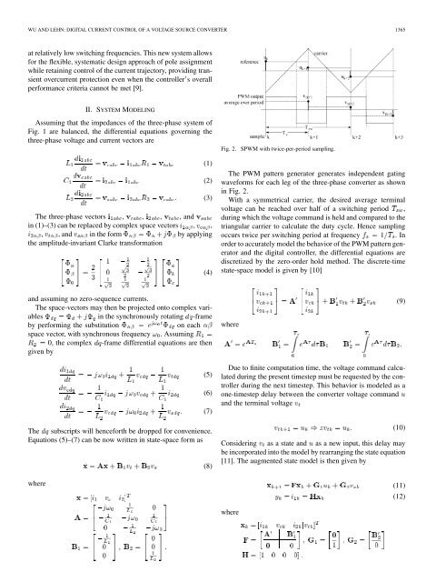
Fig. 2. SPWM with twice-per-period sampling.<br />
The PWM pattern generator generates independent gating<br />
waveforms for each leg <strong>of</strong> the three-phase converter as shown<br />
in Fig. 2.<br />
<strong>With</strong> a symmetrical carrier, the desired average terminal<br />
voltage can be reached over half <strong>of</strong> a switching period ,<br />
during which the voltage command is held and compared to the<br />
triangular carrier to calculate the duty cycle. Hence sampling<br />
occurs twice per switching period at frequency 1 .In<br />
order to accurately model the behavior <strong>of</strong> the PWM pattern generator<br />
and the digital controller, the differential equations are<br />
discretized by the zero-order hold method. The discrete-time<br />
state-space model is given by [10]<br />
and assuming no zero-sequence currents.<br />
The space-vectors may then be projected onto complex variables<br />
in the synchronously rotating -frame<br />
by performing the substitution<br />
on each<br />
space vector, with synchronous frequency . Assuming<br />
0, the complex -frame differential equations are then<br />
given by<br />
where<br />
(9)<br />
(5)<br />
(6)<br />
(7)<br />
The subscripts will henceforth be dropped for convenience.<br />
Equations (5)–(7) can be now written in state-space form as<br />
(8)<br />
where<br />
Due to finite computation time, the voltage command calculated<br />
during the present timestep must be requested by the controller<br />
during the next timestep. This behavior is modeled as a<br />
one-timestep delay between the converter voltage command<br />
and the terminal voltage<br />
(10)<br />
Considering as a state and as a new input, this delay may<br />
be incorporated into the model by rearranging the state equation<br />
[11]. The augmented state model is then given by<br />
(11)<br />
(12)<br />
where