Digital Current Control of a Voltage Source Converter With Active ...
Digital Current Control of a Voltage Source Converter With Active ...
Digital Current Control of a Voltage Source Converter With Active ...

You also want an ePaper? Increase the reach of your titles
YUMPU automatically turns print PDFs into web optimized ePapers that Google loves.
WU AND LEHN: DIGITAL CURRENT CONTROL OF A VOLTAGE SOURCE CONVERTER 1371<br />
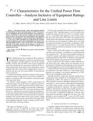
Fig. 15. d- and q-axis currents during a 10-A step in I , damping and integrator<br />
loops enabled.<br />
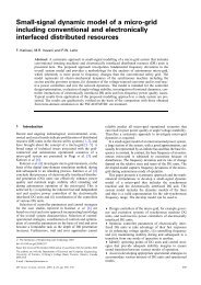
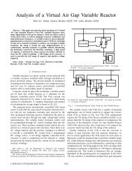
Fig. 17. d- and q-axis currents, and three-phase bus voltages during three-phase<br />
fault.<br />
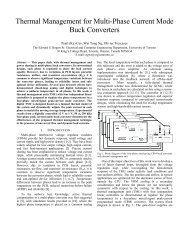
Fig. 16. Oscilloscope phase A signals during a 10-A step in I , damping and<br />
integrator loops enabled. Time: 5 ms/div. Top to bottom: i (20 A/div), v<br />
(100 V/div), i (20 A/div), v (100 V/div).<br />
Fig. 18. Oscilloscope screen capture <strong>of</strong> phase A signals during three-phase<br />
fault. Time: 5 ms/div. Top to bottom: i (10 A/div), v (100 V/div), i<br />
(10 A/div), v (100 V/div).<br />
shows that the step response is fast, the system is well-damped,<br />
and there is no ringing.<br />
B. Disturbance Rejection<br />
In order to demonstrate the ability <strong>of</strong> the controller to reject<br />
disturbances and its ability to damp the resonance from excitation<br />
by external sources, a balanced three-phase fault was introduced<br />
which instantaneously reduced the magnitude <strong>of</strong><br />
by approximately 2/3 for 15 ms before being cleared. The response<br />
<strong>of</strong> the system to this fault is shown in Figs. 17 and 18.<br />
There is a brief transient in due to the speed <strong>of</strong> the fault exceeding<br />
the controller bandwidth, and because <strong>of</strong> the approximation<br />
in the calculation <strong>of</strong> the feedforward gain.<br />
Otherwise, the system is well-damped despite the high speed<br />
and severity <strong>of</strong> the fault, as shown in the oscilloscope screen capture<br />
<strong>of</strong> Fig. 18. Despite imbalances caused by different clearing<br />
times for each phase, the controller maintains good regulation,<br />
demonstrating its ability to operate in an unbalanced system.<br />
C. Overcurrent Protection<br />
The current controller regulated the current during the fault<br />
so effectively that overcurrent limits were rarely reached. As<br />
a result, this controller could not be used to test the overcurrent<br />
protection. However, use <strong>of</strong> a less aggressive controller or<br />
a larger filter capacitor will make overcurrent limiting imperative.<br />
Fig. 19 shows the sampled and calculated - and -axis currents<br />
for a less aggressive damping controller during the fault,<br />
with the current limits set to 30 A in each axis. It can be seen<br />
that this controller allows high current levels to occur for a significant<br />
period <strong>of</strong> time. Despite the change in overall gain, the<br />
deadbeat controller maintained the same performance, tracking<br />
its reference with a fixed delay. Fig. 20 shows the corresponding<br />
phase A currents and voltages.<br />
The overcurrent limit was then set to 10 A in each axis and the<br />
balanced, three-phase fault was reintroduced to demonstrate the<br />
transient overcurrent protection capabilities <strong>of</strong> the controller. As<br />
shown in Fig. 21 the -axis current reaches the new overcurrent<br />
limit immediately after the fault but is clipped to 10 A. Ringing<br />
can be seen in the oscilloscope traces <strong>of</strong> and <strong>of</strong> Fig. 22<br />
following the fault. This occurs when the current is clipped because<br />
the sum <strong>of</strong> the damping and integral feedback is saturated,<br />
thus only the deadbeat controller is in operation with the current<br />
limit as its reference. <strong>With</strong> the damping feedback disabled<br />
by saturation, the fault excites ringing in the LC tank formed