Digital Current Control of a Voltage Source Converter With Active ...
Digital Current Control of a Voltage Source Converter With Active ...
Digital Current Control of a Voltage Source Converter With Active ...

Create successful ePaper yourself
Turn your PDF publications into a flip-book with our unique Google optimized e-Paper software.
WU AND LEHN: DIGITAL CURRENT CONTROL OF A VOLTAGE SOURCE CONVERTER 1367<br />
where<br />
Simple pole assignment may be used to determine the input<br />
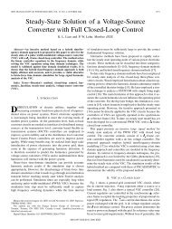
Fig. 5. Separation <strong>of</strong> a complex system into d- and q-axis components.<br />
(24)<br />
so that the closed-loop system has the desired state response.<br />
The actual gains and may then be found using (20) and<br />
(21), respectively.<br />
C. Optimal Pole Assignment<br />
In this study, linear quadratic (LQ) optimal control [10] is<br />
used to determine the gains and , since optimal control<br />
frees the designer from the mathematical abstraction <strong>of</strong> pole<br />
assignment. Furthermore, LQ controllers <strong>of</strong>fer good stability<br />
margins and robustness. Analyses <strong>of</strong> stability margins for discrete-time<br />
LQ regulators are given in [12] and [13].<br />
The LQ regulator is designed by solving the algebraic Riccati<br />
equation to determine a gain which minimizes the quadratic<br />
cost function<br />
(25)<br />
and determine the quadratic cost weightings on the state<br />
values and inputs, respectively. The th diagonal element <strong>of</strong><br />
determines the direct weighting on the th state, while <strong>of</strong>f-diagonal<br />
elements have more complicated effects and are set to zero<br />
in this study.<br />
Some empirical guidelines for their selection can be given.<br />
• Heavy weighting should be placed on to ensure fast,<br />
well-damped transient current response.<br />
• The impedance <strong>of</strong> the capacitor is fairly high and little current<br />
is shunted through ; thus and will behave similarly,<br />
and an equal cost should also be placed on .<br />
• should be allowed to move as dictated by the grid in<br />
order to avoid converter saturation. Low or zero weighting<br />
may be placed on this state.<br />
• Weighting on should initially be close to or at zero.<br />
While an increase in this weighting will limit the amount<br />
<strong>of</strong> control effort used, it will also decrease damping and<br />
stability. For the same reason, input weighting should<br />
initially be set to one.<br />
• A fairly high weighting should be placed on the integrator<br />
state , in order to attain high bandwidth. However, this<br />
increase comes at the expense <strong>of</strong> stability.<br />
The transient response <strong>of</strong> the converter terminal voltage<br />
should be verified during a 1 per-unit step in , to ensure that<br />
it lies within the available converter terminal voltage, including<br />
the voltage required to reject the bus voltage . may be<br />
limited by increasing either the weighting on or the input<br />
weighting .<br />
D. Separation <strong>of</strong> and Axes<br />
To implement and simulate the system, the controller and<br />
model must be decomposed into real-valued d and -axis systems.<br />
The result <strong>of</strong> a multiplication between vector and<br />
matrix can be separated into and components using the<br />
matrix equation<br />
(26)<br />
This process is shown graphically in Fig. 5. Equation (26) can<br />
be applied to every gain in Fig. 3 to find real-valued, coupled<br />
- and -axis controllers, and to the matrices <strong>of</strong> the closed-loop<br />
state model for simulation and numerical analysis.<br />
IV. SIMULATION RESULTS<br />
To verify the controller’s performance, an LCL-filter was designed<br />
following the guidelines presented in [14]. The sampling<br />
and switching frequencies were 8 kHz and 4 kHz, respectively,<br />
and the filter parameters were 1.0 mH 0.04 p.u.),<br />
0.5 mH 0.02 p.u. , 14 F 20 p.u. ,<br />
with a resonant frequency <strong>of</strong> 2.3 kHz. The 60 Hz, 1.4 kVA test<br />
system had a rated voltage <strong>of</strong> 115 V (line–line rms).<br />
Following the guidelines <strong>of</strong> Section III-C, the following LQ<br />
weightings were chosen:<br />
The per-unitization <strong>of</strong> and with base voltage 115 V<br />
and current 7 A can be done by writing and in terms<br />
<strong>of</strong> their per-unit values and<br />
(27)<br />
(28)