
Create successful ePaper yourself
Turn your PDF publications into a flip-book with our unique Google optimized e-Paper software.
Ya Hsin Industrial Co., Ltd.<br />
<strong>Service</strong> <strong>Manual</strong><br />
Model Name: LT32C1M1<br />
Revision: 1.00<br />
Date: 16-Apr.-2006<br />
32" Color TFT LCD Television (NTSC)
1.0 Product Description<br />
1.1 Introduction<br />
1.2 Features<br />
1.3 General Information<br />
1.4 Outline Dimension<br />
2.0 Engineering Specifications<br />
2.1 TFT LCD Panel Specifications:<br />
2.2 Optical Characteristics<br />
2.3 I/O Connectors<br />
2.4 D-Sub (Analog) Input<br />
2.5 PC Audio Input (line-in)<br />
2.6 ISP (In System Programming)<br />
2.7 Analog Compliant Timings<br />
2.8 Power Management<br />
2.9 Packaging Specification<br />
2.10 Environmental Characteristics<br />
2.11 Safety<br />
3.0 Functions & OSD Operation<br />
3.1 Function Controls<br />
3.2 Remote Controller<br />
3.30SD Operating Procedures<br />
3.4 PIP Structure<br />
4.0 System descriptions<br />
4.1 System block diagram (1)<br />
4.2 System Block Diagram (2)<br />
4.3 System Circuitry<br />
4.3.1 Main board<br />
4.3.2 Video board<br />
4.3.3 Power board<br />
4.3.4 Front RCA board<br />
4.3.4 Key board<br />
4.4 Pin Configuration<br />
AU T315XW01 V5
5.0 Mechanical Assembly<br />
5.1 Explore Diagram<br />
5.2 Removal and Replacement<br />
5.2.1 Remove and Replace Stand<br />
5.2.2 Remove and Replace Video board<br />
5.2.3 Remove and Replace Rear cover<br />
5.2.4 Remove and Replace Front RCA board and Card Reader(Option)<br />
5.2.5 Remove and Replace Main board<br />
5.2.6 Remove and Replace Power board<br />
5.2.7 Remove and Replace Panel<br />
6.0 Troubleshooting Guide<br />
7.0 Spare Part Material List
1.1<br />
Introduction<br />
1.0 Product Description<br />
The purpose of this service manual provides integral information for the qualified skillful<br />
technicians need to maintain the LT32CxM1 (32.0- inches TFT-LCD TV).<br />
1.2 Features<br />
[ 32" wide screen WXGA (1366*768)TFT LCD panel<br />
Analog PC signal input<br />
16 - CCFTs (Cold Cathode Fluorescent Tube)<br />
Supported to 85Hz refresh rate<br />
Supported to 16.7M colors display<br />
Supported VESA-DDC 2B plug & play function<br />
Supported VESA-DPMS power managelnent function<br />
• LVDS (Low Voltage Differential Signaling) interfiace (2 pixels/clock)<br />
• Multi-Lan_age OSD : English, Spanish, French<br />
• Wide Viewing Angle 170 /170<br />
• Analog TV Tuner<br />
• V-Chip parental control/C.C, for USA<br />
• VESACompliant (100 x 100 lrnn)<br />
• Soundmode (MTS) support<br />
• Class D Amplifier<br />
• 3D Noise reduction filter<br />
• PIP (picture in picture)/PBP (picture by picture)<br />
• Built-in Power supply
1.3 General Information<br />
LCD Panel<br />
Graphic (VGA)<br />
Display area 697.68(H) x 392.26(V)<br />
Product Description<br />
Number of Pixels 1366 x R.G.B. x 768 Pixels<br />
Pixel pitch 0.51075(H) x 0.51075(W) mm<br />
Pixel arrangement RGB Vertical Stripe<br />
Display color 16.7 M<br />
Display mode Normally Black<br />
Viewing Angle Horizontal: 170 degrees (typical) Degree<br />
Vertical: 170 degrees (typical)<br />
Separate sync. TTL level<br />
Plug & Play DDC 2B Compliance<br />
Horizontal sync. Positive/Negative<br />
Vertical sync. Positive/Negative<br />
Video Composite 140 IRE p-p, 75 ohms<br />
Audio<br />
Power Source<br />
Power Consumption<br />
Input 0.7 Vrms<br />
Output 10 W x 2 speakers<br />
Power input 90-263V, 47/63 Hz<br />
Power output 5V, 16V, 24V<br />
Operation Mode - 232W W<br />
Standby Mode < 5W W
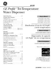
1.4 Outline Dimension<br />
130<br />
230,37<br />
Width 840<br />
Height 593 (656 with stand)<br />
Depth 130 (231 with stand)<br />
¢II[IHN$$$N[H[!$$$Nn$1$11$@I$$1N!N$%<br />
................. 84_ ...............................................................................................................<br />
Physical Characteristics :<br />
654,4<br />
Product Description<br />
111111<br />
111111<br />
111111<br />
Weight Gross Weight 24.24 Kg (without card reader) / 24.44 Kg (with card reader)<br />
Net Weight 19.4 kg (without card reader) / 19.6 Kg (with card reader)<br />
Color Defination:<br />
Front Cover(Outside flame)<br />
Front Cover(inside frame)<br />
Back cover<br />
Stand<br />
Base plate<br />
TV Box<br />
Pantone 877C<br />
Pantone Black C<br />
NCS 6502B<br />
Pantone 877 C<br />
Pantone 877 C<br />
NCS 6502B
2.0 Engineering Specifications<br />
2.1 TFT LCD Panel Specifications: AU T315XW01 V5<br />
LCD Active matrix thin-film-transistor (TFT)<br />
Signal Interface LVDS (Low Voltage Differential Signaling)<br />
(2 pixel/clock)<br />
Engineering Specifications<br />
Screen Size 31.51" Diagonal inch<br />
Effective Display size 697.68(H) x 392.26(V) mm<br />
Pixel Number 1366 x R.G.B. x 768 Pixels<br />
Color filter arrangement RGB vertical stripe<br />
Display Method Normally black<br />
Drive Method a-si TFT active matrix<br />
Pixel Pitch 0.51075 (H) x 0.51075 (W) Mm<br />
Brightness 500 cd/m 2 (typ.) cd/m 2<br />
Contrast Ratio 800:1 (typ.)<br />
650:1 (min.)<br />
Display Color 16.7M colors<br />
Response Time (Rise + Decay) 24 ins (Gray to Gray) ins
2.2 Optical Characteristics<br />
Measuring requirement<br />
Input AC Power<br />
Contrast setting<br />
Brightness setting<br />
Lighting<br />
Measurement point<br />
Distance from LCD module<br />
View of measurement machine<br />
Warm up time<br />
Measuring Equipment<br />
110[v]/60[Hz]<br />
Center<br />
Maximum<br />
Outside optical interception<br />
Center (Brightness Uniformity is 5 point)<br />
50[cm]<br />
1[degree]<br />
30[mini<br />
Video Pattern Generator Chroma 2327<br />
LCD Color Analyzer K- l0<br />
Engineerin_ Specifications
0 _tical Specification<br />
Contrast Ratio (Center<br />
of Screen)<br />
Response time<br />
Luminance of White<br />
Viewing Angle<br />
Red<br />
Chr°C°nlatricitY(cIE) _rl_e_<br />
White<br />
Hor.<br />
Ver.<br />
Luminance Uniformity<br />
CR<br />
TFR<br />
TED<br />
LWH<br />
XR<br />
YR<br />
Xc_<br />
Yc_<br />
XB<br />
YB<br />
Xw<br />
Yw<br />
O Definition of Contrast Ratio (CR):<br />
CR =<br />
x+<br />
X-<br />
y<br />
y<br />
Ox=O<br />
Viewing<br />
normal angle<br />
Gray to Gray<br />
CR>10<br />
Luminance with all pixels white<br />
Luminance with all oixels black<br />
Engineering Specifications
Engineering Specifications<br />
® Response time is the time required for the display to transfer between any two gray level.<br />
It is defined as the following figure.<br />
A.y _i_h<br />
Any darker gray level<br />
T:rl_ TrR<br />
[ fightergray level<br />
® Surface Luminance is a measurement of the active display area, 50 cm from the center<br />
of the surface in condition of displaying window pattern.<br />
LCD Module<br />
LCD Panel<br />
of the Screen<br />
Field of View = 2 °<br />
Photometer<br />
(TOPCON BM-7A)<br />
< 500 mm Light Shield Room<br />
IJ,
En_ineerin_ Specifications<br />
(b Viewing angle is the angle at which the contrast ratio is greater than 10 (CR> 10) with<br />
window pattern. The angle is determined for the horizontal or x-axis and the vertical y-axis<br />
with respect to the z-axis which is normal to the LCD surface.<br />
0X- = 90 ° X-<br />
6 o'clock<br />
0y- = 90°<br />
Normal<br />
0x = 0y = 0°<br />
0y- 0y+<br />
12 o'clock direction<br />
Oy+ = 90 °<br />
Y- x+ 0X+ = 90°<br />
® Definition of luminance uniformity 8W (5 points):<br />
8W = Maximum [C (1), C (2), C (3), C (4), C (5)] / Minimum [L (1), C (2), C (3), C (4), C<br />
(5)]<br />
0 ---<br />
..{3 256 ....<br />
m<br />
Z<br />
(1) 5!2 ....<br />
t-<br />
J<br />
_i 768 ....<br />
0<br />
1023 ....<br />
0<br />
Horizontal Line Number<br />
320 640<br />
()<br />
()<br />
I<br />
4><br />
I<br />
Active area<br />
I<br />
960<br />
I<br />
(><br />
Q<br />
1279<br />
I<br />
: test point<br />
X=l to 5
2.3 I/O Connectors<br />
I/O Table<br />
TV tuner<br />
Y2Pb2Pr2in & RCA audio(L/R) in<br />
AV Video in & RCA audio(L/R) in<br />
S-Video in & RCA audio(L/R) in<br />
D-SUB<br />
PC audio in<br />
HDMI<br />
AV Video out & audio (R/L) out<br />
Earphone<br />
Subwoofer<br />
2.4 D-Sub (Analog) Input<br />
Electrical Properties<br />
Analog R, G, B<br />
Signal level<br />
Separate sync<br />
Horizontal sync<br />
Vertical sync<br />
D-sub Pin Assignment<br />
2<br />
Red video<br />
Green Video/Sync on<br />
Green<br />
3 Blue Video<br />
4 Open<br />
5 Return<br />
*Compliant to VESA DDC.<br />
-- 0.7 Vp_p<br />
75 ohm 4-5%<br />
TTL level<br />
Positive/Negative<br />
Positive/Negative<br />
Red Video Ground<br />
7 Green Video Ground<br />
8 Blue Video Ground<br />
9 +5V (for cable detect)<br />
10 Sync Ground<br />
NTSC<br />
2 2<br />
En_ineerin_ Specifications<br />
3 3<br />
1 1<br />
1<br />
1<br />
1<br />
Open<br />
12 Data line (SDA)*<br />
13 H-Sync<br />
14 V-Sync<br />
15 Clock line (SCL)*
2.5 PC Audio Input (line-in)<br />
Input Voltage 0.7 Vp_p (typical)<br />
Output Power l0 W per channel<br />
2.6 ISP (In System Programming)<br />
En_ineerin_ Specifications<br />
- Only for Engineering BIOS update through 4-pin connector, operated by authorized<br />
technician.<br />
2.7 HDMI (High-Definition Multimedia Interface)<br />
2<br />
3<br />
4<br />
5<br />
6<br />
7<br />
TMDS DATA 2+<br />
TMDS DATA 2 Shield<br />
TMDS DATA 2-<br />
TMDS DATA 1+<br />
TMDS DATA 1 Shield<br />
TMDS DATA 1-<br />
TMDS DATA 0+<br />
2.8 Analog Compliant Timings<br />
VESA<br />
Display Mode<br />
VGA<br />
SVGA<br />
XGA<br />
SXGA<br />
640 x 480<br />
720X400<br />
800 x 600<br />
1024 x 768<br />
1280 x 1024<br />
TMDS DATA 0 Shield<br />
9 TMDS DATA 0- 16<br />
10 TMDS Clock + 17<br />
11 TMDS Clock Shield 18<br />
12 TMDS Clock- 19<br />
13 CEC (not used)<br />
14 RESERVED (N.C. on device)<br />
Analog / Digital<br />
Horizontal Frequency Vertical Frequency<br />
31.5 KHz 60 Hz<br />
37.9 KHz 72 Hz<br />
37.5 KHz<br />
43.3 KHz<br />
37.9 KHz<br />
35.1 KHz<br />
37.9 KHz<br />
48.1 KHz<br />
46.9 KHz<br />
53.7KHz<br />
48.4 KHz<br />
56.5 KHz<br />
60.0 KHz<br />
68.7KHz<br />
64.0 KHz<br />
80.0 KHz<br />
75 Hz<br />
85 Hz<br />
85 Hz<br />
56 Hz<br />
60 Hz<br />
72 Hz<br />
75 Hz<br />
85 Hz<br />
60 Hz<br />
70 Hz<br />
75 Hz<br />
85 Hz<br />
60 Hz<br />
75 Hz<br />
SCL (DDC Clock)<br />
SDA (DDC SAra)<br />
DDC/CEC Ground<br />
+5V Power<br />
Hot Plug Detect
2.9 Power Supply specification & Power Management<br />
Power Supply specification<br />
Vendor<br />
Input Voltage Range<br />
Input Frequency Range<br />
Output Voltage<br />
Output Current<br />
Power Dissipation<br />
Efficiency<br />
Power Saving Operation Method<br />
Power Consumption<br />
Power saving recovery Time<br />
2.10 Power Management<br />
FSP FSP232-4M01 (first source)<br />
AC 90 - 264 Vac<br />
47/63 Hz<br />
5V, 16V, 24V+ 5%<br />
1.2A(5V), 5.5A(12V), 5.5A(24V)<br />
-232W (max.)<br />
Functions & OSD Operation<br />
80% MIN. AT FULL LOAD, (C.V MODE),<br />
NOMINAL LINE, (110V-220V)<br />
MEASURED AFTER 30MINUTES FULL<br />
LOAD BURN-IN<br />
VESA DPMS Signaling<br />
ON Mode < 232 W (max)<br />
ACTIVE OFF < 5W<br />
ON Mode = N/A<br />
ACTIVE OFF < 3 sec<br />
This monitor will incorporate power saving modes when "power saving" is enabled via<br />
the and in response to VESA DPMS power saving signals from the host CPU. It is<br />
required that the monitor will respond identically to the VESA DPMS standby, suspend,<br />
and sleep modes with a <strong>com</strong>mon low power mode.<br />
1<br />
2<br />
3<br />
On Normal Green Normal<br />
Suspend No Display Amber < 5W<br />
Off No Display Red < 5W
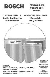
2.11 Packaging Specification<br />
Carton Box Dimension<br />
Outside dimension: 1005(W)*772(H)*305(D) mm<br />
Functions & OSD Operation<br />
42 997 SO0 _ 29_<br />
FCC Label<br />
©<br />
Model Number:LT32C1Pl<br />
h'_#ut:AC _00-240V<br />
50-60Hz 3 5A<br />
_@{s_fact_r_g ONe<br />
............................. J<br />
SIN:<br />
I I<br />
I I<br />
.............................. J<br />
{1)This device may rw_tcause hsrm_u _tede_'ece,<br />
®<br />
A<br />
C,_9<br />
...................... !
2.12 Environmental Characteristics<br />
Operating Conditions<br />
Humidity<br />
Non-Operating Conditions<br />
Altitude<br />
2.12 Safety<br />
20-80%<br />
Humidity 20-85%<br />
Non-Operating Not more than 12,000m<br />
2.12.1 Insulation Resistance<br />
Functions & OSD Operation<br />
The resistance of the insulation between the power terminal and the earth ground<br />
contact is more than 10 MR while withstanding a voltage of 3kV(DC).<br />
Test Conditions<br />
Test Criteria<br />
Voltage 3k V (dc)<br />
Resistance Value 10 M_<br />
The power terminal and the earth ground contact is more than 10M_ while<br />
withstanding a voltage of 3kV(dc).<br />
2.12.2 Insulation Dielectric Strength<br />
The evaluation conforms to safety standard of shipment area.<br />
Test Conditions<br />
Voltage 3.676k Vdc (2.6K '_ac)<br />
Time 3 sec<br />
Current 10 iliA (max)
Test Criteria<br />
Functions & OSD Operation<br />
There is no breakdown of the insulators or short circuits when applying a 2.6kVac<br />
and 2.6k "¢ac for duration of lnaxilnum 3 sec between the metallic chassis and the<br />
input power supply active and neutral terminals connected together.<br />
2.13 Regulatory Standards<br />
2.13.1 Safety<br />
2.13.2 EMI<br />
EN 60065<br />
EN 55022:1998 + Al:2000 / Limit Class B<br />
EN55024<br />
EN 60111<br />
2.13.3 Certification Logo<br />
UL<br />
FCC
3.1<br />
Function Controls<br />
Front side:<br />
3.0 Functions & OSD Operation<br />
Power Power on/off<br />
(2) Source Source select<br />
® Menu Get into OSD t\_r PC/TV mode<br />
® CH • Select channel<br />
® CH • Select channel<br />
® VOL I_ Control volume<br />
© VOL _ Control volume<br />
r_ 24<br />
® Enter Exit fiom OSD/Enter to sub-menu<br />
® LED indicator (heen for PC operating monitor and TV system.<br />
Amber t\_r no siNlat<br />
Red t\_r AC Power on<br />
Functions & OSD Operation
Back side:<br />
(_J) Y2Pb2Pr2<br />
@ Y2Pb2Pr2 Audio<br />
@ S-video<br />
@ S-video Audio<br />
:'7_ Sub-woofer<br />
Video out<br />
!_) Audio out<br />
fil!" AV in 1<br />
;1!_ AVaudio 1<br />
;1'_ AV in 2<br />
_:!" AV audio 2<br />
$1_ AV audio 3<br />
3 AV in 3<br />
$1!_ Headphone<br />
3onnecting to the Video <strong>com</strong>ponent! output terminal of the video output device<br />
Functions & OSD Operation<br />
_,udio input terminal connecting to the audio output terminal of the video output device.<br />
Sonnecting to the Video <strong>com</strong>ponent2 output terminal of the video output device<br />
_,udio input terminal connecting to the audio output terminal of the video output device.<br />
'_IC S-video input terminal connecting to the S-output terminal of the video output device.<br />
_,udio input terminal connecting to the audio output terminal of the video output device.<br />
Sonnects the sub-woofer audio in<br />
_'ideo output terminal connecting to the input terminal of the video input device<br />
The video output sources are AVI,AV2,AV3 and TV)<br />
_udio output terminal connecting to the input terminal of the audio input device<br />
The audio output sources are AVl, AV2, AV3, 73/)<br />
To connect the AV1 video source.<br />
To connect the audio out of AV1 source<br />
To connect the AV2 video source.<br />
To connect the audio out of AV2 source<br />
To connect the audio out of AV3 source<br />
To connect the AV3 video source<br />
To connect headphone<br />
Back View Functions<br />
q:) PC audioin Connect this terminal to the sound output terminal of your PC or<br />
Notebook.<br />
(2) ANT Connect the coaxial cable or antenna.<br />
® D-SUB Connects this terminal to D-sub 15 pin analog output connector of the PC<br />
3r Notebook.<br />
® HDMI Connects to HDMI output connector of DVD displayer.<br />
® AC in Connect this terminal to the power cord from AC power source.
3.2 Remote Controller<br />
TV:<br />
Pure TV Full<br />
Power Power on/off<br />
2 Display Display current inforlnation<br />
3 MTS Select TV Audio system<br />
4 Mute Turn speaker on or off<br />
5 Source Select input source<br />
6 TV Get into TV channel directly<br />
function<br />
Functions & OSD Operation<br />
7 Sound Selectsthe soundmode:Off->SRSWOW->BBE->BBE& SRSWOW (Standard model<br />
cannot selectfunction)<br />
8 Picture Picture quality select (vivid, Standard, soft, defined)<br />
9 Sleep Set the Timer to turn off the set<br />
10 Recall Back to previous channel<br />
11 CATV Enter into the channel after you select channel by number<br />
12 Number Keys Select channel by nmnber 1 12<br />
13 MENU Get into OSD menu/sub- menu<br />
14 Zoom Resize fiom 4:3 to 16:9 screen or 16:9 to 4:3 screen<br />
15 CHv/A Select channel / Up, Down lnovelnent<br />
16 VOL •/* Control the volume / Right, Left movelnent<br />
17 Enter Get into sub- menu<br />
18 PIP Select PIP/POP/Multi PIP function<br />
19 Source Select sub-picture source in PIP<br />
20 Position Select position of sub-picture in PIP<br />
21 Swap Swap sub picture to main picture<br />
22 Freeze Stop main picture
3.30SD Operating Procedures<br />
The menu consists of six main items for user's option.<br />
Include : MENU, CHv, CH A, 4VOL, VOL I_and Enter:<br />
1. Press "Menu" key into the OSD menu. Use "CHv", "CHA" to scroll the options on the menu.<br />
2. Press "Enter" to submenus,<br />
3. Use "4","D,-" to adjust the settings.<br />
4. Press "Enter" to confirm the setting.<br />
5. Press "Menu" to exit the current OSD page.<br />
3.4 PIP Structure<br />
i_il i I<br />
Z I<br />
i<br />
[ Component2<br />
Y2Pr2Pr2<br />
i<br />
i VGA<br />
] DVI<br />
Main Screen<br />
Functions & OSDOperation<br />
TV . AV1 . AV2 . AV3 . S-Video Componentt Componet2 . VGA . HDM<br />
YCbCr YPbPr I<br />
TV ..... • • ' •<br />
AV1 • • •<br />
AV2 • • •<br />
AV3 • • •<br />
S-Video • • •<br />
Componentl • •<br />
Y1CblCrl
4.1 System block diagram (1)<br />
4.0 System descriptions<br />
BLOCK D_GRAM (I_SC)<br />
22<br />
System description
4.2 System Block Diagram (2)<br />
Audio Processor ( NTSC )<br />
23<br />
System description<br />
iiiiii<br />
iiiiiiii:ii_ii_!i!!iiii_!i!ii!i_iiiii!i_iiiii!ii!ii!ii!ii!ii!i
4.3 System Circuitry<br />
4.3.1 Main board<br />
(J9) To Panel<br />
(34) To Power board<br />
(J6) To Inverter board<br />
(CNS) To IR board<br />
(J8) To Power board<br />
I(CN1) To Key Pad I<br />
4.3.2 Video board<br />
(CN4) To Main board<br />
24<br />
(J3) To RCA board<br />
System description<br />
(JP7) To Speaker<br />
(J1) To Card reader<br />
(Option)<br />
(J5) To DVD (Option)<br />
(CN7) To Video board<br />
(J2) To Video board
4.3.3 Power board<br />
To Inverter board<br />
4.3.4 Front RCA board<br />
To Video board CN2 I<br />
I To Main board .13 ]I<br />
25<br />
To AC input socket I<br />
System description<br />
To Main board J4<br />
To Main board J8 I
4.3.5 Key board<br />
4.4 Pin Configuration<br />
To Main board CN1<br />
CN1 : To Key board Connector<br />
1 NC<br />
2 +3.3 V<br />
3 NC<br />
4 VIN2<br />
5 ADC2_return<br />
6 ADC VRFE<br />
7 ADC1 return<br />
8 Vinl<br />
9 NC<br />
10 Ground<br />
CN5 : To IR board Connector<br />
1 Ground<br />
2 +5v<br />
3 IR_I<br />
4 Saving LED<br />
5 Power LED<br />
26<br />
Systemdescription
J1 : To Card Reader Connector (Option)<br />
1 +5v<br />
2 CARD IR<br />
3 Ground<br />
J2 : To Video board CN2 Connector (Component 2)<br />
1 PR out<br />
2 Ground<br />
3 PY out<br />
4 Ground<br />
5 PB out<br />
6 Ground<br />
7 Ground<br />
J3 : To Earphone Connector<br />
1 Ground<br />
2 L OUT<br />
3 Mode<br />
4 R OUT<br />
J4 : To Power board Connector<br />
1 Ground<br />
2 Ground<br />
3 Ground<br />
4 +16V<br />
5 +16V<br />
6 +16V<br />
27<br />
System description
J5 : To DVD Connector (Option)<br />
1 +5V<br />
2 +5V<br />
3 DVD_IR<br />
4 Ground<br />
J6 : To Inverter Connector<br />
1<br />
2<br />
3<br />
1NV ON/OFF (ON/OFF Control)<br />
BLACK-LIGHT (Brightness Control)<br />
Ground<br />
J7 : To S _eaker<br />
1 Speaker L+<br />
2 Speaker R+<br />
3 NC<br />
4 NC<br />
5 Speaker L-<br />
6 Speaker R-<br />
J8 : To Power board Connector<br />
1 +5VS<br />
2 +5VS<br />
3 Ground<br />
4 Ground<br />
5 Power_off<br />
28<br />
Systemdescription
J9 : To Panel Connector<br />
1<br />
2<br />
3<br />
4<br />
5<br />
6<br />
7<br />
8<br />
9<br />
10<br />
11<br />
12<br />
13<br />
14<br />
15<br />
16<br />
17<br />
18<br />
+5V<br />
+5V<br />
+5V<br />
+5V<br />
TXA0+<br />
TXA0-<br />
TXAI+<br />
TXA1-<br />
TXA2+<br />
TXA2 -<br />
Ground<br />
Ground<br />
TXAC+<br />
TXAC -<br />
Ground<br />
Ground<br />
TXA3+<br />
TXA3-<br />
29<br />
19<br />
20<br />
21<br />
22<br />
23<br />
24<br />
25<br />
26<br />
27<br />
28<br />
29<br />
30<br />
31<br />
32<br />
33<br />
34<br />
35<br />
36<br />
Ground<br />
Ground<br />
TXB0+<br />
TXB0-<br />
TXBI+<br />
TXB 1-<br />
TXB2+<br />
TXB2-<br />
Ground<br />
Ground<br />
TXBC+<br />
TXBC-<br />
Ground<br />
Ground<br />
TXB3+<br />
TXB3-<br />
Ground<br />
Ground<br />
System description
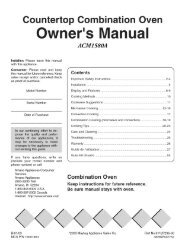
5.1 Explore Diagram<br />
5.2 Removal and Replacement<br />
5.2.1 Remove and Replace Stand<br />
5.2.2 Remove and Replace Video board<br />
5.0 Mechanical Assembly<br />
Systemdescription<br />
1. Remove Screw<br />
PN: 066-00581-00<br />
Reverse procedure for Replacement<br />
1. Remove Screws<br />
P _',_:066-00848-00<br />
1. Remove Screw<br />
PN: 066-00575-00
31<br />
1. Remove Screw<br />
PN: 066-00615-00<br />
Remove Screw<br />
P/N:066-00578-00<br />
System description<br />
1. Remove Screw<br />
PiN: :066-00844-00<br />
2. Remove Screw<br />
PiN: 066-00610-00<br />
2. Remove Screw<br />
PiN: 066-00669-00
5.2.3 Remove and Replace Rear Cover<br />
Remove Screw<br />
Relnove Screw<br />
PN: 066-00742-00<br />
System description<br />
PN: 066-00742-00 Remove P/N: 066-00850-00 Screw I<br />
Remove Screw<br />
PiN: 066-00742-00<br />
Remove the rear cover after removing all the above screws.<br />
32<br />
I Reverse procedure for Replacement
5.2.4 Remove and Replace Front RCA board Card Reader (option)<br />
5.2.5 Remove and Replace Main board<br />
2. Remove Screw<br />
P'N: 066-00653-00<br />
33<br />
1. Remove Screws<br />
PN: 066-00610-00<br />
(For Card Reader)<br />
2. Remove Screws<br />
PN: 066-00610-00<br />
System description<br />
(For front RCA board)<br />
Reverse procedure for Replacement<br />
1. Remove the connectors<br />
3. Remove Screws<br />
PiN: 066-00667-00
34<br />
Systemdescription<br />
RemoveScrew<br />
P/N:066-00614-00<br />
RemoveScrew<br />
P/N:066-00578-00<br />
I Reverse procedure for Replacement
5.2.6 Remove and Replace Power board<br />
I 2. Remove the connectors<br />
35<br />
System description<br />
1. Remove Screws<br />
P/N: 066-00614-00<br />
3. Remove Screws<br />
P/N: 066-006577-00<br />
Reverse procedure for Replacement I<br />
6. Remove Screws I
5.2.7 Remove and Replace Panel<br />
1. Remove Screw<br />
P/N: 066-00575-00<br />
and take the panel ass'y fiom fiont bezel<br />
36<br />
System description
1.Remove Inverterconnecting wire. 2.RemovePanel connecting wire.<br />
Reverse procedure for Replacement [<br />
37<br />
I 3. P/N: Remove 066-00849-00 Screw<br />
Systemdescription
Item<br />
1<br />
6.0 Troubleshooting Guide<br />
Symptom<br />
No Power, No Picture, No<br />
Backlight, No Sound<br />
No Picture, No backlight,<br />
Sound is OK.<br />
No Picture, Backlight is OK,<br />
Sound is OK.<br />
Action of Function Key<br />
abnormally<br />
Remote control problem<br />
Poor performance of picture<br />
No sound, Poor sound<br />
Inspection points<br />
1. Check Power board AC input.<br />
System description<br />
2. Check Power board DC output (+SVs, +SV, +16V).<br />
3. Check J4 of Main board and connecting wire.<br />
4. Check J8 of Main board and connecting wire.<br />
5. Check J6 of Main board and connecting wire.<br />
6. Check Main board.<br />
1. Check Power supply voltage for inverter.(24Vdc)<br />
2. Check Inverter.<br />
3. Check J6(main board) to Inverter connecting wire.<br />
4. Check Main board.<br />
1. CheckVLCD 5Von J9 connector.<br />
2. Check Panel connector.<br />
3. Check connecting wire( J9 to Panel).<br />
4. Check Main board.<br />
5. Check Panel<br />
1. Check Keyboard<br />
2. Check Key Pad.<br />
3. Check Key board to CN1 connecting wire.<br />
4. Check Main board.<br />
1. Check IRboard.<br />
2. Check IR board to CN5 connecting wire.<br />
3. Check Remote control.<br />
4. Check Main board.<br />
1. Check AltFactory Reset.<br />
2. Check Main board.<br />
3. Check Video board.<br />
4. Check CN2 of Video board connecting wire.<br />
5. Check CN7 to Video board connecting wire. (For<br />
Y,Pb,Pr)<br />
1. Check Speaker.<br />
2. Check JP7 to speaker connecting wire.<br />
3. Check Main board.<br />
4. Check Front RCAboard.<br />
5. Check J3 to Front RCA board connecting wire.<br />
38
Item Symptom Inspection points<br />
8 Can'treceiveTVorCable 1.CheckVideoboard.<br />
program<br />
Systemdescription<br />
9 CardReader problem 1. CheckJ1(Mainboard) toCardReader connecting wire.<br />
(Option) 2. CheckCardReader.<br />
3. CheckMainboard.<br />
39
Dem Part No.<br />
1 001-00015-00<br />
2 043-40074-00<br />
3 077-102t0-R0000<br />
4 077-20112-00<br />
5 077-20164-00300<br />
6 077-20346-R0000<br />
7 077-80019-00100<br />
8 083-11428-00<br />
9 083-11930-R0100<br />
10 083-31130-00<br />
11 083-31232-00000<br />
12 083-62205-R0100<br />
13 083-62206-R0100<br />
14 083-62229-00000<br />
15 300-10970-R0000<br />
16 300-10971-R0000<br />
17 300-30005-00000<br />
18 886-00188-00000<br />
19 919-00402-00<br />
20 919-30061-00<br />
21 919-37023-00<br />
22 919-37028-00<br />
23 004-14055-R0000<br />
24 004-14063-00<br />
25 004-14071-00<br />
26 004-14103-R0200<br />
27 004-14104-00000<br />
7.0 Spare Parts Material List<br />
BATTERY<br />
Part Name<br />
LABEL;Protron(PLTV-32M)<br />
BARCODELABEL(_ _ )<br />
CARTON LABEL:Prosonic<br />
LABEL;FOR HDMI LOGO<br />
gg_g+_;PLTV-30&PLTV-27<br />
_I",}_;Protron(PLTV-32M); _ _a;R 1<br />
PE<br />
CUSHION<br />
CUSHION<br />
_,_ EPE<br />
_SL_)]_ ;Protron<br />
_2 _ ;PROSONIC(PLTV-32C)<br />
CABLE;LT17B1E1<br />
POWER CORD<br />
CABLE;AUDIO<br />
CABLE(_S _;_[, *g.)<br />
BRACKET;WALL MOUNT<br />
BRACKET;TV BD AV<br />
BRACKET;AC SOCKET<br />
BRACKET;PANEL AS S'Y(AU V5)<br />
BRACKET;PW BD<br />
40<br />
Q'D" Unit Location<br />
2 PCS<br />
1 PCS<br />
1 PCS<br />
2 PCS FCC LABEL<br />
1 PCS<br />
1 PCS<br />
1 PCS<br />
1 PCS<br />
1 PCS<br />
System description<br />
1 PCS MANUAL+BATTERY<br />
1 PCS<br />
1 PCS<br />
1 PCS<br />
1 PCS<br />
1 PCS<br />
1 PCS<br />
1 PCS<br />
1 PCS<br />
1 PCS<br />
1 PCS<br />
1 PCS<br />
1 PCS<br />
8 PCS<br />
1 PCS<br />
1 PCS<br />
1 PCS<br />
1 PCS<br />
REAR COVER*8(_%
hem PartNo.<br />
28 004-14105-00000<br />
29 004-14111-00000<br />
30 004-14113-00000<br />
31 004-14144-R0100<br />
32 004-14145-R0100<br />
33 004-14147-R0000<br />
34 004-14148-R0000<br />
35 019-10007-00<br />
36 022-0065A-00500<br />
37 022-0066A-00100<br />
38 022-0067A-00000<br />
39 043-40018-00<br />
40 043-40019-00<br />
41 062-50010-00<br />
42 062-50018-00005<br />
43 062-50018-00105<br />
44 065-10037-00100<br />
45 065-10049-R0000<br />
46 065-10050-R0000<br />
47 066-00573-00<br />
48 066-00575-00<br />
49 066-00577-00<br />
50 066-00578-00<br />
51 066-00581-00<br />
52 066-00592-00<br />
53 066-00610-00<br />
54 066-00614-00<br />
55 066-00614-00100<br />
56 066-00615-00<br />
Part Name<br />
BRACKET;PANEL SIDE(AU)<br />
BRACKET;TV BD IO(AV)<br />
BRACKET;STAND NECK<br />
BRACKET;MAIN BD IO(HDMI)<br />
BRACKET;TV BD IO;TV2<br />
BRACKET;TV BD<br />
BRACKET;MAIN BD<br />
CASE;TV COVER TOP(AV _p_q)<br />
CASE;TV COVER BOTTOM;R1<br />
CASE;FRONT BEZEL ASS'Y<br />
MYLAR;LT27C 1P 1<br />
MYLAR;LT27C 1P 1<br />
Rubber foot<br />
RUBBER FOOT;RIGHT;LT32C 1P 1<br />
RUBBER FOOT;LEFT;LT32C 1P1<br />
SHIELD;POWER BD<br />
SHIELD;MAIN BD<br />
SHIELD;TV BD AV<br />
SCREW;ZINC<br />
SCREW;ZINC<br />
SCREW;W/WASHER;ZINC<br />
SCREW;W/WASHER;ZINC<br />
SCREW;W/_ _ +_ _ )4<br />
SCREW;W/TOOTH LOCK<br />
SCREW;ZINC<br />
SCREW<br />
SCREW<br />
SCREW, BLACK<br />
41<br />
Q'O- [;nit<br />
2 PCS<br />
1 PCS<br />
1 PCS<br />
1 PCS<br />
1 PCS<br />
1 PCS<br />
1 PCS<br />
1 PCS<br />
1 PCS<br />
1 PCS<br />
1 PCS<br />
1 PCS<br />
1 PCS<br />
2 PCS<br />
8 PCS<br />
Systemdescription<br />
Location<br />
Between M/B &<br />
Shield-M/B<br />
1 PCS FRONT STAND BASE<br />
1 PCS FRONT STAND BASE<br />
1 PCS<br />
1 PCS<br />
1 PCS<br />
7 PCS<br />
28 PCS<br />
8 PCS<br />
10 PCS<br />
8 PCS<br />
1 PCS<br />
6 PCS<br />
39 PCS<br />
5 PCS
Item PartNo.<br />
57 066-00653-00<br />
58 066-00667-00<br />
59 066-00742-00<br />
60 066-00844-00000<br />
61 066-00846-00000<br />
62 066-00848-00000<br />
63 066-00849-00000<br />
64 066-00851-00000<br />
65 066-00943-00000<br />
66 076-75075-00000<br />
67 076-77001-00<br />
68 083-95034-R0006<br />
69 083-95046-00006<br />
70 092-10248-00<br />
71 505-10143-00000<br />
72 508-10011-R0000<br />
73 510-00115-R0200<br />
74 511-00074-00009<br />
75 922-10133-00400<br />
76 940-00017-00000<br />
77 944-00729-001A5<br />
78 944-00732-000A5<br />
7980 944-00734-001A5<br />
81 944-00735-001A5<br />
82 944-00809-R01A5<br />
83 944-00810-000A5<br />
84 944-00816-R00A5<br />
85 971-1011B-004<br />
86 971-1027E-00000<br />
87 971-1065E-R0100<br />
PartName Q'D Unit<br />
SCREW;ZINC 2 PCS<br />
SCREW ZINC 2 PCS<br />
SCREW;BLACK 17 PCS<br />
SCREW;ZINC 2 PCS<br />
SCREW 8 PCS<br />
SCREW;BLACK 2 PCS<br />
SCREW;ZINC 10 PCS<br />
SCREW;W/WASHER;ZINC 12 PCS<br />
SCREW;ZINC 8 PCS<br />
MYLAR;CARD READER;LT32C 1P1 1 PCS<br />
_g,_ _ ga 13 PCS<br />
_ _g}g ;Meet Rohs 2 PCS<br />
g_;g}g 2 PCS<br />
BUTTON 1 PCS<br />
SPRING 8 PCS<br />
HOLDER;DIE CASTING 1 PCS<br />
PANEL;Meet Rohs 1 PCS<br />
LENS;IR;£_g_;LT32C 1P 1 1 PCS<br />
REAR COVER"C; _g+HDMI _p_,J"ASSY 1 PCS<br />
CONNECTOR WIRE;LT32C 1P 1<br />
CONNECTOR WIRE;LT32C 1P 1<br />
CONNECTOR WIRE;LT32C 1P 1<br />
CONNECTOR WIRE;LT32C 1P 1<br />
CONNECTOR WIRE; _ _'_,_ ;LT32C 1M 1<br />
CONNECTOR WIRE;LT32C1M1<br />
CONNECTOR WIRE; _ _a ;LT32C 1P 1<br />
PCBA POWER/B;4 )__OUTPUT<br />
DIP PCBA VIDEO BOARD<br />
DIP PCBA MOTHER BOARD;REV.E<br />
42<br />
1 PCS<br />
1 PCS M/B- PW/B<br />
1 PCS AC-PW/B<br />
1 PCS M/B-PW/B<br />
1 PCS M/B-PANEL<br />
1 PCS M/B-K/B<br />
1 PCS M/B-RCA/B<br />
Systemdescription<br />
Location<br />
1 PCS INVERTER-PW/B<br />
1 PCS<br />
1 SET<br />
1 SET
Item Part No.<br />
88 971-10616-00<br />
89 971-1031C-00000<br />
90 971-10579-01<br />
DIP PCBA K/B<br />
Part Name<br />
DIP PCBA IR+LED BOARD<br />
DIP FRONT RCA BOARD;REV.E<br />
Q'D Unit<br />
1 SET<br />
1 SET<br />
1 SET<br />
Approved by: Jerry Prepared by: C{iffChang<br />
43<br />
Systemdescription<br />
Location