Replacing Safety Flange - Mueller Co.
Replacing Safety Flange - Mueller Co.
Replacing Safety Flange - Mueller Co.

You also want an ePaper? Increase the reach of your titles
YUMPU automatically turns print PDFs into web optimized ePapers that Google loves.
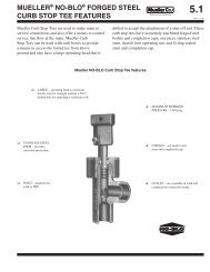
MUELLER ® IMPROVED FIRE HYDRANT<br />
REPLACING SAFETY FLANGE AND BRASS SAFETY COUPLING<br />
(ALL MODELS PRIOR TO 1962)<br />
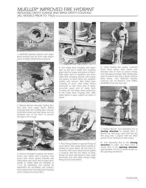
1. MUELLER Improved Hydrant with Upper<br />
Barrel knocked over by truck. Note broken<br />
pieces of <strong>Safety</strong> <strong>Flange</strong> lying on ground.<br />
4. Turn <strong>Safety</strong> Stem <strong>Co</strong>upling and Upper<br />
Stem so that slot in <strong>Safety</strong> Stem <strong>Co</strong>upling<br />
aligns with the tongue and groove of Stems.<br />
Hold Upper Stem in alignment and screw<br />
<strong>Safety</strong> Stem <strong>Co</strong>upling upward until tongue<br />
and groove of Stems firmly lock together.<br />
Tighten with wrench. With <strong>Safety</strong> Stem<br />
<strong>Co</strong>upling in place, slide <strong>Safety</strong> Sleeve<br />
downward so that lower end of Sleeve<br />
surrounds upper end of <strong>Safety</strong> Stem<br />
<strong>Co</strong>upling. Be sure <strong>Safety</strong> Sleeve projections<br />
fit into <strong>Safety</strong> Stem <strong>Co</strong>upling slots. With<br />
<strong>Safety</strong> Sleeve in place, tighten set screw in<br />
Sleeve.<br />
6. Check Stuffing Box gasket. Lubricate<br />
A-366 Brass Sleeve. Slide Sleeve over<br />
threaded area of Stem to protect O-rings<br />
from damage by threads. Place Stuffing Box<br />
plate in position and bolt to Barrel. Remove<br />
Brass Sleeve. Pour MUELLER Hydrant<br />
Lubricant into Oil Reservoir until THREE-<br />
QUARTERS of an inch from top.<br />
2. Remove Bonnet Assembly, Stuffing Box,<br />
and Stem from Upper Barrel. Before<br />
removing Stem from Stuffing Box, lubricate<br />
A-366 Brass Sleeve and slide Sleeve over the<br />
threaded area of the Stem to prevent<br />
damage to the O-rings.<br />
3. Remove damaged <strong>Co</strong>upling and Sleeve.<br />
Screw new <strong>Safety</strong> Stem <strong>Co</strong>upling onto<br />
Lower Stem down against shoulder. Slip<br />
<strong>Safety</strong> Sleeve over lower end of Upper Stem.<br />
(NOTE: IF UPPER STEM OF HYDRANT IS<br />
1-1/4” IN DIAMETER, CUT SLEEVE AS<br />
INDICATED BY LETTERING ON SLEEVE.)<br />
Screw Upper Stem into <strong>Safety</strong> Stem <strong>Co</strong>upling<br />
until it contacts the Lower Stem.<br />
5. Place <strong>Flange</strong> Gasket on exposed <strong>Flange</strong> of<br />
Lower Barrel. Place Upper Barrel carefully in<br />
position on Lower Barrel. Be sure that it is<br />
concentric with Lower Barrel and the gasket<br />
is centered. Bolt the two halves of <strong>Safety</strong><br />
<strong>Flange</strong> into place with bevel on outer edge<br />
downward and with <strong>Safety</strong> <strong>Flange</strong> snugly<br />
fitting around Lower Barrel.<br />
7. Replace Bonnet. Turn Operating Nut in<br />
closing direction to engage stem. If<br />
Bonnet has filler plug, make sure that the<br />
filler plug hole is aligned with the offset<br />
portion of the Oil Reservoir. Bolt in place.<br />
8. Turn Operating Nut in the closing<br />
direction to make sure Main Valve is<br />
closed, then in the opening direction<br />
approximately 1/4 turn to relieve tension on<br />
the operating mechanism.<br />
(<strong>Co</strong>ntinued)<br />
1
MUELLER ® IMPROVED FIRE HYDRANT<br />
REPLACING SAFETY FLANGE AND BRASS SAFETY COUPLING<br />
(SEALED OIL RESERVOIR 1962 STYLE)<br />
! CAUTION<br />
Always fill the oil reservoir with the Bonnet installed, the Hydrant in its normal upright position, and the Main Valve fully closed. If the Hydrant<br />
is filled with lubricant under any other circumstances, excess lubricant can overfill the Bonnet and create a pressure lock. This could result in<br />
damage to the Seals or Bonnet, or prevent proper Hydrant operation.<br />
1. MUELLER Improved Hydrant with Upper<br />
Barrel knocked over by truck. Note broken<br />
pieces of <strong>Safety</strong> <strong>Flange</strong> lying on ground.<br />
4. Turn <strong>Safety</strong> Stem <strong>Co</strong>upling and Upper Stem<br />
so that slot in <strong>Safety</strong> Thimble aligns with the<br />
tongue and groove of Stems. Hold Upper Stem<br />
in alignment and screw <strong>Safety</strong> Stem <strong>Co</strong>upling<br />
upward until tongue and groove of Stems firmly<br />
lock together. Tighten with wrench. With <strong>Safety</strong><br />
Stem <strong>Co</strong>upling in place, slide <strong>Safety</strong> Sleeve<br />
downward so that lower end of Sleeve<br />
surrounds upper end of <strong>Safety</strong> Stem <strong>Co</strong>upling.<br />
Be sure <strong>Safety</strong> Sleeve projections fit into <strong>Safety</strong><br />
Stem <strong>Co</strong>upling slots. With <strong>Safety</strong> Sleeve in<br />
place, tighten set screw in <strong>Safety</strong> Sleeve.<br />
6. Check Bonnet Gasket. Attach the A-366 Brass<br />
Sleeve, if it had been removed, to Upper Stem<br />
and lubricate outside to protect O-ring seals<br />
from thread damage. Place Bonnet onto Upper<br />
Barrel and assemble Bonnet bolts only hand<br />
tight. Remove Brass Sleeve. Reassemble<br />
Operating Nut* and remove Oil Plug in side of<br />
Bonnet. Pour MUELLER Hydrant Lubricant into<br />
oil reservoir until it is level with Plug. Replace Oil<br />
Plug.<br />
2. Unbolt and remove broken <strong>Safety</strong> <strong>Flange</strong><br />
from Upper Barrel. Remove Weather Cap, Hold<br />
Down Nut, and Operating Nut from Bonnet.<br />
Lubricate A-366 Brass Sleeve and slide over<br />
threaded Stem end to prevent O-ring damage.<br />
Unbolt Bonnet from Upper Barrel. Slide Upper<br />
Stem out of Bonnet. Remove damaged Stem<br />
<strong>Co</strong>upling and Sleeve from Upper and Lower<br />
Stem.<br />
3. Place new <strong>Safety</strong> Stem <strong>Co</strong>upling sleeve part<br />
onto Upper Stem. (NOTE: IF UPPER STEM OF<br />
HYDRANT IS 1-1/4” IN DIAMETER, CUT SLEEVE<br />
AS INDICATED BY LETTERING ON SLEEVE.)<br />
Screw new <strong>Safety</strong> Stem <strong>Co</strong>upling part onto<br />
Lower Stem as far as threads permit. Screw<br />
Upper Stem into <strong>Safety</strong> Stem <strong>Co</strong>upling until it<br />
contacts the Lower Stem.<br />
5. Place <strong>Flange</strong> gasket on exposed <strong>Flange</strong> of<br />
Lower Barrel. Place Upper Barrel carefully in<br />
position on Lower Barrel. Be sure that it is<br />
concentric with Lower Barrel and that gasket is<br />
centered. Bolt the two halves of <strong>Safety</strong> <strong>Flange</strong><br />
into place with bevel on outer edge downward<br />
and with <strong>Safety</strong> <strong>Flange</strong> snugly fitting around<br />
Lower Barrel.<br />
7. Replace Hold Down Nut being sure O-ring<br />
seals are in good condition at thread shoulder<br />
on outside of Hold Down Nut and on the inside<br />
where contact is made with Operating Nut.<br />
Replace Weather Cap. Tighten Bonnet Bolts.<br />
Check gasket tightness by opening one hose<br />
cap slightly before opening hydrant to bleed air.<br />
Open Hydrant until Barrel fills with water,<br />
tighten hose cap, open hydrant fully. Check<br />
gaskets, and then turn Operating Nut to fully<br />
closed position.<br />
8. Turn Operating Nut in the closing<br />
direction to make sure Main Valve is closed,<br />
then in the opening direction approximately<br />
1/4 turn to relieve tension on the operating<br />
mechanism.<br />
*TIGHTEN HOLD DOWN NUT TO 200 – 300<br />
FT-LBS OF TORQUE. IF TORQUE WRENCH IS<br />
NOT AVAILABLE, USE A 3 LB HAMMER TO<br />
STRIKE THE END OF THE A-311 WRENCH<br />
FIRMLY TWO TIMES TO ASSURE THE NUT IS<br />
PROPERLY TIGHTENED.<br />
2<br />
(<strong>Co</strong>ntinued)
MUELLER ® IMPROVED FIRE HYDRANT<br />
REPLACING SAFETY FLANGE AND STEEL SAFETY STEM COUPLING<br />
(SEALED OIL RESERVOIR 1962 STYLE)<br />
! CAUTION<br />
Always fill the oil reservoir with the Bonnet installed, the Hydrant in its normal upright position, and the Main Valve fully closed. If the Hydrant<br />
is filled with lubricant under any other circumstances, excess lubricant can overfill the Bonnet and create a pressure lock. This could result in<br />
damage to the Seals or Bonnet, or prevent proper Hydrant operation.<br />
1. MUELLER Improved Hydrant with Upper<br />
Barrel knocked over by truck. Note broken<br />
pieces of <strong>Safety</strong> <strong>Flange</strong> lying on ground.<br />
4. Assemble new <strong>Safety</strong> Stem <strong>Co</strong>upling to Upper<br />
Stem with new stainless steel Clevis Pin and new<br />
stainless steel <strong>Co</strong>tter Pin. <strong>Safety</strong> Stem <strong>Co</strong>upling<br />
should be installed with notches toward the<br />
Lower Stem. NOTE: “THIS END UP” STAMPED<br />
ON COUPLING.<br />
7. Check Bonnet Gasket. Attach the A-366 Brass<br />
Sleeve, if it had been removed, to Upper Stem<br />
and lubricate outside to protect O-ring seals<br />
from thread damage. Place Bonnet onto Upper<br />
Barrel and assemble Bonnet Bolts only hand<br />
tight. Remove Brass Sleeve. Reassemble<br />
Operating Nut and remove Oil Plug in side of<br />
Bonnet. Pour MUELLER Hydrant Lubricant into<br />
Oil Reservoir until it is level with Plug. Replace<br />
Oil Plug.<br />
2. Remove stainless steel <strong>Co</strong>tter Pin from<br />
stainless steel Clevis Pin. Remove stainless steel<br />
Clevis Pin and <strong>Safety</strong> Stem <strong>Co</strong>upling from Upper<br />
Stem. Unbolt and remove broken <strong>Safety</strong> <strong>Flange</strong><br />
from Upper Barrel. Remove Weather Cap, Hold<br />
Down Nut and Operating Nut from Bonnet.<br />
Lubricate A-366 Brass Sleeve and slide over<br />
threaded Stem End to prevent O-ring damage.<br />
Unbolt Bonnet from Upper Barrel. Slide Upper<br />
Stem out of Bonnet.<br />
3. Remove stainless steel <strong>Co</strong>tter Pin from<br />
stainless steel Clevis Pin in Lower Stem (throw<br />
away the old Clevis Pin and <strong>Co</strong>tter Pin).<br />
5. Assemble Upper Stem and new <strong>Safety</strong> Stem<br />
<strong>Co</strong>upling on to Lower Stem and retain it with<br />
new stainless steel Clevis Pin and new stainless<br />
steel <strong>Co</strong>tter Pin furnished with <strong>Safety</strong> Stem<br />
<strong>Co</strong>upling.<br />
6. Place <strong>Flange</strong> Gasket on exposed <strong>Flange</strong> of<br />
Lower Barrel. Place Upper Barrel carefully in<br />
position on Lower Barrel. Be sure that it is<br />
concentric with Lower Barrel and that Gasket is<br />
centered. Bolt the two halves of <strong>Safety</strong> <strong>Flange</strong><br />
into place with bevel on outer edge downward<br />
and with <strong>Safety</strong> <strong>Flange</strong> snugly fitting around<br />
Lower Barrel.<br />
8. Replace Hold Down Nut* being sure O-ring<br />
seals are in good condition at thread shoulder<br />
on outside of Hold Down Nut and on inside<br />
where contact is made with Operating Nut.<br />
Replace Weather Cap. Tighten Bonnet Bolts.<br />
Check Gasket tightness by opening one hose<br />
cap slightly before opening Hydrant to bleed<br />
air. Open Hydrant until Barrel fills with water,<br />
tighten hose cap, open Hydrant fully. Check<br />
gaskets, and then turn Operating Nut to fully<br />
closed position.<br />
9. Turn Operating Nut in the closing<br />
direction to make sure Main Valve is closed,<br />
then in the opening direction approximately<br />
1/4 turn to relieve tension on the operating<br />
mechanism.<br />
*TIGHTEN HOLD DOWN NUT TO 200 – 300<br />
FT-LBS OF TORQUE. IF TORQUE WRENCH IS<br />
NOT AVAILABLE, USE A 3 LB HAMMER TO<br />
STRIKE THE END OF THE A-311 WRENCH<br />
FIRMLY TWO TIMES TO ASSURE THE NUT IS<br />
PROPERLY TIGHTENED.<br />
(<strong>Co</strong>ntinued)<br />
3
MUELLER ® CENTURION FIRE HYDRANT<br />
REPLACING SAFETY FLANGE AND SAFETY STEM COUPLING<br />
! CAUTION<br />
Always fill the oil reservoir with the Bonnet installed, the Hydrant in its normal upright position, and the Main Valve fully closed. If the Hydrant<br />
is filled with lubricant under any other circumstances, excess lubricant can overfill the Bonnet and create a pressure lock. This could result in<br />
damage to the Seals or Bonnet, or prevent proper Hydrant operation.<br />
1. MUELLER Hydrant with Upper Barrel<br />
knocked over by truck. Note broken pieces of<br />
<strong>Safety</strong> <strong>Flange</strong> lying on ground.<br />
5. Assemble Upper Stem and new <strong>Safety</strong> Stem<br />
<strong>Co</strong>upling onto Lower Stem and retain it with the<br />
new stainless steel Clevis Pin and new stainless<br />
steel <strong>Co</strong>tter Pin furnished with <strong>Safety</strong> Stem<br />
<strong>Co</strong>upling.<br />
2. Remove stainless steel <strong>Co</strong>tter Pin from<br />
stainless steel Clevis Pin. Remove Clevis Pin and<br />
<strong>Safety</strong> <strong>Co</strong>upling from Upper Stem. Unbolt and<br />
remove broken <strong>Safety</strong> <strong>Flange</strong> from Upper<br />
Barrel. Remove Hold Down Nut, Anti-Friction<br />
Washer, and Operating Nut from Bonnet.<br />
Lubricate Brass Sleeve and slide over threaded<br />
Stem end to prevent O-ring damage. Unbolt<br />
Bonnet from Upper Barrel. Slide Upper Stem<br />
out of Bonnet and remove Brass Sleeve.<br />
3. Remove stainless steel <strong>Co</strong>tter Pin from<br />
stainless steel Clevis Pin in Lower Stem (throw<br />
away the old Clevis Pin and <strong>Co</strong>tter Pin).<br />
6. Install O-ring* in groove in Ground Line<br />
<strong>Flange</strong> of Upper Barrel and place Upper Barrel<br />
carefully in position on Lower Barrel. Be sure<br />
that Upper Barrel is concentric with Lower<br />
Barrel. Bolt the two halves of <strong>Safety</strong> <strong>Flange</strong> into<br />
place (with bevel on outer edge downward)<br />
and with <strong>Safety</strong> <strong>Flange</strong> snugly fitting around<br />
Lower Barrel.<br />
8. Tighten Bonnet Bolts. Unscrew one Hose<br />
Nozzle Cap slightly to bleed air. Open Hydrant<br />
fully. Tighten the Hose Nozzle Cap when water<br />
starts flowing and check all <strong>Flange</strong> connections<br />
for leaks. Turn Operating Nut to fully closed<br />
position and remove Hose Nozzle Cap to allow<br />
Barrel to drain. Replace Hose Nozzle Cap.<br />
9. Turn Operating Nut in closing direction to<br />
make sure Main Valve is closed tightly, then turn<br />
in opening direction approximately 1/4 turn<br />
to relieve tension on operating mechanism.<br />
*TO DETERMINE CORRECT O-RINGS FOR<br />
BONNET AND GROUND LINE FLANGES,<br />
WHICH ARE SIMILAR IN APPEARANCE:<br />
SMALLER DIAMETER O-RING IS USED AT<br />
BONNET FLANGE; LARGER AT GROUND<br />
LINE FLANGE.<br />
**TIGHTEN HOLD DOWN NUT TO 200 –<br />
300 FT-LBS OF TORQUE. IF TORQUE<br />
WRENCH IS NOT AVAILABLE, USE A 3 LB<br />
HAMMER TO STRIKE THE END OF THE A-311<br />
WRENCH FIRMLY TWO TIMES TO ASSURE<br />
THE NUT IS PROPERLY TIGHTENED.<br />
4<br />
4. Assemble new <strong>Safety</strong> Stem <strong>Co</strong>upling to Upper<br />
Stem with new stainless steel Clevis Pin and new<br />
stainless steel <strong>Co</strong>tter Pin. <strong>Safety</strong> Stem <strong>Co</strong>upling<br />
should be installed with notches towards the<br />
Lower Stem. NOTE: “THIS END UP” STAMPED<br />
ON COUPLING.<br />
7. Check Bonnet O-ring* for proper position and<br />
condition. Attach Brass Sleeve to Upper Stem<br />
and lubricate outside to protect O-ring Seals<br />
from thread damage. Place Bonnet onto Upper<br />
Barrel and assemble Bonnet Bolts only handtight.<br />
Remove Brass Sleeve. Reassemble<br />
Operating Nut, Anti-Friction Washer, and Hold<br />
Down Nut**. Be sure O-ring Seals are in good<br />
condition at thread shoulder on outside of Hold<br />
Down Nut and on inside where contact is made<br />
with Operating Nut. Remove Oil Filler Plug in<br />
side of Bonnet. Pour MUELLER Hydrant<br />
Lubricant into Oil Reservoir until it is level with<br />
the Oil Filler Hole. Replace Oil Filler Plug.<br />
Form 9160 Rev. 11/05-4M-1<br />
Printed in U.S.A<br />
© 2005 <strong>Mueller</strong> <strong>Co</strong>.