LS-135 & LS-150 Operator Manual - Welch Allyn
LS-135 & LS-150 Operator Manual - Welch Allyn
LS-135 & LS-150 Operator Manual - Welch Allyn

You also want an ePaper? Increase the reach of your titles
YUMPU automatically turns print PDFs into web optimized ePapers that Google loves.
ASSEMBLY INSTRUCTIONS FOR <strong>LS</strong>-<strong>135</strong> & <strong>LS</strong>-<strong>150</strong><br />
WALL MOUNT MODE<strong>LS</strong><br />
Required tools for assembly: Electric drill, 3mm (1/8”) and 4.7mm (3/16”) diameter drill bits, #2 phillips screwdriver, bubble level,<br />
linear scale.<br />
Wall Unit<br />
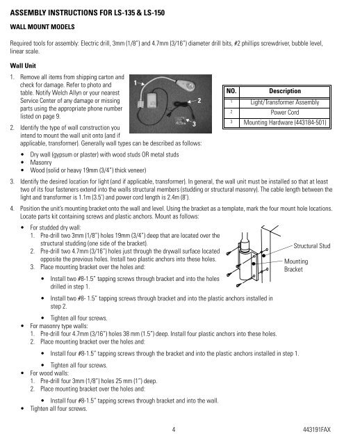
1. Remove all items from shipping carton and<br />
check for damage. Refer to photo and 1<br />
table. Notify <strong>Welch</strong> <strong>Allyn</strong> or your nearest<br />
NO.<br />
Description<br />
Service Center of any damage or missing<br />
2<br />
1 Light/Transformer Assembly<br />
parts using the appropriate phone number<br />
2 Power Cord<br />
listed on page 9.<br />
3<br />
3<br />
Mounting Hardware (443184-501)<br />
2. Identify the type of wall construction you<br />
intend to mount the wall unit onto (and if<br />
applicable, transformer). Generally wall types can be described as follows:<br />
• Dry wall (gypsum or plaster) with wood studs OR metal studs<br />
• Masonry<br />
• Wood (solid or heavy 19mm (3/4”) thick veneer)<br />
3. Identify the desired location for light (and if applicable, transformer). In general, the wall unit must be installed so that at least<br />
two of its four fasteners extend into the walls structural members (studding or structural masonry). The cable length between the<br />
light and transformer is 1.1m (3.5’) and power cord length is 2.4m (8’).<br />
4. Position the unit’s mounting bracket onto the wall and level. Using the bracket as a template, mark the four mount hole locations.<br />
Locate parts kit containing screws and plastic anchors. Mount as follows:<br />
• For studded dry wall:<br />
1. Pre-drill two 3mm (1/8”) holes 19mm (3/4”) deep that are located over the<br />
structural studding (one side of the bracket).<br />
2. Pre-drill two 4.7mm (3/16”) holes just through the drywall surface located<br />
opposite the previous holes. Install two plastic anchors into these holes.<br />
3. Place mounting bracket over the holes and:<br />
• Install two #8-1.5” tapping screws through bracket and into the holes<br />
drilled in step 1.<br />
• Install two #8- 1.5” tapping screws through bracket and into the plastic anchors installed in<br />
step 2.<br />
• Tighten all four screws.<br />
• For masonry type walls:<br />
1. Pre-drill four 4.7mm (3/16”) holes 38 mm (1.5”) deep. Install four plastic anchors into these holes.<br />
2. Place mounting bracket over the holes and:<br />
• Install four #8-1.5” tapping screws through the bracket and into the plastic anchors installed in step 1.<br />
• Tighten all four screws.<br />
• For wood walls:<br />
1. Pre-drill four 3mm (1/8”) holes 25 mm (1”) deep.<br />
2. Place mounting bracket over the holes and:<br />
• Install four #8-1.5” tapping screws through bracket and into the wall.<br />
• Tighten all four screws.<br />
Structural Stud<br />
Mounting<br />
Bracket<br />
4 443191FAX