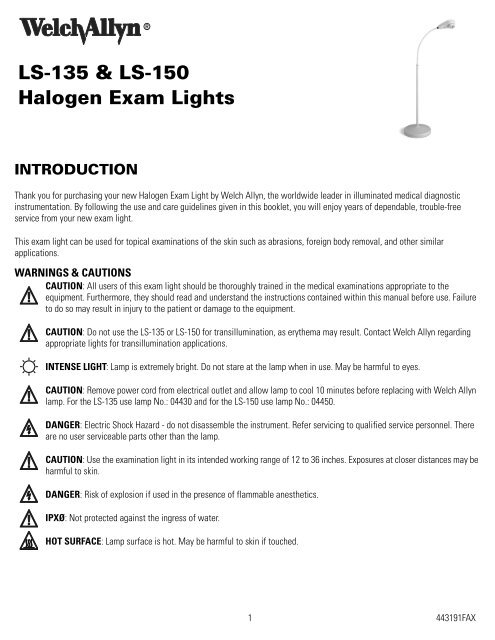
LS-135 & LS-150 Operator Manual - Welch Allyn
LS-135 & LS-150 Operator Manual - Welch Allyn
LS-135 & LS-150 Operator Manual - Welch Allyn

You also want an ePaper? Increase the reach of your titles
YUMPU automatically turns print PDFs into web optimized ePapers that Google loves.
<strong>LS</strong>-<strong>135</strong> & <strong>LS</strong>-<strong>150</strong><br />
Halogen Exam Lights<br />
INTRODUCTION<br />
Thank you for purchasing your new Halogen Exam Light by <strong>Welch</strong> <strong>Allyn</strong>, the worldwide leader in illuminated medical diagnostic<br />
instrumentation. By following the use and care guidelines given in this booklet, you will enjoy years of dependable, trouble-free<br />
service from your new exam light.<br />
This exam light can be used for topical examinations of the skin such as abrasions, foreign body removal, and other similar<br />
applications.<br />
WARNINGS & CAUTIONS<br />
CAUTION: All users of this exam light should be thoroughly trained in the medical examinations appropriate to the<br />
equipment. Furthermore, they should read and understand the instructions contained within this manual before use. Failure<br />
to do so may result in injury to the patient or damage to the equipment.<br />
CAUTION: Do not use the <strong>LS</strong>-<strong>135</strong> or <strong>LS</strong>-<strong>150</strong> for transillumination, as erythema may result. Contact <strong>Welch</strong> <strong>Allyn</strong> regarding<br />
appropriate lights for transillumination applications.<br />
INTENSE LIGHT: Lamp is extremely bright. Do not stare at the lamp when in use. May be harmful to eyes.<br />
CAUTION: Remove power cord from electrical outlet and allow lamp to cool 10 minutes before replacing with <strong>Welch</strong> <strong>Allyn</strong><br />
lamp. For the <strong>LS</strong>-<strong>135</strong> use lamp No.: 04430 and for the <strong>LS</strong>-<strong>150</strong> use lamp No.: 04450.<br />
DANGER: Electric Shock Hazard - do not disassemble the instrument. Refer servicing to qualified service personnel. There<br />
are no user serviceable parts other than the lamp.<br />
CAUTION: Use the examination light in its intended working range of 12 to 36 inches. Exposures at closer distances may be<br />
harmful to skin.<br />
DANGER: Risk of explosion if used in the presence of flammable anesthetics.<br />
IPXØ: Not protected against the ingress of water.<br />
HOT SURFACE: Lamp surface is hot. May be harmful to skin if touched.<br />
1 443191FAX
Guidelines for the safe use of the <strong>LS</strong>-<strong>135</strong> & <strong>LS</strong>-<strong>150</strong> include:<br />
General good practices to minimize risk of harm to the skin from optical radiation hazards include: minimizing illumination<br />
intensity at the tissue examination site, minimizing exposure times, and taking additional precautions when skin sensitivity<br />
has been altered through tissue trauma or the use of anesthesia.<br />
General good practices to minimize risk of harm to the eyes from optical radiation hazards include: avoiding looking at bright<br />
light sources and their reflections, and protecting eyes where normal pupil sizes and aversion responses are not present.<br />
SWITCH: Switch operation is described as follows:<br />
Off position when rocker switch is oriented towards this marking.<br />
On or full light intensity position.<br />
On or low light intensity position (<strong>LS</strong>-<strong>135</strong> only).<br />
NOTE: This product complies with current required standards for electromagnetic interference and should not interfere<br />
with other equipment or be affected by other compliant devices. As a precaution, avoid using this device in close proximity to<br />
other equipment.<br />
ASSEMBLY INSTRUCTIONS FOR <strong>LS</strong>-<strong>135</strong> & <strong>LS</strong>-<strong>150</strong><br />
FLOOR STAND MODE<strong>LS</strong><br />
NOTE: Follow the assembly instructions listed below and their corresponding photographs.<br />
Required tools for assembly: Phillips #2 or #3 screwdriver.<br />
1. Remove all items from the shipping carton. Check for damage or missing components. Refer to photo 1 and table 1. Notify <strong>Welch</strong><br />
<strong>Allyn</strong>, or your nearest Service Center of any damage or missing parts using the appropriate phone number listed on the back.<br />
2. Using the shipping box as an assembly aid; place the base (item 1) on its side oriented in the box as shown in photo 2a.<br />
3. Obtain the pole (item 3). Identify and orient the pole’s flange end with wire harness to the base and feed wire harness through<br />
base center hole as shown in photo 2b. Align wire harness into notch in base as shown in photo 3, then seat pole into base.<br />
EXERCISE CARE WHEN INSERTING POLE AND HARNESS INTO BASE. DO NOT PINCH WIRES.<br />
4. Connect pole’s wire harness connector to the corresponding connector in the base as shown in photo 4. Align and press firmly<br />
into place.<br />
5. From the parts kit, obtain the base cover plate and attach the remaining wire connector to the corresponding tab located on the<br />
cover plate. Refer to photo 5.<br />
6. From the parts kit, obtain the screw and external lockwasher and install through the plate, place the plate into the base, threading<br />
screw clockwise into pole. Tighten firmly, using screwdriver. Refer to photo 6.<br />
7. With the base/pole still lying on its side, gently pull the electrical connector from inside of the pole using the twist tie. Remove<br />
and discard twist tie. Refer to photo 7. Orient the Luminaire-flexible arm assembly’s electrical connector to the remaining pole<br />
electrical connector and connect each by firmly pressing together. Refer to photo 8.<br />
8. Connect the flexible arm to the pole by lining up the slots on the black plastic connector (nearest the electrical connector) above<br />
the pole cut outs. Push flexible arm into pole until it clicks into place. Refer to photo 9.<br />
9. Prior to plugging the unit into the appropriate outlet, inspect the lamp to insure that it has not become unseated during shipment<br />
(Refer to photo 10). If the lamp is not properly seated in the lamp housing, use your fingertips to gently press against the<br />
protective cover glass of the lamp to spring the lamp back into the proper position. If the lamp can not be easily reseated by this<br />
method, refer to the Lamp Replacement instructions to open the Lamp Housing and reseat the lamp.<br />
10. Stand light assembly up onto its base and plug into an appropriate outlet. Please refer to warnings and caution section as well as<br />
the operations section prior to use.<br />
2 443191FAX
3<br />
2<br />
No<br />
Description<br />
1<br />
Base Assembly<br />
2<br />
Luminaire-Flexible Arm Assembly<br />
4<br />
#1<br />
1<br />
3<br />
Pole Assembly<br />
4<br />
Parts Kit<br />
• Base Cover Plate<br />
• Screw 1/4-20 x 1” Phillips<br />
•1/4” External Lockwasher (443062-501)<br />
#2A<br />
Table #1<br />
#2B #3 #4<br />
#5<br />
#6<br />
#7<br />
Pole Cut Out<br />
#8 #9<br />
#10<br />
3 443191FAX
ASSEMBLY INSTRUCTIONS FOR <strong>LS</strong>-<strong>135</strong> & <strong>LS</strong>-<strong>150</strong><br />
WALL MOUNT MODE<strong>LS</strong><br />
Required tools for assembly: Electric drill, 3mm (1/8”) and 4.7mm (3/16”) diameter drill bits, #2 phillips screwdriver, bubble level,<br />
linear scale.<br />
Wall Unit<br />
1. Remove all items from shipping carton and<br />
check for damage. Refer to photo and 1<br />
table. Notify <strong>Welch</strong> <strong>Allyn</strong> or your nearest<br />
NO.<br />
Description<br />
Service Center of any damage or missing<br />
2<br />
1 Light/Transformer Assembly<br />
parts using the appropriate phone number<br />
2 Power Cord<br />
listed on page 9.<br />
3<br />
3<br />
Mounting Hardware (443184-501)<br />
2. Identify the type of wall construction you<br />
intend to mount the wall unit onto (and if<br />
applicable, transformer). Generally wall types can be described as follows:<br />
• Dry wall (gypsum or plaster) with wood studs OR metal studs<br />
• Masonry<br />
• Wood (solid or heavy 19mm (3/4”) thick veneer)<br />
3. Identify the desired location for light (and if applicable, transformer). In general, the wall unit must be installed so that at least<br />
two of its four fasteners extend into the walls structural members (studding or structural masonry). The cable length between the<br />
light and transformer is 1.1m (3.5’) and power cord length is 2.4m (8’).<br />
4. Position the unit’s mounting bracket onto the wall and level. Using the bracket as a template, mark the four mount hole locations.<br />
Locate parts kit containing screws and plastic anchors. Mount as follows:<br />
• For studded dry wall:<br />
1. Pre-drill two 3mm (1/8”) holes 19mm (3/4”) deep that are located over the<br />
structural studding (one side of the bracket).<br />
2. Pre-drill two 4.7mm (3/16”) holes just through the drywall surface located<br />
opposite the previous holes. Install two plastic anchors into these holes.<br />
3. Place mounting bracket over the holes and:<br />
• Install two #8-1.5” tapping screws through bracket and into the holes<br />
drilled in step 1.<br />
• Install two #8- 1.5” tapping screws through bracket and into the plastic anchors installed in<br />
step 2.<br />
• Tighten all four screws.<br />
• For masonry type walls:<br />
1. Pre-drill four 4.7mm (3/16”) holes 38 mm (1.5”) deep. Install four plastic anchors into these holes.<br />
2. Place mounting bracket over the holes and:<br />
• Install four #8-1.5” tapping screws through the bracket and into the plastic anchors installed in step 1.<br />
• Tighten all four screws.<br />
• For wood walls:<br />
1. Pre-drill four 3mm (1/8”) holes 25 mm (1”) deep.<br />
2. Place mounting bracket over the holes and:<br />
• Install four #8-1.5” tapping screws through bracket and into the wall.<br />
• Tighten all four screws.<br />
Structural Stud<br />
Mounting<br />
Bracket<br />
4 443191FAX
TRANSFORMER<br />
Mount the transformer to the wall using the hardware provided and integral brackets on the back of the transformer. Locate the<br />
transformer an appropriate distance from the light assembly, but within 2.4m (8’) from a suitable outlet.<br />
NOTE: For studded dry wall, identify a stud location (preferably on the same stud used to<br />
mount the light assembly). If a stud location is not available, you can use drywall only<br />
mounting as described below.<br />
3. Place the transformer at the desired height and mark a short horizontal line<br />
1.9 cm (3/4”)<br />
corresponding to the top of the transformer. From this line, mark a vertical and plumb line<br />
down approximately 12cm (5”).<br />
8 cm (3 1/8”)<br />
4. Mark hole location one 1.9 cm (3/4”) down from the horizontal line. Mark hole location<br />
two 8 cm (3 1/8”) down from hole location one. Refer to figure.<br />
• For dry wall over a stud or wood:<br />
1. Pre-drill two 3mm (1/8”) holes 19mm (3/4”) deep that are located over the structural studding.<br />
2. Screw two #8 1.5” tapping screws into wall allowing the screw heads to protrude 2.3mm (11/32”).<br />
• For dry wall only or masonry:<br />
1. Pre-drill two 4.7mm (3/16”)holes just through the drywall surface or 38mm (1.5”) into masonry. Install two plastic anchors<br />
into these holes.<br />
2. Install two #8-1.5” tapping screws into the plastic anchors allowing the screw heads to protrude 2.3mm (11/32”).<br />
OPERATION OF FLEXIBLE ARM<br />
Your new <strong>LS</strong>-<strong>135</strong> & <strong>LS</strong>-<strong>150</strong> light has been carefully designed to give you optimum performance to enable you to easily articulate and<br />
place the light exactly where you need it. These design attributes include:<br />
• The lamp has been offset at a 12° angle relative to the Luminaire housing, allowing the physician an unobstructed view of the<br />
field of interest.<br />
• A pole to flexible arm joint that allows the flexible arm to be freely rotated about the pole 270°.<br />
• A flexible arm to Luminaire joint that allows rotation of the Luminaire about the flexible arm 300°.<br />
• A 24” flexible arm that allows you to easily articulate and hold the Luminaire in an infinite number of positions.<br />
Please use the following guidelines for proper articulation of the flexible arm:<br />
• The flexible arm should be articulated (bent), NOT TWISTED. Twisting of the flexible arm beyond its rotation<br />
stops will decrease the life of the arm and can cause it to lose its ability to hold position.<br />
• Failure of the flexible arm due to twisting may void the warranty.<br />
Special Note: We recommend that you DO NOT acutely bend the flexible arm as shown to the right.<br />
LAMP REPLACEMENT<br />
Disconnect power cord from electrical outlet prior to replacement.<br />
Allow lamp to cool 10 minutes prior to replacement.<br />
1. Exposing the Lamp (Refer to photo 1)<br />
• Turn power switch to the off (“ ”) position and unplug power cord from outlet.<br />
• Rotate Light Assembly so that the lamp points up (towards ceiling).<br />
• Completely loosen screw in Lamp Housing and lift to expose the Lamp .<br />
5 443191FAX
2. Freeing the Lamp and Lamp Socket (Refer to photo 2)<br />
• Release the Lamp Retaining Wire from the Lamp Housing by pushing on wire “ears” towards Lamp Socket and swing<br />
out as shown to free the Lamp and Lamp Socket .<br />
3. Removing the Lamp Socket (Refer to photos 3 and 4)<br />
• Hold the Lamp by its outer rim. Grasp the white sides of the Lamp Socket as shown, pull on the Lamp Socket while<br />
rocking it slightly to remove it from the Lamp . Do not pull on Lamp Socket Wires .<br />
4. Install the new Lamp<br />
• Verify that the lamp number located on the metal plate inside the Light Assembly (photo #2) matches the replacement<br />
lamp number.<br />
• Replace Lamp and reattach Lamp Retaining Wire to Lamp Housing .<br />
• Align Lamp pins to Lamp Socket holes and reconnect Lamp Socket.<br />
• Reinstall Lamp Housing onto Light Assembly by first engaging Lamp Housing tab (opposite screw) into Light Assembly.<br />
Fully tighten screw.<br />
• Reconnect Power cord and verify Lamp operation.<br />
<br />
# 1<br />
# 3<br />
<br />
<br />
<br />
<br />
# 2 # 4<br />
<br />
<br />
<br />
<br />
<br />
CLEANING<br />
1. Unplug the unit prior to cleaning.<br />
2. The entire unit can be wiped down with a cloth slightly dampened with a mild solution of detergent and water. Wipe the unit dry<br />
with a clean, dry cloth. Be careful not to allow moisture to enter into the unit or allow the plug prongs to get wet.<br />
3. Do not plug the light back into the electrical outlet until the light is thoroughly dry.<br />
NOTE: Do not sterilize the unit.<br />
CAUTION: Do not immerse in cleaning solutions.<br />
WARRANTY<br />
<strong>Welch</strong> <strong>Allyn</strong> will repair or replace, free of charge, any parts of its own manufacture that prove to be defective for reasons other than<br />
misuse, neglect, damage in shipment, or normal wear. This warranty is in effect for one year from the original date of purchase.<br />
6 443191FAX
CASTER BASE ACCESSORY ASSEMBLY INSTRUCTIONS<br />
NOTE: The Exam Light must be assembled before the Caster Base Accessory is attached.<br />
Attachment Instructions:<br />
Place styrofoam block from accessory packaging box on floor. Then place Caster Base Accessory on<br />
center of block so that casters are not touching the floor.<br />
Figure 1.<br />
Flexible arm in<br />
neutral position<br />
Position the Exam Light flexible arm in neutral position as shown in Figure 1.<br />
Place the Exam Light base into Caster Base Accessory centering power cord between two wire<br />
frame legs, as shown in Figure 2. The Exam Light base should rest on top of bent legs on the opposite side.<br />
Place hand and foot as shown in Figure 3. Use your foot to push the Exam Light base down firmly until the base engages into the wire<br />
frame.<br />
NOTE: Do not force base into place by pushing down on the Light pole or pulling on flexible arm.<br />
Check to insure that the Exam Light is assembled correctly with the Caster Base Accessory. To do this, lay the Exam light over on its<br />
side and verify that the Caster Base Assembly’s wire frame is interlocked into the notches of the Exam Light Base (see Figure 4). If<br />
they are not interlocked, grasp the Exam Light Base with one hand and one leg of the Caster Base Accessory with the other hand, and<br />
turn in opposite directions until the Caster Base Accessory locks into the Exam Light Base notches.<br />
Figure 2. Base fitted into<br />
two bent legs<br />
Figure 3. Push base into<br />
place with foot. Do not force<br />
using pole.<br />
Figure 4. Caster Base Accessory<br />
assembled correctly with Exam<br />
Light Base.<br />
Detachment Instructions:<br />
Place locking casters in locked position.<br />
Place foot on one of the five legs of the metal frame. Then hold pole at the top near flexible arm and pole connection.<br />
Simultaneously, lift and push the <strong>LS</strong>-<strong>135</strong> & <strong>LS</strong>-<strong>150</strong> Exam Light away from you, releasing the base from the Caster Base Accessory.<br />
NOTE: Do not place foot on base while pushing and pulling. Do not pull on flexible arm.<br />
7 443191FAX
When ordering replacement parts for your Caster Base Accessory, please use the following numbers:<br />
440094 Caster with brake<br />
Caster Base Frame<br />
Washers<br />
OR<br />
440095 Caster without brake<br />
No. 440094 Caster with brake, Acorn Nut and two Washers<br />
No. 440095 Caster without brake, Acorn Nut and two Washers<br />
TABLE CLAMP ACCESSORY ASSEMBLY<br />
1. Securely tighten the clamp (A) to the chosen mounting surface.<br />
2. Align the holes in the mounting bracket (B) on the light with the holes in the table clamp.<br />
Using the wrench provided, install the four screws provided and tighten.<br />
SPECIFICATION<br />
Leakage Current: The products listed within this manual comply<br />
with the agency requirements listed below.<br />
Approximate Physical Dimensions<br />
9.5 cm<br />
(3.75”)<br />
Environment:<br />
Transport/Storage:<br />
Operating:<br />
-20°C - 49°C, 10°C - 35°C<br />
10% - 95% R.H. Max, 30% - 75% R.H. Max,<br />
500hPa - 1060hPa Altitude<br />
500hPa - 1060hPa Altitude<br />
86 cm<br />
(34”)<br />
23 cm<br />
(9”)<br />
12°<br />
Class I Equipment<br />
Continuous Operation<br />
63 cm<br />
(25”)<br />
C<br />
US<br />
ETL listed:<br />
UL2601-1,<br />
CSA C22.2 No. 601.1,<br />
IEC 60601-1, AS 3200.1.<br />
IEC 60601-1-2<br />
89 cm<br />
(35”)<br />
N344<br />
Australia EMC Framework Compliance<br />
Ø 36 cm<br />
(Ø14”)<br />
8 443191FAX
The CE mark on this product indicates that it has been tested to and conforms with the provisions noted within the 89/336/<br />
EEC Electromagnetic Compatibility Directive.<br />
Authorized European Representative Address:<br />
European Regulatory Manager<br />
<strong>Welch</strong> <strong>Allyn</strong>, LTD.<br />
Navan Business Park<br />
Dublin Road<br />
Navan, County Meath, Republic of Ireland<br />
Telephone: 353-46-67700<br />
Fax: 353-46-27128<br />
SERVICE INFORMATION<br />
For Technical Support or to obtain return instructions, please contact your nearest <strong>Welch</strong> <strong>Allyn</strong> service center listed below:<br />
<strong>Welch</strong> <strong>Allyn</strong>, Inc.<br />
<strong>Welch</strong> <strong>Allyn</strong>, GmbH PSC<br />
4341 State Street Road Zollerstrasse 2-4<br />
Skaneateles Falls, NY 13153-0220<br />
72417 Juningen, Germany<br />
Phone: 1-800-535-6663 Phone: 011-49-7477-927186<br />
Fax: 1-315-685-4653 Fax: 011-49-7477-927293<br />
<strong>Welch</strong> <strong>Allyn</strong>, Ltd. - Canada<br />
<strong>Welch</strong> <strong>Allyn</strong>, LTD - Singapore<br />
160 Matheson Blvd. E., Unit #2 300 Beach Road<br />
Mississauga, Ontario Canada L4Z 1V4 The Concourse #25-08<br />
Phone: 1-905-890-0004 Singapore 199555<br />
Fax: 1-905-890-0008 Phone: 011-656-291-0882<br />
Fax: 011-656-291-5780<br />
<strong>Welch</strong> <strong>Allyn</strong>, Ltd. - UK<br />
Cublington Road<br />
<strong>Welch</strong> <strong>Allyn</strong> China Service Center<br />
Aston Abbots, Buckinghamshire<br />
Room 708, Central Plaza<br />
England HP22 4ND<br />
No. 227 Huang Pi Road<br />
Phone: 011-0207-365-6780<br />
Huang Pi District<br />
Fax: 011-0207-365-9694 Shanghai 200003<br />
China<br />
<strong>Welch</strong> <strong>Allyn</strong> France Phone: 011-86-21-6327-9631<br />
814 rue Charles de Gaulle Fax: 011-86-21-6327-9632<br />
77100 Mareuil les Meaux<br />
France<br />
<strong>Welch</strong> <strong>Allyn</strong>, Ltd. - Australia<br />
Phone: 011-33-1-6009-3366 Metro Center Unit 5<br />
Fax: 011-33-1-6009-6797<br />
38-46 South Street<br />
Rydalmere NSW 2116, Australia<br />
Phone: 011-612-9638-3000<br />
Fax: 011-612-9638-3500<br />
For service in Latin America and the Caribbean region, contact:<br />
MD International<br />
11300 N.W. 41st Street<br />
Miami, FL 33178 USA<br />
Phone: 1-305-669-9003<br />
Fax: 1-305-669-1971<br />
9 443191FAX
ORDERING INFORMATION<br />
Catalog #<br />
Description<br />
04450 Halogen replacement lamp for <strong>LS</strong>-<strong>150</strong> Halogen Exam Light<br />
04430 Halogen replacement lamp for <strong>LS</strong>-<strong>135</strong> Halogen Exam Light<br />
44350 Caster base accessory, <strong>LS</strong>-<strong>135</strong> & <strong>LS</strong>-<strong>150</strong> Halogen Exam Light<br />
(Floor Stand Models Only)<br />
44101 Table Clamp Accessories (Wall mount Models Only)<br />
44301 Rail Mount Accessory (Wall mount Models Only)<br />
DISASSEMBLY INSTRUCTIONS<br />
If returning a floor stand unit for service, disassemble the flexible arm from the pole to prevent damage as follows:<br />
1. Turn the power switch to the OFF position ( ) and unplug the cord from the outlet.<br />
2. Using a small flat head screwdriver, CAREFULLY pull back the tabs at the top of the pole slightly - just enough to disengage<br />
them from the black plastic insert in the pole.<br />
3. Pull up on the bottom end of the flexible arm. Unplug the electrical connector and remove Luminaire-Flexible Arm assembly<br />
from the pole.<br />
4. Tilt the pole/base onto its side and unscrew the large phillips head screw located on the bottom center of the base.<br />
5. Remove the metal base cover plate and disconnect the connector attached to it.<br />
6. Disconnect the remaining electrical connector from the base and pull the pole out of the base.<br />
7. Securely wrap the three components (base, pole, and Luminaire assembly) and loose parts in suitable protective packaging<br />
for shipment to your authorized service center.<br />
If returning a wall mount unit for service, disassemble as follows:<br />
1. Turn the power switch to the OFF position ( ) and unplug the cord from the outlet.<br />
2. Pull up on transformer to remove it from its mounting screws.<br />
3. Unscrew the four screws mounting the unit to the wall. For units fitted with the table clamp accessory, simply remove clamp<br />
from the table.<br />
4. Securely wrap the components (lamp assembly and transformer) in suitable protective packaging for shipment to your<br />
authorized service center.<br />
NOTE: This product contains no materials classified as hazardous. Therefore, its disposal is not deemed as harmful to the<br />
environment or health risk to individuals disposing of the product. As a precaution, it is recommended you contact your local disposal<br />
and/or recycling authority for information regarding the disposal of the equipment.<br />
10 443191FAX
Model Input Output<br />
Fuse<br />
(3)<br />
Wattage<br />
Intensity<br />
Spot Size<br />
@ 65 cm<br />
(24”)<br />
Working<br />
Distance<br />
Color<br />
Temperature<br />
Lamp<br />
Life<br />
Total<br />
Weight<br />
Cord<br />
Length<br />
44300 120v~60Hz,<br />
400mA<br />
12v~2.9A 250v,<br />
500mA<br />
35w 525fc (1) 29 cm<br />
(11.4”)<br />
30.5 cm min<br />
(12” min) (2)<br />
3000K 5,000<br />
hrs (4)<br />
7.8 kg<br />
(17.3 lbs)<br />
2.9 M<br />
(9.5’)<br />
44302 230v~50Hz,<br />
250mA<br />
12v~2.9A 250v,<br />
315mA<br />
35w 525fc (1) 29 cm<br />
(11.4”)<br />
30.5 cm min<br />
(12” min) (2)<br />
3000K 5,000<br />
hrs (4)<br />
7.8 kg<br />
(17.3 lbs)<br />
2.9 M<br />
(9.5’)<br />
44303 100v~50/<br />
60Hz,<br />
500mA<br />
12v~2.9A 250v,<br />
630mA<br />
35w 525fc (1) 29 cm<br />
(11.4”)<br />
30.5 cm min<br />
(12” min) (2)<br />
3000K 5,000<br />
hrs (4)<br />
7.8 kg<br />
(17.3 lbs)<br />
2.9 M<br />
(9.5’)<br />
44304 230/<br />
240v~50Hz,<br />
250mA<br />
12v~2.9A 250v,<br />
315mA<br />
35w 525fc (1) 29 cm<br />
(11.4”)<br />
30.5 cm min<br />
(12” min) (2)<br />
3000K 5,000<br />
hrs (4)<br />
7.8 kg<br />
(17.3 lbs)<br />
2.9 M<br />
(9.5’)<br />
44306 240v~50Hz,<br />
250mA<br />
12v~2.9A 250v,<br />
315mA<br />
35w 525fc (1) 29 cm<br />
(11.4”)<br />
30.5 cm min<br />
(12” min) (2)<br />
3000K 5,000<br />
hrs (4)<br />
7.8 kg<br />
(17.3 lbs)<br />
2.9 M<br />
(9.5’)<br />
44310 120v~60Hz,<br />
400mA<br />
12v~2.9A 250v,<br />
500mA<br />
35w 525fc (1) 29 cm<br />
(11.4”)<br />
30.5 cm min<br />
(12” min) (2)<br />
3000K 5,000<br />
hrs (4)<br />
3.3 kg<br />
(7.3lbs)<br />
2.4M (8’)<br />
44312 230v~50Hz,<br />
250mA<br />
12v~2.9A 250v,<br />
315mA<br />
35w 525fc (1) 29 cm<br />
(11.4”)<br />
30.5 cm min<br />
(12” min) (2)<br />
3000K 5,000<br />
hrs (4)<br />
3.3 kg<br />
(7.3lbs)<br />
2.4M (8’)<br />
44313 100v~50/<br />
60Hz,<br />
250mA<br />
12v~2.9A 250v,<br />
630mA<br />
35w 525fc (1) 29 cm<br />
(11.4”)<br />
30.5 cm min<br />
(12” min) (2)<br />
3000K 5,000<br />
hrs (4)<br />
3.3 kg<br />
(7.3lbs)<br />
2.4M (8’)<br />
44314 230/240v<br />
~50Hz,<br />
500mA<br />
12v~2.9A 250v,<br />
315mA<br />
35w 525fc (1) 29 cm<br />
(11.4”)<br />
30.5 cm min<br />
(12” min) (2)<br />
3000K 5,000<br />
hrs (4)<br />
3.3 kg<br />
(7.3lbs)<br />
2.4M (8’)<br />
44316 240v~50Hz,<br />
250mA<br />
12v~2.9A 250v,<br />
315mA<br />
35w 525fc (1) 29 cm<br />
(11.4”)<br />
30.5 cm min<br />
(12” min) (2)<br />
3000K 5,000<br />
hrs (4)<br />
3.3 kg<br />
(7.3lbs)<br />
2.4M (8’)<br />
44500 120v~60Hz,<br />
600mA<br />
12v~4.2A 350v,<br />
800mA<br />
50w 576fc 33 cm<br />
(13”)<br />
30.5 cm min<br />
(12” min) (2)<br />
4700K 3,000<br />
hrs (4)<br />
7.9 kg<br />
(17.4 lbs)<br />
2.9 M<br />
(9.5’)<br />
44502 230v~50Hz,<br />
350mA<br />
12v~4.2A 250v,<br />
500mA<br />
50w 576fc 33 cm<br />
(13”)<br />
30.5 cm min<br />
(12” min) (2)<br />
4700K 3,000<br />
hrs (4)<br />
7.9 kg<br />
(17.4 lbs)<br />
2.9 M<br />
(9.5’)<br />
44503 100v~50/<br />
60Hz,<br />
750mA<br />
12v~4.2A 250v,<br />
1000mA<br />
50w 576fc 33 cm<br />
(13”)<br />
30.5 cm min<br />
(12” min) (2)<br />
4700K 3,000<br />
hrs (4)<br />
7.9 kg<br />
(17.4 lbs)<br />
2.9 M<br />
(9.5’)<br />
44504 230/<br />
240v~50Hz,<br />
350mA<br />
12v~4.2A 250v,<br />
500mA<br />
50w 576fc 33 cm<br />
(13”)<br />
30.5 cm min<br />
(12” min) (2)<br />
4700K 3,000<br />
hrs (4)<br />
7.9 kg<br />
(17.4 lbs)<br />
2.9 M<br />
(9.5’)<br />
44506 240v~50Hz,<br />
350mA<br />
12v~4.2A 250v,<br />
500mA<br />
50w 576fc 33 cm<br />
(13”)<br />
30.5 cm min<br />
(12” min) (2)<br />
4700K 3,000<br />
hrs (4)<br />
7.9 kg<br />
(17.4 lbs)<br />
2.9 M<br />
(9.5’)<br />
44510 120v~60Hz,<br />
600mA<br />
12v~4.2A 250v,<br />
800mA<br />
50w 576fc 33 cm<br />
(13”)<br />
30.5 cm min<br />
(12” min) (2)<br />
4700K 3,000<br />
hrs (4)<br />
3.4kg<br />
(7.4 lbs)<br />
2.4M (8’)<br />
44512 230v~50Hz,<br />
350mA<br />
12v~4.2A 250v,<br />
500mA<br />
50w 576fc 33 cm<br />
(13”)<br />
30.5 cm min<br />
(12” min) (2)<br />
4700K 3,000<br />
hrs (4)<br />
3.4kg<br />
(7.4 lbs)<br />
2.4M (8’)<br />
44513 1000v~50/<br />
60Hz,750m<br />
A<br />
12v~4.2A 250v,<br />
1000mA<br />
50w 576fc 33 cm<br />
(13”)<br />
30.5 cm min<br />
(12” min) (2)<br />
4700K 3,000<br />
hrs (4)<br />
3.4kg<br />
(7.4 lbs)<br />
2.4M (8’)<br />
44514 230/240v<br />
~50Hz,<br />
350mA<br />
12v~4.2A 250v,<br />
500mA<br />
50w 576fc 33 cm<br />
(13”)<br />
30.5 cm min<br />
(12” min) (2)<br />
4700K 3,000<br />
hrs (4)<br />
3.4kg<br />
(7.4 lbs)<br />
2.4M (8’)<br />
44516 240v~50Hz,<br />
350mA<br />
12v~4.2A 250v,<br />
500mA<br />
50w 576fc 33 cm<br />
(13”)<br />
30.5 cm min<br />
(12” min) (2)<br />
4700K 3,000<br />
hrs (4)<br />
3.4kg<br />
(7.4 lbs)<br />
2.4M (8’)<br />
(1) Full intensity<br />
(2) Recommended minimum working distance, see cautions regarding skin exposure.<br />
(3) Non-user serviceable in-line single acting type.<br />
(4) Lamp life may vary slightly due to usage patterns.<br />
11 443191FAX