PBM Sanitary Ball Valves - Tri-Canada
PBM Sanitary Ball Valves - Tri-Canada
PBM Sanitary Ball Valves - Tri-Canada

You also want an ePaper? Increase the reach of your titles
YUMPU automatically turns print PDFs into web optimized ePapers that Google loves.
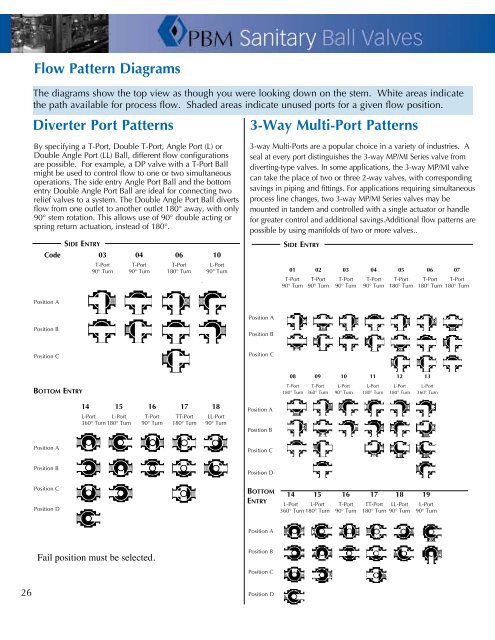
Flow Pattern Diagrams<br />
The diagrams show the top view as though you were looking down on the stem. White areas indicate<br />
the path available for process flow. Shaded areas indicate unused ports for a given flow position.<br />
Diverter Port Patterns<br />
3-Way Multi-Port Patterns<br />
By specifying a T-Port, Double T-Port, Angle Port (L) or<br />
Double Angle Port (LL) <strong>Ball</strong>, different flow configurations<br />
are possible. For example, a DP valve with a T-Port <strong>Ball</strong><br />
might be used to control flow to one or two simultaneous<br />
operations. The side entry Angle Port <strong>Ball</strong> and the bottom<br />
entry Double Angle Port <strong>Ball</strong> are ideal for connecting two<br />
relief valves to a system. The Double Angle Port <strong>Ball</strong> diverts<br />
flow from one outlet to another outlet 180° away, with only<br />
90° stem rotation. This allows use of 90° double acting or<br />
spring return actuation, instead of 180°.<br />
Side Entry<br />
Code 03 04 06 10<br />
T-Port T-Port T-Port L-Port<br />
90° Turn 90° Turn 180° Turn 90° Turn<br />
3-way Multi-Ports are a popular choice in a variety of industries. A<br />
seal at every port distinguishes the 3-way MP/MI Series valve from<br />
diverting-type valves. In some applications, the 3-way MP/MI valve<br />
can take the place of two or three 2-way valves, with corresponding<br />
savings in piping and fittings. For applications requiring simultaneous<br />
process line changes, two 3-way MP/MI Series valves may be<br />
mounted in tandem and controlled with a single actuator or handle<br />
for greater control and additional savings.Additional flow patterns are<br />
possible by using manifolds of two or more valves..<br />
Side Entry<br />
01 02 03 04 05 06 07<br />
T-Port T-Port T-Port T-Port T-Port T-Port T-Port<br />
90° Turn 90° Turn 90° Turn 90° Turn 180° Turn 180° Turn 180° Turn<br />
Position A<br />
Position A<br />
Position B<br />
Position B<br />
Position C<br />
Position C<br />
Bottom Entry<br />
08 09 10 11 12 13<br />
T-Port T-Port L-Port L-Port L-Port L-Port<br />
180° Turn 360° Turn 90° Turn 180° Turn 180° Turn 360° Turn<br />
14 15 16 17 18<br />
L-Port L-Port T-Port TT-Port LL-Port<br />
360° Turn 180° Turn 90° Turn 180° Turn 90° Turn<br />
Position A<br />
Position B<br />
Position A<br />
Position C<br />
Position B<br />
Position D<br />
Position C<br />
Position D<br />
Bottom<br />
Entry<br />
14 15 16 17 18 19<br />
L-Port L-Port T-Port TT-Port LL-Port L-Port<br />
360° Turn 180° Turn 90° Turn 180° Turn 90° Turn 90° Turn<br />
Position A<br />
Fail position must be selected.<br />
Position B<br />
Position C<br />
26<br />
Position D