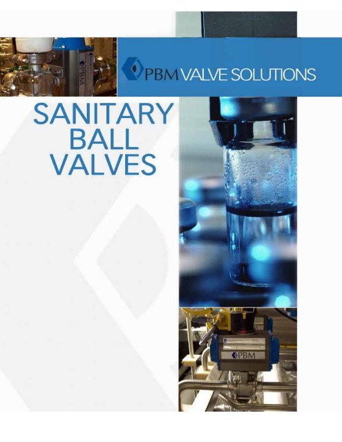
PBM Sanitary Ball Valves - Tri-Canada
PBM Sanitary Ball Valves - Tri-Canada
PBM Sanitary Ball Valves - Tri-Canada

You also want an ePaper? Increase the reach of your titles
YUMPU automatically turns print PDFs into web optimized ePapers that Google loves.
Adjust-O-Seal ® feature<br />
n <strong>PBM</strong> valves provide bidirectional upstream sealing. Seats are compressed<br />
tightly against the ball in the valve.<br />
n Body bolts can be tightened to compensate for normal seat wear without<br />
having to remove the valve from service.<br />
Competitor’s Design<br />
<strong>PBM</strong>’s Design<br />
Seals at<br />
downstream seat<br />
Seals at<br />
upstream seat<br />
Line pressure pushes ball downstream<br />
in the ball-closed position, providing<br />
sealing at the downstream seat. There<br />
is no adjustment to compensate for<br />
seat wear.<br />
Valve body bolts compress valve seats<br />
against the ball, providing bidirectional<br />
sealing at the upstream seat. To<br />
compensate for seat wear, body bolts<br />
can be slightly tightened to re-compress<br />
seats against ball.<br />
2<br />
<strong>PBM</strong> valves offer value over the life of<br />
the product with:<br />
n Fewer process interruptions<br />
n Longer Life<br />
n Clean/drain without process interruption<br />
n Improved product yields<br />
<strong>PBM</strong> also offers:<br />
n On-time delivery<br />
n Documentation<br />
n Solutions to tough applications<br />
This means on valves mounted vertically<br />
like <strong>PBM</strong>’s angle stem flush tank valve,<br />
the valve seats on the upstream seat,<br />
thus allowing the body to be purged and<br />
drained without process interruption.
Table of Contentss<br />
ITEM<br />
PAGE<br />
Features 2<br />
Ordering Information, Product Codes 4-5<br />
Materials of Construction, Alloys 6<br />
Seat & Seal Materials, O-ring Materials 6<br />
Allowable Working Pressures and Temperatures 7<br />
Cv Factors 8<br />
Polish Standards and Finishes 8<br />
Torque Values 9<br />
Testing 10<br />
Available Options 10-11<br />
Written Specifications 12-13<br />
DIMENSIONAL INFORMATION, MANUAL & AUTOMATED<br />
SI and CS Series Igenix ® 2-way, Forged and Cast * 14-17<br />
FI Series Igenix ® Flush Tank 18<br />
DI Series Igenix ® 3-Way Diverter 19<br />
Fire-Rated <strong>Valves</strong> 20-21<br />
Angle Stem Flush Tank 22-23<br />
MI Series Igenix ® 3, 4, & 5-Way Multi-Port 24-25<br />
Flow Patterns for 3, 4, and 5-way <strong>Valves</strong> 26-27<br />
S-, S2, & S3 Series Rising Stem Sampling <strong>Valves</strong> 28-29<br />
UNIQUE APPLICATION VALVES<br />
Igenix ® Trap <strong>Valves</strong> 30<br />
Cryogenic <strong>Ball</strong> Valve 31<br />
Self-Cleaning <strong>Ball</strong> Valve 32<br />
Spray <strong>Ball</strong> Valve 32<br />
Z-<strong>Ball</strong> TM - Zero Dead Leg <strong>Ball</strong> Valve 33<br />
Fabflex ® Manifolds, Process Break <strong>Valves</strong> 34<br />
3-Way Piggable 35<br />
Igenix ® Control <strong>Valves</strong>, V-ball 35<br />
Automation & Controls 36-37<br />
SANITARY CHECK VALVE USES NO SPRINGS OR GUIDES<br />
<strong>Sanitary</strong> Check <strong>Valves</strong>, Vertical and Horizontal 38-39<br />
REPRESENTATIVE LOCATIONS<br />
Representative Locations 40<br />
3
Ordering Information<br />
VALVE CONFIGURATION ORDERING INFORMATION - SANITARY<br />
Number(s) in parentheses indicate valve configuration part number position<br />
SANITARY<br />
PRODUCT<br />
(1-2)<br />
MATERIAL<br />
(3-4)<br />
SIZE - ”<br />
(5)<br />
SERIES<br />
(6)<br />
END CONNECTION<br />
(7-8)<br />
SEAT & SEAL / FILLER /<br />
O-RING 1 (9)<br />
CP Cryogenic C- Hastelloy ® C-276 A 1/4 1 AF A- Acme Bevel G TFM / - / Viton<br />
CS Clean Steam H- 316 Stainless B 3/8 4 MI F- Ext tube buttweld H S-TEF ® / - / Viton<br />
CT Clean Steam Trap HC Alloy 20 C 1/2 6 Firesafe Series 5 SI FX Weld X Clamp I S-TEF ® / VTFE / Viton<br />
DI Diverter Port HL 316L Stainless D 3/4 8 Igenix ® forged 1 G- Female CBI J TFM / VTFE / Viton<br />
DC Diverter CS HF F316L Forged E 1 9 Igenix ® cast 1 H- Male CBI K UHMWPE / - / Viton<br />
FI Flush Tank H2 317L Stainless G 1-1/2 I- Swagelok ® TS L UHMWPE / VTFE / Viton<br />
MI Multi-Port I- Inconel ® 600 H 2 J- CBQ M UHMWPE / UHMWPE /<br />
SI <strong>Sanitary</strong> 2-way P- AL6XN J 2-1/2 K- Cam Lock Viton<br />
T- Gr. 5 Titanium K 3 SL Swagelok ® Z TFM / - / EPR<br />
T2 Gr. 2 Titanium L 4 SM Swagelok ® 0 S-TEF ® / - / EPR<br />
T7 Gr. 7 Titanium M 6 Compression 1 S-TEF ® / VTFE / EPR<br />
Y- Hastelloy ® C-22 ® V- Socket weld - tube 2 TFM / VTFE / EPR<br />
5- Inconel ® 625 X- Hygenic - clamp 3 UHMWPE / - / EPR<br />
25 254SMO ® 6 Mo DIN / ISO -Z No end fittings 4 UHMWPE / VTFE / EPR<br />
22 Duplex 2205 1 8 5 UHMWPE / UHMWPE /<br />
76 Super Duplex 2 10 EPR<br />
32750 / 32760 3 15 6 2 PEEK ® / - / Viton<br />
55 Ferralium 255 4 20<br />
5 25<br />
6 32<br />
7 40<br />
8 50<br />
9 65<br />
V 80<br />
W 100<br />
Y 150<br />
Other connections<br />
available upon request.<br />
1 O-rings are used only in certain<br />
valve series (CS, CT,<br />
MI Series 4)<br />
2 Requires 17-4PH stem<br />
NOTE – All options are not available on all valve styles. Consult <strong>PBM</strong><br />
NOTE – For valves with 2 different end connections, use both end codes<br />
e.g. - FX = extended buttweld for tube by <strong>Tri</strong>-Clamp®<br />
NOTE - For valves with 2 different materials, use the 1 st position for body<br />
material and the 2 nd position for end fitting material<br />
TFM is standard for Series 4, 6, 8 & 9<br />
<strong>PBM</strong> may substitute TFM for RTFE at our discretion without notice<br />
TFM is a registered trademark of Dyneon - a 3M Company<br />
RTFE is standard for AF Series 1<br />
► ► ► ► ► ► ► E X A M P L E C O N F I G U R A T I O N ◄ ◄ ◄ ◄ ◄ ◄ ◄<br />
Number(s) in parentheses indicate valve configuration part number position<br />
Standard portion of part number Optional portion of part number 1,2<br />
(1 & 2) (3 & 4) (5) (6) (7 & 8) (9) (10 & 11) (12) (13 & 14) (15)<br />
PRODUCT MATERIAL SIZE SERIES END FITTING SEAT/SEAL<br />
FLOW PATTERN, PURGE<br />
PORTS OR BALL FLATS<br />
BALL / STEM OPERATOR POLISH<br />
SI HL H 9 X- G - - G 34 A<br />
SIHLH9X-G- -G34A is the code for a 2” Series 9 low Ferrite (
Ordering Information cont’d<br />
VALVE CONFIGURATION ORDERING INFORMATION - SANITARY - continued<br />
Number(s) in parentheses indicate valve configuration part number position<br />
FLOW PATTERN / TANK PAD / PURGE OPTIONS<br />
(10 & 11)<br />
BALL / STEM OPTIONS<br />
(12)<br />
OPERATOR OPTIONS<br />
(13 & 14)<br />
POLISH OPTIONS<br />
(15)<br />
For no flush tank, flow pattern or aseptic options, use “- -“ - Standard (no options) - - w/handle, w/actr prep - No polish<br />
For valves with flow patterns, enter 2-digit flow pattern # F Internal / external grounding 00 Stainless locking oval handle A 20Ra ID<br />
FLUSH TANK OPTIONS – POSITION 10 & 11 G 17-4PH stem 01 w/o handle B 32Ra OD<br />
- - Standard Flush Tank pad 02 w/o handle, w/actr prep C 20Ra ID / 32Ra OD<br />
01 No tank pad – w/o ship pad 03 w/handle, w/actr prep D 15Ra ID<br />
02 No tank pad – w/ship pad 04 Locking lever handle E 10Ra ID<br />
04 w/ 316L barstock pad 05 w/stainless oval handwheel F 20Ra ID after EP<br />
05 w/1” bolt-on tank pad 06 w/manual safety nut G 15Ra ID after EP<br />
06 w/1.5” bolt-on tank pad 07 w/45° handle H 10Ra ID after EP<br />
07 w/2” bolt-on tank pad 08 w/gear operator I 5Ra ID<br />
08 w/3” bolt-on tank pad 09 w/T-handle K 5Ra ID / 32Ra OD<br />
09 w/4” bolt-on tank pad 10 w/manual spring return handle L 20Ra ID / 32Ra OD<br />
10 w/6” bolt-on tank pad 11 w/fusible link spring return after EP<br />
11 w/8” bolt-on tank pad handle M EP ID & OD<br />
ASEPTIC VALVE OPTIONS – POSITION 10 12 w/vane actr for 80psig N 10Ra ID / 32Ra OD<br />
- No purge option(s) selected 1 13 w/N4 120VAC elect actr O 15Ra ID / 32Ra OD<br />
A (1) ½” <strong>Tri</strong>-Clamp® on center 90° from stem 14 w/N7 120VAC elect actr after EP<br />
B (1) ½” <strong>Tri</strong>-Clamp® on center opposite stem 15 w/square operating nut Q 15Ra ID / 32Ra OD<br />
C (1) ½” <strong>Tri</strong>-Clamp® upstream 90° from stem 16 w/locking handle & actr S 10Ra ID / 32Ra OD<br />
D (1) ½” <strong>Tri</strong>-Clamp® downstream opposite stem mount body after EP<br />
E (2) ½” <strong>Tri</strong>-Clamp® (1) on center 90° from stem & 17 1 w/4” ext locking oval<br />
(1) opposite stem handwheel POLISH NOTES<br />
F (2) ½” <strong>Tri</strong>-Clamp® (1) upstream 90° from stem & 18 1 w/4” ext locking lever handle<br />
(1) downstream opposite stem 20 DA80 psig actr<br />
G (1) ½” BWTE on center 90° from stem 21 DA80 psig actr & N4 LS<br />
H (1) ½” BWTE on center opposite stem 22 DA80 psig actr & N4 Sol<br />
I (1) ½” BWTE upstream 90° from stem 23 DA80 psig actr & N4 LS+Sol<br />
J (1) ½” BWTE downstream opposite stem 24 DA80 psig actr & N7 LS<br />
K (2) ½” BWTE on center (1) 90° from stem & 25 DA80 psig actr & N7 Sol<br />
(1) opposite stem 26 DA80 psig actr & N7 LS+Sol<br />
L (2) ½” BWTE (1) upstream 90° from stem & 27 DA60 psig actr<br />
(1) downstream opposite stem 28 DA60 psig actr & N4 LS<br />
M (1) ¼” FNPT on center 90° from stem 29 DA60 psig actr & N4 Sol<br />
N (1) ¼” FNPT on center opposite stem 30 DA60 psig actr & N4 LS+Sol<br />
O (1) ¼” FNPT upstream 90° from stem 31 DA60 psig actr & N7 LS<br />
P (1) ¼” FNPT downstream opposite stem 32 DA60 psig actr & N7 Sol<br />
Q (2) ¼” FNPT (1) on center 90° from stem & 33 DA60 psig actr & N7 LS+Sol<br />
(1) opposite stem 34 SR80 psig actr<br />
R (2) ¼” FNPT (1) upstream 90° from stem & 35 SR80 psig actr & N4 LS<br />
● On ID polished<br />
valves, the body, ball,<br />
seat retainer (if<br />
applicable) and end<br />
fittings are polished<br />
● On ID/OD polished<br />
valves, the body, ball,<br />
seat retainer (if<br />
applicable), and end<br />
fittings are polished<br />
● On ID+EP polished<br />
valves, the body, ball,<br />
seat retainer (if<br />
applicable), end<br />
fittings are polished.<br />
Stem is EP’d<br />
(1) downstream opposite stem 36 SR80 psig actr & N4 Sol<br />
BALL FLATS & HOLE OPTIONS – POSITION 11 37 SR80 psig actr & N4 LS+Sol LOX CLEANING (16)<br />
▼ Use these codes for 2-way & FT aseptic with std pad 38 SR80 psig actr & N7 LS L LOX cleaning per <strong>PBM</strong><br />
▼ Use these codes for aseptic FT w/ship pad 39 SR80 psig actr & N7 Sol procedure<br />
- U No flats or Holes 40 SR80 psig actr & N7 LS+Sol<br />
A K Flats closed downstream 41 SR60 psig actr<br />
B L Flats closed upstream 42 SR60 psig actr & N4 LS<br />
C M Flats open upstream 43 SR60 psig actr & N4 Sol<br />
D N Flats open downstream 44 SR60 psig actr & N4 LS+Sol<br />
E O Flats open upstream & downstream 45 SR60 psig actr & N7 LS<br />
F P Holes closed downstream 46 SR60 psig actr & N7 Sol<br />
G Q Holes closed upstream 47 SR60 psig actr & N7 LS+Sol<br />
H R Holes open upstream 51 2 DA80 psig actr & beacon<br />
I S Holes open downstream 52 2 DA60 psig actr & beacon<br />
J T Holes open upstream & downstream 53 2 SR80 psig actr & beacon<br />
V 2 Standard width slotted ball 54 2 SR60 psig actr & beacon<br />
W 3 30° V-ball 71 3 w/2” ext locking lever handle<br />
X 4 45° V-ball 72 3 w/2” ext locking oval<br />
Y 5 60° V-ball handwheel<br />
Z 6 90° V-ball<br />
1 7 120° V-ball N4 = NEMA 4<br />
8 9 Self-flushing ball N7 = NEMA 7<br />
LS = Limit Switch<br />
1 Use only if adding ball flats or drain holes Sol = Solenoid<br />
DA = Double Acting<br />
SR = Spring Return<br />
See note on<br />
previous page<br />
regarding positions<br />
(17-20)<br />
1<br />
2<br />
3<br />
<strong>Sanitary</strong> Series 1 AF,<br />
Series 6<br />
Add $95 list for beacon only<br />
on actuators<br />
<strong>Sanitary</strong> Series 8 & 9 only<br />
through 2”<br />
Price Book PL-US2009 April 6, 2009 Page 2 of 2<br />
5
Materials<br />
316L Stainless Steel<br />
Castings comply with A351, Alloy CF3M.<br />
Forgings (Series 8) comply with A182, Alloy F316L and 1.4404.<br />
Bar product complies with A479, Alloy S31603.<br />
Cast weld pads comply with SA 351, Alloy CF3M and wrought weld pads comply with SA 479, Alloy S31603.<br />
• Has a low (
Allowable Working Pressures (psig, barg)<br />
-20˚F to 100˚F/<br />
Non-Flanged<br />
Size<br />
Material<br />
-28.9˚C to 37.8˚C 300˚F/148.9˚C 450˚F/232.2˚C<br />
Valve Style/Series<br />
Inches/DIN psig barg psig barg psig barg<br />
SI, FI Series 6 316 SS/316L 3” (DN80) and under 720 49.6 620 42.7 540 37.2<br />
SI, CS, DI, DC 316 SS/316L All 600 41.4 455 31.4 397 27.4<br />
Series 8<br />
C-276 All 740 51.0 655 45.2 620 42.7<br />
316 SS/316L 1-1/2” (DN40) and smaller 900 62.1 770 53.1 680 46.9<br />
2” (DN50) thru 4” (DN100) 720 49.6 620 42.7 540 37.2<br />
SI, CS, DI, DC<br />
6” (DN150) 375 25.9 320 22.1 280 19.3<br />
Series 9<br />
C-276 4” (DN100) and smaller 600 4.14 510 35.2 450 31.0<br />
6” (DN150) 375 25.9 320 22.1 280 19.3<br />
MI<br />
All Series 4<br />
AF Series 1<br />
AF Series 3<br />
FI, FC<br />
Series 8 & 9<br />
Notes:<br />
316 SS/316L 3/4” (DN20) and smaller 900 62.1 770 53.1 680 46.9<br />
316 SS/316L 1” (DN25) thru 4” (DN100) 720 49.6 620 42.7 540 37.2<br />
316 SS/316L 6” (DN150) 275 19.0 205 14.1 195 13.4<br />
C-276 3/4” (DN20) and smaller 900 62.1 770 53.1 680 46.9<br />
C-276 2” (DN50) thru 4” (DN100) 720 49.6 620 42.7 540 37.2<br />
C-276 6” (DN150) 275 19.0 205 14.1 195 13.4<br />
316 SS/316L 1-1/2” (DN40) and smaller 900 62.1 770 53.1 680 46.9<br />
316 SS/316L 2” (DN50), 4” (DN100) 550 37.9 540 37.2 525 36.2<br />
316 SS/316L 3” (DN80) 625 43.1 610 42.1 600 41.4<br />
316 SS/316L 6” (DN150) 375 25.9 365 25.2 360 24.8<br />
C-276 1-1/2” (DN40) and smaller 600 41.4 520 35.9 475 32.8<br />
C-276 2” (DN50), 4” (DN100) 550 37.9 540 37.2 525 36.2<br />
C-276 3” (DN80) 600 41.4 520 35.9 475 32.8<br />
C-276 6” (DN150) 375 25.9 320 22.1 280 19.3<br />
316 SS/316L 1-1/2” (DN40) and smaller 720 49.6 620 42.7 540 37.2<br />
316 SS/316L 2” (DN50), 4” (DN100) 550 37.9 540 37.2 525 36.2<br />
316 SS/316L 3” (DN80) 625 43.1 610 42.1 600 41.4<br />
316 SS/316L 6” (DN150) 375 25.9 365 25.2 360 24.8<br />
316 SS/316L 4” (DN100) and smaller 600 4.14 510 35.2 440 30.3<br />
316 SS/316L 6” (DN150) 375 25.9 320 22.1 280 19.3<br />
C-276 4” (DN100) and smaller 600 4.14 510 35.2 440 30.3<br />
C-276 6” (DN150) 375 25.9 320 22.1 280 19.3<br />
1. Bronze, 316 SS and C-276 retain their CWP below minus 20˚F.<br />
2. All valves rated for full vacuum.<br />
3. <strong>Sanitary</strong> clamps and gaskets may limit pressure ratings to less than shown above.<br />
<strong>Valves</strong> 1-1/2-Inch and Smaller<br />
2-Inch to 3-Inch<br />
1000<br />
800<br />
900<br />
700<br />
800<br />
600<br />
700<br />
600<br />
500<br />
400<br />
300<br />
200<br />
100<br />
Pressure (psig)<br />
UHMWPE<br />
VTFE<br />
RTFE/TFM<br />
SS/TFE<br />
PEEK<br />
Pressure (psig)<br />
500<br />
400<br />
300<br />
200<br />
100<br />
UHMWPE<br />
VTFE<br />
RTFE/TFM<br />
SS/TFE<br />
PEEK<br />
0<br />
0 50 100 150 200 250 300 350 400 450 500<br />
Temperature (F)<br />
Seat & Seal<br />
Temperature<br />
and Pressure<br />
Charts<br />
4 and 6-Inch<br />
0<br />
0 100 200 300 400 500 600<br />
600<br />
500<br />
400<br />
300<br />
200<br />
Pressure (psig)<br />
Temperature (F)<br />
UHMWPE<br />
VTFE<br />
RTFE/TFM<br />
SS/TFE<br />
PEEK<br />
100<br />
0<br />
0 50 100 150 175 200 250 300 350 400 450 500<br />
Temperature (F)<br />
7
Cv Values (gpm)<br />
VALVE<br />
SIZE<br />
2-WAY<br />
SERIES 8 & 9<br />
FLUSH TANK<br />
DIVERTER PORT<br />
SERIES 8 & 9<br />
MULTI-PORT<br />
SERIES 4<br />
CT<br />
<strong>Valves</strong><br />
SI, CS AF FI DI SERIES, X-ENDS MI SERIES 4, X-ENDS Trap Position<br />
End Connection X-END X-END T-PORT T-PORT<br />
Series<br />
L-PORT L-PORT<br />
F- X- Series 1 Series 8 & 9 Straight Branch Straight Branch 8 & 9<br />
1/2” 6.5 8.0 8.9 4.0 4.7 3.0 4.7 3.0 4.0 0.41<br />
3/4” 23 28 34 12 15 9.0 15 9.0 12 0.72<br />
1” 55 65 63 62 25 29 18 29 18 25 0.96<br />
1 1/2” 160 193 150 175 68 81 49 81 49 68 2.8<br />
2” 365 420 280 480 133 160 92 160 92 118 2.7<br />
2 1/2” 700 800<br />
3” 900 1.040 505 870 324 390 233 390 233 278 5.4<br />
4” 1,800 2,080 690 1,550 590 715 430 715 430 510 15<br />
6” 4,200 5,000 1,430 3,750 1,450 1,750 1,040 1,750 1,040 1,160<br />
* F- (extended buttweld) end<br />
* X- (Hygienic) end<br />
ID Surface Finish. Ra Readings for <strong>Valves</strong> per ASME BPE<br />
(Bioprocessing Equipment)<br />
<strong>PBM</strong>’s IGENIX ® forged valves have a standard internal polish of 20 R a Max/0.50 µm or better.<br />
Ra max.<br />
Surface<br />
<strong>PBM</strong> Polish Code µ-in. µm<br />
Description<br />
Mechanical Polish<br />
SF 1 A 20 0.51<br />
SF 2 A 25 0.64<br />
SF 3 - 30 0.76<br />
Mechanical polish and electropolish<br />
SF 4 G 15 0.38<br />
SF 5 F 20 0.51<br />
SF 6 F 25 0.64<br />
Default Polish:<br />
Series 8 - 20 Ra<br />
Series 9 - 30 Ra<br />
O-Ring and Seat Compliancy<br />
Compliancy<br />
Material FDA USP Class VI 3A<br />
O-ring* E3609-70 (EPR) Yes Yes No<br />
Seat Virgin TFM TM Yes Yes Yes<br />
*O-rings used in “Clean Steam” Series CS, CT, FC, DC.<br />
8
Stem Torque<br />
Valve<br />
Style/<br />
Series<br />
Series<br />
6<br />
Firesafe<br />
All<br />
Series *<br />
& 9<br />
2-Way<br />
and<br />
3-Way<br />
AF<br />
Series 1<br />
and<br />
Series 3<br />
CP<br />
Series 5<br />
MI<br />
Series 4<br />
Notes:<br />
Valve<br />
Size<br />
(in.)<br />
As built<br />
Torque<br />
0<br />
psig<br />
0<br />
barg<br />
100<br />
psig<br />
6.9<br />
barg<br />
TFM TM and VTFE Seats - Differential Pressure across Seats<br />
200<br />
psig<br />
13.8<br />
barg<br />
300<br />
psig<br />
in.-lb. N-m in.-lb. N-m in.-lb. N-m in.-lb. N-m in.-lb. N-m in.-lb. N-m in.-lb. N-m in.-lb. N-m in.-lb. N-m<br />
1/4 32 3.6 64 7.2 64 7.2 64 7.2 64 7.2 64 7.2 64 7.2 64 7.2 64 7.2<br />
1/2 32 3.6 64 7.2 64 7.2 64 7.2 64 7.2 64 7.2 64 7.2 64 7.2 64 7.2<br />
3/4 40 4.5 80 9.0 80 9.0 80 9.0 80 9.0 80 9.0 96 10.8 112 10.8 128 12.7<br />
20.7<br />
barg<br />
400<br />
psig<br />
27.6<br />
barg<br />
500<br />
psig<br />
34.5<br />
barg<br />
1 58 6.6 116 13.1 116 13.1 116 13.1 150 16.9 185 20.9 220 24.9 trun.<br />
1-1/2 154 17.4 308 34.8 308 34.8 440 49.7 580 65.5 715 80.8 trun. trun.<br />
2 182 20.6 364 41.1 364 41.1 635 71.7 910 102.8 1,180 133.3 trun. trun.<br />
2-1/2 288 32.5 576 65.1 576 65.1 1,200 135.6 1,600 180.8 trun.<br />
3 430 48.6 860 97.2 860 97.2 1,560 176.3 trun. trun.<br />
4 787 88.9 1,570 177.4 2,650 299.4 trun. trun.<br />
6 1,920 217.0 3,840 433.9 7,100 802.3 Use trunnion above 75 psid.<br />
1/4 25 2.8 50 5.7 50 5.7 50 5.7 50 5.7 50 5.7 50 5.7 50 5.7 50 5.7<br />
1/2 25 2.8 50 5.7 50 5.7 50 5.7 50 5.7 50 5.7 50 5.7 50 5.7 50 5.7<br />
3/4 30 3.4 60 6.8 60 6.8 60 6.8 60 6.8 60 6.8 60 6.8 60 6.8 80 9.0<br />
1 50 5.7 100 11.3 100 11.3 100 11.3 130 14.7 160 18.1 220 24.9 trun. trun.<br />
1-1/2 132 14.9 264 29.8 264 29.8 375 42.4 500 56.5 600 67.8 trun. trun.<br />
2 182 20.6 364 41.10 364 41.1 635 71.8 910 102.8 1,180 133.3 trun. trun.<br />
2-1/2 288 32.5 576 65.1 576 65.1 1,200 136 1,600 181 trun trun.<br />
3 430 49 860 97.2 860 97.2 1,560 176 trun. trun.<br />
4 672 76 1,340 151 2,250 254 trun. trun.<br />
6 1,920 217 3,840 434 7,100 802 Use trunnion above 75 psid.<br />
1 58 6.6 116 13.1 116 13.1 116 13.1 150 17.0 185 20.9 220 24.9 255 28.8 288 32.5<br />
1-1/2 132 14.9 264 29.8 264 29.8 375 42.4 500 56.5 600 67.8 725 81.9 850 96.1 950 107<br />
2 154 17.4 308 34.8 308 34.8 440 49.7 580 65.5 715 80.8 850 96.1<br />
3 336 38.0 675 76.3 675 76.3 1,400 158 1,900 215 2,400 271 2,900 328 3,400 384<br />
4 432 49 860 97.2 860 97.2 1,560 176 2,050 232 2,540 287 3,030 342<br />
6 1,056 119 2,100 237 3,950 446<br />
1/2 35 4.0 190 21.5 190 21.5 190 21.5 190 21.5<br />
3/4 44 5.0 270 30.5 270 30.5 270 30.5 270 30.5<br />
1 64 7.2 400 45.2 400 45.2 400 45.2 400 45.2<br />
1-1/2 169 19.1 900 102 900 102 900 102 900 102<br />
2 200 22.6 1400 158 1400 158 1400 158 1400 158<br />
1/2 77 8.7 144 16.3 144 16.3 144 16.3 144 16.3 144 16.3 144 16.3 144 16.3 144 16.3<br />
3/4 77 8.7 144 16.3 144 16.3 144 16.3 144 16.3 144 16.3 144 16.3 144 16.3 144 16.3<br />
1 192 21.7 385 43.5 385 43.5 385 43.5 385 43.5 385 43.5 385 43.5 440 49.7 trun. trun.<br />
1-1/4 192 21.7 385 43.5 385 43.5 385 43.5 385 43.5 385 43.5 385 43.5 440 49.7 trun. trun.<br />
1-1/2 384 43.4 770 87 770 87 770 87 940 106.2 trun. trun.<br />
2 432 48.8 865 97.7 865 97.7 865 97.7 1,200 135.6 trun. trun.<br />
3 864 97.6 1,730 195.5 1,730 195.5 trun. trun.<br />
4 1,920 216.9 3,840 433.9 3,840 433.9 trun. trun.<br />
6 3,000 339.0 6,000 678.0 8,800 994.4 Use trunnion above 75 psid.<br />
1. For valves with RTFE or UHMWPE seats, multiply the above values by 1.25<br />
2. For valves which have S-TEF ® or Kynar ® seats, multiply the above values by 1.56.<br />
3. For valves with PEEK ® seats, multiply the above values by 1.7.<br />
4. Where trunnion is indicated, <strong>PBM</strong> recommends trunnion mounting the ball to avoid excessive seat loads and stem torques.<br />
5. For Series 8 & 9 CS 2-1/2” & larger valves in steam service and having RTFE seats, multiply minimum TFM/VTFE actuator torques by 1.56.<br />
6. To convert in-lbs. torques to N-m, multiply by 0.113.<br />
600<br />
psig<br />
41.4<br />
barg<br />
700<br />
psig<br />
48.3<br />
barg<br />
9
Testing<br />
n Vacuum Testing<br />
n Cycle Testing<br />
n Shock and Vibration<br />
n Seismic<br />
n Hydrostatic<br />
n Material Test Reports<br />
- Physical testing<br />
- Chemical testing<br />
Options<br />
n Cryogenic<br />
n V-<strong>Ball</strong>s for Flow Control<br />
n Manual Spring Return Handles n Internal & External Grounding<br />
n LOX (Cleaned for Oxygen Service) n Mechanical & Electro-Polishing<br />
n Body Cavity Fillers<br />
n Direct Mount Actuation<br />
n Steam Seats (Encapsulated)<br />
n Positioners<br />
n Purge Ports (SIP/CIP)<br />
n Fieldbus, AS-i, DeviceNet<br />
n Fire Rated, API 607<br />
n <strong>Ball</strong> Flats and Purge Holes<br />
n Dribble Control Units<br />
n Locking Handle<br />
n High Alloys<br />
n Extended Locking Handle<br />
n Fabflex® Manifolds<br />
n Cylindrical Radius Weld Pads<br />
n Self Cleaning Flushable <strong>Ball</strong><br />
Steam <strong>Valves</strong><br />
10
Options<br />
Cylindrical Radius Pad<br />
Direct Mount Actuation<br />
Cavity Fillers<br />
Purge Ports, Milled Flats and<br />
Purge Holes<br />
Locking Handle<br />
11
Written Specifications<br />
FORGED VALVES<br />
SI-Series 8 (1/2” through 4”, DIN 11850 DN 8 through DN 100, ISO 1127 DN 8 through DN 80) <strong>PBM</strong>’s Forged IGENIX® <strong>Sanitary</strong><br />
Series 8, “True Bore ® ” ball valve with port through ball, seats, and end fittings same as ID of tubing. Forged 316L stainless steel body<br />
and end fittings per ASTM A182F316L / DIN 1.4404, wrought or forged 316L ball and stem, less than 1% ferrite, three piece swing-out<br />
valve design. Seats and seals shall be white TFM. Seats shall provide both upstream and downstream bubbletight seal and be<br />
adjustable for inline wear. Stem packing shall be live loaded white TFM and S-TEF ® material. End fittings shall match to tubing<br />
connections. Orbital weld end fittings should have wall thickness to match connecting tubing and have a controlled sulfur content of<br />
0.005% through 0.017%. <strong>Valves</strong> shall not require disassembly for welding. Body bolts and nuts shall be 18-8 stainless steel. Interior<br />
surfaces shall be 20 RA or better with optional electropolish and finer mechanical finishes. Valve shall have integral mounting pad to<br />
allow adaptation to ISO 5211 for direct mount automation. All materials are FDA and USP23 Class VI compliant. Maximum working<br />
pressure to be 600 PSIG, but is limited based on valve size, valve material and end fitting type. <strong>Valves</strong> are full vacuum. To add<br />
automation and controls, see section “Automation and controls”.<br />
<strong>PBM</strong> Model number SI (material)(size)8(end connection);<br />
CS-Series 8 (1/2” through 4”, DIN 11850 DN 8 through DN 100, ISO 1127 DN 8 through DN 80) <strong>PBM</strong>’s IGENIX® Clean Steam Series<br />
8. Same Specification as SI-Series 8 above. Add text “Seats and seals shall be white TFM with FDA approved EPR O-ring energizer.<br />
Seats shall have stainless steel encapsulation on ID. Body seal shall be FDA approved EPR o-rings with white TFM back up seal.<br />
Optional 300 Series s/s 4” stem extension with locking lever handle for 4” thick installation.<br />
<strong>PBM</strong> Model number CS (material)(size)8(end connection); Trap valve model number CT (material)(size)8(end connection)<br />
CAST VALVES<br />
SI-Series 9 (1/2” through 6”, DIN 11850 DN 8 through DN 150, ISO 1127 DN 8 through DN 100) <strong>PBM</strong>’s IGENIX ® <strong>Sanitary</strong> Series 9<br />
“True Bore ® ” ball valve with port through ball, seats, and end fittings same as ID of tubing. Type (316 L stainless steel with less than 2%<br />
ferrite, , Hastelloy ® C-276 or C22 ® , or other) body, ball, stem, and end fittings, three piece swing-out valve design. Seats and seals shall<br />
be combined “cartridge” and be white TFM. Seats shall provide both upstream and downstream bubbletight seal and be adjustable for<br />
in-line wear. Stem packing shall be live loaded white TFM or S-TEF ® material. End fittings shall match to tubing connections. Orbital<br />
weld end fittings should have wall thickness to match connecting tubing and have a controlled sulfur content of .005% through .017%.<br />
<strong>Valves</strong> shall not require disassembly for welding. Body bolts and nuts shall be 18-8 stainless steel. I.D. and O.D. surface finish shall be<br />
the same as specified for tubing. Maximum working pressure to be 900 PSIG, but is limited based on valve size, valve material and end<br />
fitting type. <strong>Valves</strong> are full vacuum. <strong>Valves</strong> shall be non-fire rated design unless otherwise specified. To add automation and controls,<br />
see section “Automation and controls”.<br />
<strong>PBM</strong> Model number SI (material)(size)9(end connection)<br />
CS-Series 9 (1/2” through 6”): <strong>PBM</strong>’s IGENIX® Clean Steam Series 9, Same specification as SI (cast) above. Add text “Seats shall be<br />
white TFM with FDA approved EPR O-ring energizer. Seats shall have stainless steel encapsulation on ID. Optional 300 Series s/s<br />
stem extensions for thick insulation.<br />
<strong>PBM</strong> Model number CS (material)(size)9(end connection)<br />
CT-Series 8 (forged) or Series 9 (cast): <strong>PBM</strong>’s IGENIX ® Clean Steam Series 8 or 9. Same specification as CS forged or cast above.<br />
Add text. ”Valve shall have a dual chamber seat design to allow for a 1/2” <strong>Tri</strong>-Clamp® steam drain purge port positioned in the valve<br />
body to facilitate drainage of the body cavity to the trap. <strong>Ball</strong> shall have 2 steam purge holes to allow steam condensate to flow past<br />
seats in closed position to trap. Stem packing shall be live loaded white TFM and S-TEF ® . Provide a 90 deg 2-position or 180deg<br />
3-position stainless steel handle with blue vinyl grip for closed/open, and/or trap isolated valve positions. A locking handle position<br />
mechanism shall be available if required.<br />
<strong>PBM</strong> Model number CT (material)(size)8 or 9(end connection)<br />
FI & AF SERIES<br />
FI-Series 9 (1/2” through 6”): Flush tank bottom ball valve: <strong>PBM</strong>’s IGENIX® <strong>Sanitary</strong> Series 9 Flush Tank <strong>Ball</strong> Valve. “True Bore®”<br />
flush bottom tank ball valve with port through ball, seats, weld pad, and end fitting same as ID of tubing. Type 316L stainless steel<br />
with less than 2% ferrite, Hastelloy ® C-276, Carbon Steel, Hastelloy ® C-22 ® , or other materials for body, ball, stem, weld pad, and end<br />
fitting, three piece swing-out valve design. Seats and seals shall be white TFM. Seats shall provide both upstream and downstream<br />
bubbletight seal and be adjustable for in-line wear. Stem packing shall be live loaded white TFM and/or S-TEF ® material. End<br />
fitting shall match to tubing connections. Orbital weld end fittings should have wall thickness to match connecting tubing and have a<br />
controlled sulfur content of .005% through .017%. <strong>Valves</strong> shall not require disassembly for welding. Body bolts and nuts shall be 18-8<br />
stainless steel. I.D. and O.D. surface finish shall be the same as specified for tubing. Maximum working pressure to be 600 PSIG, but is<br />
limited based on valve size, valve material and end fitting type. <strong>Valves</strong> are full vacuum.<br />
<strong>PBM</strong> Model number FI(material)-(size)9(end connection)<br />
12
FC-Series 9 (1/2” through 6”): <strong>PBM</strong>’s IGENIX® Clean Steam Series 9, Same specification as SI (cast) above. Add text “Seats shall be<br />
white TFM with FDA approved EPR O-ring energizer. Seats shall have stainless steel encapsulation on ID. Optional 300 Series s/s stem<br />
extensions for thick insulation.<br />
<strong>PBM</strong> Model number FC (material)(size)9(end connection)<br />
AF Series 1: Angle stem flush tank bottom ball valve; Body, ball, stem, and end fitting material shall be (316 stainless steel, Hastelloy ®<br />
C276, Hastelloy ® C-22 ® , or other). Weld pad shall be 316L grade stainless steel (or other) material (specify). Valve shall be two-piece<br />
design. Seats and seals shall be VTFE material and provide both upstream and downstream bubbletight seal and be adjustable for inline<br />
wear. Stem packing shall be live loaded VTFE material. For manual valves, handle shall be 300 series stainless steel. Body bolts and nuts<br />
shall be 18-8 stainless steel. Maximum working pressure is 900 psig, but is limited based on valve size, valve material and end fitting<br />
type. <strong>Valves</strong> are full vacuum. <strong>Valves</strong> shall be non-firesafe design unless otherwise specified. For fire rated valves to API 607 Ed 4, sizes<br />
1” – 6”, designate Series 3. To add automation and controls, see last section.<br />
<strong>PBM</strong> Model number AF(material)-(size)1(end connection)<br />
FIRE RATED<br />
Fire Rated 2-way, SI- and FI- 1/2” to 3”, AF 1” to 6”. Add text: Valve design shall be tested and comply with criteria set forth in<br />
API-607 edition 4. Valve body bolts shall be fully encapsulated. Body seals shall be graphite material isolated from product stream under<br />
normal operation conditions by o-ring seals. Upon sublimation of seat and seal material in the event of a fire condition, a metal back up<br />
seat shall seal the valve at leakage rates in accordance with API-607 Ed. 4.<br />
Model Number: Same as above, except Series “9” Changes to “6”, Series “1” changes to “3”.<br />
D SERIES<br />
DI-Series 9, Three-way diverter port ball valve. “True Bore ® ” diverter port ball valve with port through ball, seats and end fitting same as<br />
ID of tubing. Type (316L stainless steel with less than 2% ferrite, Hastelloy ® C-276 or C22 ® , or other) body, ball, stem, and end fittings,<br />
three piece swing-out valve design. Seats and seals shall be combined “cartridge” and be white TFM. Seats shall provide both upstream<br />
and downstream bubbletight seal and be adjustable for in-line wear. Stem packing shall be live loaded white TFM or S-TEF ® material.<br />
End fittings shall match to tubing connections. Orbital weld end fittings should have wall thickness to match connecting tubing and have<br />
a controlled sulfur content of .005% through .017%. <strong>Valves</strong> shall not require disassembly for welding. Body bolts and nuts shall be 18-8<br />
stainless steel. I.D. and O.D. surface finish shall be the same as specified for tubing. Maximum working pressure to be 900 PSIG, but is<br />
limited based on valve size, valve material and end fitting type. <strong>Valves</strong> are full vacuum. <strong>Valves</strong> shall be non-fire rated design. To add<br />
automation and controls, see section “Automation and controls”.<br />
<strong>PBM</strong> Model number DI(material)-(size)9(end connection) – (flow pattern)<br />
DC-Series 9 (1/2” through 6”): <strong>PBM</strong>’s IGENIX® Clean Steam Series 9, Same specification as SI (cast) above. Add text “Seats shall be<br />
white TFM with FDA approved EPR O-ring energizer. Seats shall have stainless steel encapsulation on ID. Optional 300 Series s/s stem<br />
extensions for thick insulation.<br />
<strong>PBM</strong> Model number CS (material)(size)9(end connection)<br />
M SERIES<br />
MI-Series 4: Three, four, or five way multi-port ball valve; Body, ball, stem, and end fitting material shall be (316L stainless steel,<br />
Hastelloy ® C-276, or other). Valve shall have 4 or 5 TFM-PTFE Seats and seals and provide bubbletight seal and be adjustable for inline<br />
wear. Stem packing shall be live loaded TFM-PTFE material. For manual valves, handle shall be 300 series stainless steel. Body bolts<br />
and nuts shall be 18-8 stainless steel. Maximum working pressure to be 900 psig, but is limited based on valve size, valve material and<br />
end fitting type. <strong>Valves</strong> are full vacuum. Specify <strong>PBM</strong> flow pattern for 3,4,or 5-way valve. To add automation and controls, see section<br />
“Automation and controls”.<br />
<strong>PBM</strong> Model number MI(material)-(size)4(end connection)-(flow pattern)<br />
AUTOMATION AND ConTrolS<br />
<strong>PBM</strong>’s Direct Mount Automated <strong>Ball</strong> <strong>Valves</strong>, <strong>Valves</strong> as specified in “Manual <strong>Valves</strong>” section with addition of a “Direct<br />
Mount” double acting or spring return pneumatic actuator. Actuator shall be of the double opposing piston, rack and pinion design with<br />
bi-directional pinion travel stops and hard anodized aluminum oxide body with co-deposited fluoropolymer. End caps to be polyester<br />
powder coated with 300 series stainless steel fasteners. Mounting bracket shall be stainless steel and valve stem shall insert directly into<br />
actuator drive adapter. Actuator shall be sized utilizing a 100% safety factor. Specify supply air pressure at actuator (60 or 80 psig). <strong>PBM</strong><br />
Model Number “PA”<br />
<strong>PBM</strong>’s electric actuators, limit switches, positioners, solenoids, and field bus accessories. Specify according to all statutory and regulatory<br />
requirements. Include Nema rating requirements and electrical current.<br />
RISING STEM SAMPLING VALVES<br />
S-, S2, S3 Rising Stem Sampling <strong>Valves</strong>: Body and stem shall be wrought or cast 316L stainless steel, TFM seat and elastomer<br />
(Viton, EPR, or EPDM) o-ring seal. Handle knob shall be nylon 6/6. Bore is 1/4”, with available inlets and outlets 90 degree or in-line in<br />
sizes 1/2” through 2”.<br />
<strong>PBM</strong> Model number S- (sanitary wrought split-body), S2 (unibody cast sampling), or S3 (inline version)<br />
13
Igenix® Cast Series 9 or Forged Series 8<br />
2-Way <strong>Sanitary</strong> and Clean Steam <strong>Valves</strong><br />
U.S. Dimensioned valves in inches<br />
Valve<br />
Size<br />
Size Code I.D. Port A1 A2 B1 B2 C D E F G H<br />
1/2”** C 0.37 3.50 5.50 1.75 2.75 1.70 0.75 2.03 4.00 1.50 1.50 1.1<br />
3/4”** D 0.62 4.00 6.00 2.00 3.00 1.86 0.85 2.19 4.00 1.68 1.50 1.4<br />
1”** E 0.87 4.50 6.50 2.25 3.25 2.40 1.09 2.97 4.15 2.18 1.50 2.7<br />
1-1/2”** G 1.37 5.50 7.50 2.75 3.75 3.89 1.68 4.91 8.81 3.31 1.50 8.9<br />
Approx.<br />
Wgt (lbs)<br />
2”** H 1.87 6.25 8.00 3.12 4.00 4.67 2.15 4.41 8.06 4.30 1.75 15.0<br />
2-1/2”* J 2.37 8.00 11.50 4.00 5.75 6.51 2.79 6.46 12.06 5.58 2.31 36.0<br />
3”** K 2.87 8.00 10.50 4.00 5.25 6.76 2.78 6.71 12.06 5.58 1.75 33.0<br />
4”** L 3.84 10.00 13.00 5.00 6.50 7.53 3.66 7.48 12.06 7.33 2.00 67.0<br />
6”* M 5.78 13.00 17.00 6.50 8.50 12.14 6.18 CF CF 12.37 2.50 164.0<br />
*Cast Only<br />
**Wrought Material or Cast<br />
ISO 1127 Dimensioned valves in mm<br />
Valve<br />
Size<br />
Size<br />
Code<br />
I.D.<br />
Port<br />
Tube<br />
O.D.<br />
Tube<br />
wall<br />
Forged valves are < 1% ferrite.<br />
Cast valves are < 2% ferrite.<br />
Tube<br />
Series A2 B2 C D E F G H<br />
DN 8 1 10.3 13.5 1.6 1 140 70 44 19 52 103 38 38 0.5<br />
DN 10 2 14.0 17.2 1.6 1 150 75 48 22 56 103 38 38 0.6<br />
DN 15 3 18.1 21.3 1.6 1 165 83 62 28 76 131 55 38 1.2<br />
DN 20 4 23.7 26.9 1.6 1 190 95 100 43 126 226 84 38 4.0<br />
DN 25 5 29.7 33.7 2.0 1 190 95 100 43 126 226 84 38 4.0<br />
DN 32 6 38.4 42.4 2.0 1 190 95 100 43 126 226 84 38 4.0<br />
DN 40 7 44.3 48.3 2.0 1 200 100 120 55 113 208 109 42 6.8<br />
Approx.<br />
Wgt. (kg.)<br />
DIN 11850 Dimensioned valves in mm<br />
Valve<br />
Size<br />
Size<br />
Code<br />
I.D.<br />
Port<br />
Tube<br />
O.D.<br />
Tube<br />
wall<br />
Tube<br />
Series<br />
A2 B2 C D E F G H<br />
DN 8 1 8 10 1.0 1 140 70 52 19 52 102 38 38 0.5<br />
DN 10 2 10 13 1.5 2 140 70 52 19 52 102 42 38 0.5<br />
DN 15 3 16 19 1.5 2 152 76 56 22 76 105 42 38 1.2<br />
DN 20 4 20 23 1.5 2 165 83 76 28 76 105 55 38 1.2<br />
DN 25 5 26 29 1.5 2 190 95 100 43 125 224 84 38 4.0<br />
DN 32 6 32 35 1.5 2 190 95 100 43 125 224 84 38 4.0<br />
DN 40 7 38 41 1.5 2 190 95 100 43 125 224 84 38 4.0<br />
Approx.<br />
Wgt (kg.)<br />
DN 50 8 50 53 1.5 2 200 100 120 55 119 205 109 42 6.8<br />
F<br />
F<br />
C<br />
E<br />
C<br />
E<br />
D<br />
14<br />
A2<br />
B2<br />
B1<br />
A1<br />
G
Igenix® Cast Series 9 or Forged Series 8 Extended Locking Lever Handle<br />
Extended Locking Lever Handle<br />
Valve Size A B - 2” C B - 4” E<br />
US DN ID ISO inches mm inches mm inches mm inches mm inches mm<br />
1/2” 8, 10 8 5.09 129 4.00 102 2.50 64 6.00 152 0.31 8<br />
3/4” - 10 5.09 129 4.14 105 2.50 64 6.14 156 0.31 8<br />
1” 15,20 15 5.09 129 5.44 138 3.50 89 7.44 189 0.31 8<br />
1-1/2” 25,32,40 20,25,32 8.00 203 7.46 189 3.75 95 9.46 240 0.38 10<br />
2” 50 40 8.00 203 7.74 197 4.30 109 9.74 247 0.38 10<br />
2-1/2” - - 12.10 307 9.36 238 5.58 142 11.36 289 0.38 10<br />
3” - - 12.40 315 9.61 244 5.58 142 11.61 295 0.38 10<br />
4” - - 12.40 315 10.38 264 7.33 186 12.38 314 0.38 10<br />
A<br />
MANUAL VALVES W/ TUBING ENDS (inches)<br />
C<br />
E<br />
Valve<br />
Size<br />
Tube<br />
OD<br />
Insulation<br />
max with<br />
no<br />
extension<br />
Insulation<br />
max with<br />
2”<br />
extension<br />
Insulation<br />
max with<br />
4”<br />
extension<br />
1/2” 0.500 0.76 2.68 4.68<br />
Note: 2” extension standard on 1/2” - 2”. 4” extension standard on 2-1/2” - 4”..<br />
B<br />
3/4” 0.750 0.79 2.72 4.72<br />
1” 1.000 1.45 3.88 5.88<br />
1-1/2” 1.500 3.10 5.57 7.57<br />
2” 2.000 2.31 5.60 7.60<br />
2-1/2” 2.500 4.00 6.88 8.88<br />
3” 3.000 4.08 6.88 8.88<br />
4” 4.000 4.35 7.12 9.12<br />
Maximum insulation dimensions shown allow for 3/4” of clearance<br />
between outside of insulation and bottom of handle.<br />
Locking Handle<br />
Valve Size A B C<br />
US DIN ISO inches mm inches mm inches mm<br />
1/2” 8, 10 8 4.00 102 2.03 52 1.55 39<br />
3/4” - 10 4.00 102 2.19 56 1.55 39<br />
1” 15,20 15 5.10 130 2.97 75 1.64 42<br />
1-1/2” 25,32,40 20,25,32 8.80 224 4.91 125 2.57 65<br />
2” 50 40 8.10 206 4.41 112 2.57 65<br />
2-1/2” - - 12.40 315 6.46 164 3.84 98<br />
3” - - 12.40 315 6.75 171 3.84 98<br />
4” - - 12.40 315 7.75 197 3.84 98<br />
C<br />
A<br />
B<br />
15
Igenix® Cast Series 9 or Forged Series 8 Actuated<br />
Spring Return SR Series 80 PSI/5.5 barg Supply Air, VTFE or TFM TM Seats<br />
Valve Size Model A B C D E F (Flush Tank only)<br />
US DIN ISO<br />
Number<br />
PAVBL inches mm inches mm inches mm inches mm inches inches mm<br />
1/2” 8, 10 8 453S--0052 5.49 139 2.80 71 4.97 126 1.61 41 1/8 NPT -0.13 -3<br />
3/4” - 10 453S--0052 5.49 139 2.80 71 5.11 130 1.61 41 1/8 NPT 0.00 0<br />
1” 15,20 15 453S--0063 6.38 162 3.17 81 6.02 153 1.77 45 1/8 NPT 0.13 3<br />
1-1/2” 25,32,40 20,25,32 453S--0100 9.35 237 4.18 106 9.00 229 2.30 58 1/8 NPT 0.36 9<br />
2” 50 40 453S--0100 10.69 272 4.85 123 9.80 249 2.68 68 1/4 NPT 0.41 10<br />
2-1/2” - - 453S--0115 12.91 328 5.39 137 12.66 322 2.87 73 1/4 NPT 0.57 14<br />
3” - - 453S--0125 14.41 366 5.83 148 13.38 340 3.15 80 1/4 NPT 2.01 51<br />
4” - - 453S--0140 16.85 428 6.46 164 15.05 382 3.44 87 1/4 NPT 1.60 41<br />
6” - - 453S--0200 22.64 575 8.58 218 21.48 546 4.29 109 1/4 NPT 2.00 51<br />
Spring Return SR Series 60 psig/4.1 barg Supply Air, VTFE or TFM TM Seats<br />
Valve Size Model<br />
A B C D E F (Flush Tank only)<br />
US Din ISO<br />
Number<br />
PAVBL inches mm inches mm inches mm Inch mm inches inches mm<br />
1/2” 8, 10 8 253S--0063 5.49 139 2.80 71 4.97 126 1.61 41 1/8 NPT -0.13 -3<br />
3/4” - 10 253S--0063 6.38 162 3.17 81 5.55 141 1.77 45 1/8 NPT -0.21 -5<br />
1” 15,20 15 253S--0075 8.15 207 3.72 94 6.67 169 2.07 53 1/8 NPT -0.12 -3<br />
1-1/2” 25,32,40 20,25,32 253S--0100 10.69 272 4.78 121 9.02 229 2.68 68 1/4 NPT 0.07 2<br />
2” 50 40 253S--0115 12.91 328 5.39 137 10.98 279 2.87 73 1/4 NPT 0.05 1<br />
2-1/2” - - 253S--0125 14.41 366 5.83 148 13.13 334 3.15 80 1/4 NPT 0.41 10<br />
3” - - 253S--0160 16.85 428 6.46 164 14.27 362 3.44 87 1/4 NPT 1.27 32<br />
4” - - 253S--0160 20.55 522 7.36 187 15.52 394 3.94 100 1/4 NPT 1.18 30<br />
6” - - 253S--02 22.64 575 8.58 218 21.48 546 4.29 109 1/4 NPT 2.00 51<br />
A<br />
D<br />
B<br />
C<br />
E<br />
E<br />
SI, CS shown<br />
16
Double Acting DA Series 80 psig/5.5 barg Supply Air, VTFE or TFM TM Seats<br />
Valve Size Model A B C D E F (Flush Tank only)<br />
Number<br />
US Din ISO PAVBL PAVBL mm inches mm inches mm inches mm inches inches mm<br />
1/2” 8, 10 8 453D--0052 5.49 139 2.80 71 4.97 126 1.61 41 1/8 NPT -0.13 -3<br />
3/4” - 10 453D--0052 5.49 139 2.80 71 5.11 130 1.61 41 1/8 NPT 0.00 0<br />
1” 15,20 15 453D--0052 5.49 139 2.80 71 5.58 142 1.61 41 1/8 NPT 0.34 9<br />
1-1/2” 25,32,40 20,25,32 453D--0063 8.15 207 3.72 94 8.06 205 2.07 53 1/8 NPT 0.58 15<br />
2” 50 40 453D--0075 8.15 207 3.72 94 8.84 225 2.07 53 1/8 NPT 0.92 23<br />
3” - - 453D--0115 12.91 328 5.39 137 12.91 328 2.87 73 1/4 NPT 2.17 55<br />
4” - - 453D--0160 12.91 328 5.39 137 13.69 348 2.87 73 1/4 NPT 2.08 53<br />
6” - - 453D--0200 22.64 575 8.58 218 21.48 546 4.29 109 1/4 NPT 2.00 51<br />
Double Acting DA Series 60 psig/4.1 barg Supply Air, VTFE or TFM TM Seats<br />
Valve Size Model A B C D E F (Flush Tank only)<br />
Number<br />
US Din ISO PAVBL inches mm inches mm inches mm inches mm inches inches mm<br />
1/2” 8, 10 8 253D--0052 5.49 139 2.80 71 4.97 126 1.61 41 1/8 NPT -0.13 -3<br />
3/4” - 10 253D--0052 5.49 139 2.80 71 5.11 130 1.61 41 1/8 NPT 0.00 0<br />
1” 15,20 15 253D--0052 5.49 139 2.80 71 5.58 142 1.61 41 1/8 NPT 0.34 9<br />
1-1/2” 25,32,40 20,25,32 253D--0075 8.15 207 3.72 94 8.06 205 2.07 53 1/8 NPT 0.58 15<br />
2” 50 40 253D--0075 8.15 207 3.72 94 8.84 225 2.07 53 1/8 NPT 0.92 23<br />
3” - - 253D--0115 12.91 328 5.39 137 12.91 328 2.87 73 1/4 NPT 2.17 55<br />
4” - - 253D--0160 12.91 328 5.39 137 13.69 348 2.87 73 1/4 NPT 2.08 53<br />
6” - - 253D--0200 22.64 575 8.58 218 21.48 546 4.29 109 1/4 NPT 2.00 51<br />
F<br />
B<br />
D<br />
A<br />
C<br />
H<br />
E<br />
E<br />
I<br />
FI, FC shown<br />
See Page 20 for “H” and “I”.<br />
17
Igenix ® Flush Tank Cast Series 9 or Forged Series 8<br />
Valve<br />
Size<br />
1/2”**<br />
DN 15<br />
3/4”**<br />
DN 20<br />
1”**<br />
DN 25<br />
1-1/2”**<br />
DN 40<br />
2”**<br />
DN 50<br />
3”**<br />
DN 80<br />
4”**<br />
DN 100<br />
6”*<br />
DN 150<br />
Size<br />
Code<br />
C<br />
D<br />
E<br />
G<br />
H<br />
K<br />
L<br />
M<br />
*Cast Only<br />
**Wrought Material or Cast<br />
Units<br />
I.D.<br />
Approx.<br />
A B C D E F G H I<br />
Port<br />
Weight<br />
inches 0.37 2.83 1.75 1.70 0.75 2.05 4.00 1.50 0.30 2.75 1.6 lbs.<br />
mm 9 72 44 43 19 52 102 38 8 70 .73 kg.<br />
inches 0.62 3.16 2.00 1.86 0.85 2.23 4.00 1.68 0.30 3.00 2 lbs.<br />
mm 16 80 51 47 22 57 102 43 8 76 .91 kg.<br />
inches 0.87 3.70 2.25 2.38 1.09 3.01 4.15 2.18 0.31 3.75 3.6 lbs.<br />
mm 22 94 57 60 28 76 105 55 8 95 1.63 kg.<br />
inches 1.37 4.98 2.75 3.89 1.68 5.07 8.81 3.31 0.68 5.50 12 lbs.<br />
mm 35 126 70 99 43 129 224 84 17 140 5.44 kg.<br />
inches 1.87 5.79 3.12 4.67 2.15 4.51 8.03 4.30 0.49 6.50 22 lbs.<br />
mm 47 147 79 119 55 115 204 109 12 165 9.88 kg.<br />
inches 2.87 7.52 4.00 6.76 2.77 6.76 12.06 5.54 0.85 9.00 33 lbs.<br />
mm 73 191 102 172 70 172 306 141 22 229 15 kg.<br />
inches 3.84 9.59 5.00 7.53 3.66 7.53 12.06 7.33 1.18 11.50 94 lbs.<br />
mm 98 244 127 191 93 191 306 186 30 292 42.64 kg.<br />
inches 5.78 12.78 6.50 12.14 6.18 N/A N/A 12.36 1.34 17.00 164 lbs.<br />
mm 147 325 165 308 157 N/A N/A 314 34 432 74.39 kg.<br />
H<br />
I<br />
F<br />
C<br />
E<br />
D<br />
18<br />
A<br />
B<br />
G
Igenix ® Diverter Port Cast Series 9 or Forged Series 8<br />
Valve<br />
Size<br />
1/2”**<br />
DN 15<br />
3/4”**<br />
DN 20<br />
1”**<br />
DN 25<br />
1-1/2” **<br />
DN 40<br />
2” **<br />
DN 50<br />
3” **<br />
DN 80<br />
4” **<br />
DN 100<br />
Size<br />
Code<br />
C<br />
D<br />
E<br />
G<br />
H<br />
K<br />
L<br />
Units<br />
I.D.<br />
Port<br />
Ends A B C D E F G H<br />
Approx.<br />
Weight<br />
inches 0.37 Clamp 3.50 1.75 1.75 1.70 0.75 2.03 4.00 1.50 1.6 lbs.<br />
mm 9 Clamp 89 44 44 43 19 52 102 38 0.73 kg.<br />
inches 0.62 Clamp 4.00 2.00 2.00 2.00 0.85 2.19 4.00 1.68 2 lbs.<br />
mm 16 Clamp 102 51 51 51 22 56 102 43 0.91 kg.<br />
inches 0.87 Clamp 4.50 2.25 2.25 2.40 1.09 2.97 5.12 2.18 3.6 lbs.<br />
mm 22 Clamp 114 57 57 61 28 75 130 55 1.63 kg.<br />
inches 1.37 Clamp 5.50 2.75 2.75 3.89 1.68 4.91 8.81 3.31 12 lbs.<br />
mm 35 Clamp 140 70 70 99 43 125 224 84 5.44 kg.<br />
inches 1.87 Clamp 6.25 3.12 3.12 4.67 2.15 4.41 8.12 4.30 22 lbs.<br />
mm 47 Clamp 159 79 79 119 55 112 206 109 9.98 kg.<br />
inches 2.87 Clamp 8.00 4.00 4.00 6.76 2.77 6.76 12.06 5.54 33 lbs.<br />
mm 73 Clamp 203 102 102 172 70 172 306 141 14.97 kg.<br />
inches 3.84 Clamp 10.00 5.00 5.00 7.53 3.66 7.47 12.06 7.33 67 lbs.<br />
mm 98 Clamp 254 127 127 191 93 190 306 186 30.39 kg.<br />
6”*<br />
inches 5.78 Clamp 13.00 6.50 7.50 12.14 6.18 N/A N/A 12.37 177 lbs.<br />
M<br />
DN 150<br />
mm 147 Clamp 330 165 191 308 157 N/A N/A 314 80.29 kg.<br />
*Cast Only<br />
**Wrought Material or Cast<br />
1. Using a welded connection for more than one end fitting on a MI Series valve may complicate maintenance. Provisions must be made to allow removal of end<br />
fittings and body from line.<br />
C<br />
G<br />
D<br />
F<br />
E<br />
A<br />
B<br />
H<br />
19
<strong>Sanitary</strong> Fire-Rated Series 6 valves<br />
<strong>PBM</strong>’s <strong>Sanitary</strong> Fire Rated design valves<br />
accommodate flammable media in<br />
sanitary process environments.<br />
Features:<br />
n 1/2” through 3” sizes, 3 piece, 2-way<br />
n Passed API-607 Ed. 4 testing<br />
n 316L stainless (ASTM A351 CF3M), Hastelloy ® C276<br />
and other ASME B16.34 listed materials.<br />
Manual <strong>Ball</strong> <strong>Valves</strong> with Spring Return<br />
Handle and Optional Fusible Link<br />
<strong>PBM</strong>’s Igenix ® <strong>Sanitary</strong> Series 6 Manual <strong>Valves</strong> can<br />
be modified with a bracket-mounted Spring Return<br />
Handle unit. The Spring Return Handle unit can be<br />
equipped with an optional fusible link specified to a<br />
customer’s required melt temperature, which closes the<br />
valve during fire conditions.<br />
Valve<br />
Size<br />
1/4”<br />
DN 8<br />
3/8”<br />
DN 10<br />
1/2”<br />
DN 15<br />
3/4”<br />
DN 20<br />
1”<br />
DN 25<br />
1-1/2”<br />
DN 40<br />
2”<br />
DN 50<br />
2-1/2”<br />
DN 65<br />
3”<br />
DN 80<br />
SI Series<br />
Part #<br />
SI--A6F---<br />
SI--B6F---<br />
SI--C6F---<br />
SI--D6F---<br />
SI--E6F---<br />
SI--G6F---<br />
SI--H6F---<br />
SI--J6F---<br />
SI--K6F---<br />
Hygienic<br />
Connection<br />
Units<br />
<strong>Ball</strong><br />
I.D.<br />
inches 0.37<br />
Tubing<br />
Ga.<br />
A1<br />
Clamp<br />
A<br />
Weld<br />
B1<br />
Clamp<br />
B<br />
Weld<br />
C D E F G<br />
Approx.<br />
Weight<br />
5.50 2.75 1.84 0.92 2.63 4.15 1.50 1.5 lbs.<br />
20 ga.<br />
mm 9 140 70 47 23 67 105 38 .7 kg.<br />
inches 0.37<br />
5.50 2.75 1.84 0.92 2.63 4.15 1.50 1.5 lbs.<br />
20 ga.<br />
mm 9 140 70 47 23 67 105 38 .7 kg.<br />
inches 0.37<br />
3.50 5.50 1.75 2.75 1.84 0.92 2.63 4.15 1.50 1.6 lbs.<br />
16 ga.<br />
mm 9 89 140 44 70 47 23 67 105 38 .7 kg.<br />
inches 0.62<br />
4.00 5.50 2.00 2.75 2.00 1.00 2.78 4.15 1.50 2 lbs.<br />
16 ga.<br />
mm 16 102 140 51 70 51 25 71 105 38 .9 kg.<br />
inches 0.87<br />
5.37 6.00 2.69 3.00 2.66 1.33 3.03 5.09 1.50 4.5 lbs.<br />
16 ga.<br />
mm 22 136 152 68 76 68 34 77 129 38 2.0 kg.<br />
inches 1.37<br />
5.50 7.50 2.75 3.75 3.56 1.78 4.10 8.68 1.50 10 lbs.<br />
16 ga.<br />
mm 35 140 191 70 95 90 45 104 220 38 4.5 kg.<br />
inches 1.87<br />
6.25 8.00 3.12 4.00 4.30 2.15 4.41 8.68 1.75 15.3 lbs.<br />
16 ga.<br />
mm 47 159 203 79 102 109 55 112 220 44 6.9 kg.<br />
inches 2.37<br />
8.00 11.50 4.00 5.75 5.58 2.79 6.45 12.44 2.31 36 lbs.<br />
16 ga.<br />
mm 60 203 292 102 146 142 71 164 316 59 16.3 kg.<br />
inches 2.87<br />
9.00 13.50 4.50 6.75 6.28 3.14 6.78 12.44 2.31 49 lbs.<br />
16 ga.<br />
mm 73 229 343 114 171 160 80 172 316 59 22.2 kg.<br />
Extended Buttweld<br />
Connection<br />
E<br />
D<br />
20<br />
B1<br />
A1<br />
A<br />
B<br />
C
.<br />
.<br />
Automated Series 6 <strong>Valves</strong> with Direct Mount Actuation<br />
Valve Size<br />
1/2”<br />
DN15<br />
3/4”<br />
DN 20<br />
1”<br />
DN 25<br />
1-1/2”<br />
DN 40<br />
2”<br />
DN 50<br />
2-1/2”<br />
DN 65<br />
3”<br />
DN 80<br />
SI, FI<br />
Valve Number<br />
* * --C6#---<br />
* * --D6#---<br />
* * --E6#---<br />
* * --G6#---<br />
* * --H6#---<br />
* * --J6#---<br />
* * --K6#---<br />
Units<br />
DOUBLE ACTING, TFM TM or VTFE SEATS*<br />
80 psig / 5.5 barg Supply Air 60 psig / 4.1 barg Supply Air<br />
A B C D E A B C D E<br />
inches 5.49 2.80 4.97 1.61 1/8 5.49 2.80 4.97 1.61 1/8<br />
mm 139 71 126 41 139 71 126 41<br />
inches 5.49 2.80 5.11 1.61 1/8 5.49 2.80 5.11 1.61 1/8<br />
mm 139 71 130 41 139 71 130 41<br />
inches 5.49 2.80 5.58 1.61 1/8 5.49 2.80 5.58 1.61 1/8<br />
mm 139 71 142 41 139 71 142 41<br />
inches 8.15 3.72 8.06 2.07 1/8 8.15 3.72 8.06 2.07 1/8<br />
mm 207 94 205 53 207 94 205 53<br />
inches 8.15 3.72 8.84 2.07 1/8 8.15 3.72 8.84 2.07 1/8<br />
mm 207 94 225 53 207 94 225 53<br />
inches 12.91 5.39 12.91 2.87 1/4 12.91 5.39 12.91 2.87 1/4<br />
mm 328 137 328 73 328 137 328 73<br />
inches 12.91 5.39 12.91 2.87 1/4 12.91 5.39 13.69 2.87 1/4<br />
mm 328 137 328 73 328 137 348 73<br />
Valve Size<br />
1/2”<br />
DN 15<br />
3/4”<br />
DN 20<br />
1”<br />
DN 25<br />
1-1/2”<br />
DN 40<br />
2”<br />
DN 50<br />
2-1/2”<br />
DN 65<br />
3”<br />
DN 80<br />
SI, FI<br />
Valve Number<br />
* * --C6#---<br />
* * --D6#---<br />
* * --E6#---<br />
* * --G6#---<br />
* * --H6#---<br />
* * --J6#---<br />
* * --K6#---<br />
*Consult factory for other seat materials.<br />
** True Bore® Valve Series SI, FI<br />
# End Connection type (See Order Codes)<br />
* * Operator Code (See Order Codes)<br />
SPRING RETURN, TFM TM or VTFE SEATS*<br />
Units<br />
80 psig / 5.5 barg Supply Air 60 psig / 4.1 barg Supply Air<br />
A B C D E A B C D E<br />
inches 5.49 2.80 4.97 1.61 1/8 5.49 2.80 4.97 1.61 1/8<br />
mm 139 71 126 41 139 71 126 41<br />
inches 5.49 2.80 5.11 1.61 1/8 6.38 3.17 5.55 1.77 1/8<br />
mm 139 71 130 41 162 81 141 45<br />
inches 6.38 3.17 6.02 1.77 1/8 8.15 3.72 6.67 2.07 1/8<br />
mm 162 81 153 45 207 94 169 53<br />
inches 9.35 4.18 9.00 2.30 1/4 10.69 4.78 9.02 2.68 1/4<br />
mm 237 106 229 58 272 121 229 68<br />
inches 10.69 4.85 9.80 2.68 1/4 12.91 5.39 10.98 2.87 1/4<br />
mm 272 123 249 68 328 137 279 73<br />
inches 12.91 5.39 12.66 2.87 1/4 14.41 5.83 13.13 3.15 1/4<br />
mm 328 137 322 73 366 148 334 80<br />
inches 14.41 5.83 13.38 3.15 1/4 16.85 6.46 14.27 3.44 1/4<br />
mm 366 148 340 80 428 164 362 87<br />
A.<br />
.<br />
.<br />
D<br />
B.<br />
E<br />
E<br />
.<br />
C<br />
21<br />
SK-L015
AF-Series 1<br />
B C D G H I<br />
Face-to-<br />
Face<br />
CL to End<br />
Size Units Port X-<br />
X-<br />
CL to Bottom Pad Diameter Pad Thickness<br />
Clamp Clamp<br />
1” inches 1.00 3.88 2.24 1.69 3.70 0.53<br />
DN 25 mm 25 99 57 43 94 13<br />
1-1/2” inches 1.50 4.71 2.43 1.78 5.50 0.62<br />
DN 40 mm 38 120 62 45 140 16<br />
2” inches 1.94 5.51 2.84 2.12 7.00 0.68<br />
DN 50 mm 49 140 72 54 178 17<br />
3” inches 2.75 7.88 3.81 3.87 10.00 0.79<br />
DN 80 mm 70 200 97 98 254 20<br />
4” inches 3.50 8.94 4.66 4.47 11.50 0.91<br />
DN 100 mm 89 227 118 114 292 23<br />
6” inches 5.24 14.59 9.03 6.31 15.00 1.04<br />
DN 150 mm 133 371 229 160 381 26<br />
Fire test qualified through 6”.<br />
1” & 1-1/2” = 10˚<br />
2”, 3”, 4”, & 6” = 15˚<br />
< degrees<br />
H<br />
B<br />
G<br />
I D<br />
C<br />
Hygienic Clamp<br />
End Connection<br />
22
AF-Series 1 Actuated<br />
RTFE or UHMWPE Seats<br />
Size<br />
1”<br />
DN 25<br />
1-1/2”<br />
DN 40<br />
2”<br />
DN 50<br />
3”<br />
DN 80<br />
4”<br />
DN 100<br />
6”<br />
DN 150<br />
Actuator Type<br />
Double Acting 80 5.5<br />
Air supply Port A B C D<br />
E<br />
NPT Air<br />
Inlet<br />
psig barg inches mm inches mm inches mm inches mm inches mm inches<br />
5.49 139 2.80 71 0.85 22 6.22 158 1/8<br />
Double Acting 60 4.1 6.38 162 3.17 81 0.85 22 6.66 169 1/8<br />
Spring Return 80 5.5<br />
1.00 25.4<br />
8.15 207 3.72 95 0.73 19 7.31 186 1/8<br />
Spring Return 60 4.1 9.35 238 4.17 106 0.55 14 7.76 197 1/8<br />
Double Acting 60, 80 4.1, 5.5<br />
8.15 207 3.72 95 1.55 39 8.35 212 1/8<br />
Spring Return 80 5.5<br />
1.50 38.1<br />
9.35 237 4.17 106 1.37 35 8.81 237 1/4<br />
Spring Return 60 4.1 12.91 328 5.39 137 0.84 21 10.51 267 1/4<br />
Double Acting 60, 80 4.1, 5.5<br />
8.15 207 3.72 95 2.49 63 8.52 216 1/8<br />
Spring Return 80 5.5<br />
2.00 50.8<br />
10.69 272 4.84 123 2.07 53 9.46 240 1/4<br />
Spring Return 60 4.1 12.91 328 5.39 137 1.86 47 10.66 271 1/4<br />
Double Acting 60, 80 4.1, 5.5<br />
12.91 328 5.39 137 3.32 84 13.14 334 1/4<br />
Spring Return 80 5.5<br />
2.75 69.9<br />
14.41 367 5.83 148 3.32 84 13.60 345 1/4<br />
Spring Return 60 4.1 16.85 430 6.46 164 3.32 84 14.46 367 1/4<br />
Double Acting 60, 80 4.1, 5.5<br />
Spring Return 60 5.5<br />
3.50 88.9<br />
20.55 522 7.36 187 3.62 92 15.40 391 1/4<br />
Spring Return 80 4.1 16.85 428 6.46 164 3.66 93 14.93 379 1/4<br />
Double Acting 60, 80 4.1, 5.5<br />
12.91 328 5.39 137 3.66 93 13.62 346 1/4<br />
20.55 522 7.36 187 4.40 112 18.92 481 1/4<br />
Spring Return 80 5.5<br />
5.25 133.4<br />
22.64 575 8.58 218 4.40 112 20.86 530 1/4<br />
Spring Return 60 4.1 26.46 672 11.42 290 3.25 83 24.43 621 1/4<br />
B<br />
A<br />
C<br />
D<br />
E<br />
23
M-Series 4<br />
Valve<br />
Size<br />
1/2”<br />
DN 15<br />
3/4”<br />
DN 20<br />
1”<br />
DN 25<br />
1-1/2”<br />
DN 40<br />
2”<br />
DN 50<br />
3”<br />
DN 80<br />
4”<br />
DN 100<br />
6”<br />
DN 150<br />
Size<br />
Code<br />
C<br />
D<br />
E<br />
G<br />
H<br />
K<br />
L<br />
M<br />
Units<br />
B C1 D C2 E F G H<br />
True<br />
Bore<br />
Port<br />
Diam<br />
Face to Face C L to Face Face to Blank Handle<br />
Length<br />
X- F- X- F- X- F-<br />
from C L<br />
C L to<br />
Top of<br />
Handle<br />
C L to<br />
Bottom<br />
Side Ent<br />
Butt<br />
Weld<br />
Ext.<br />
F-<br />
Approx<br />
Weight<br />
S/S<br />
inches 0.37 5.28 8.32 2.64 4.16 4.86 6.38 6.09 3.76 1.59 1.94 8 lbs.<br />
mm 9 134 211 67 106 123 162 155 96 40 49 3.6 kg.<br />
inches 0.62 5.28 8.32 2.64 4.16 4.86 6.38 6.09 3.76 1.59 1.94 8 lbs.<br />
mm 16 134 211 67 106 123 162 155 96 40 49 3.6 kg.<br />
inches 0.87 7.36 8.20 3.68 4.10 5.99 6.41 8.06 5.13 1.69 1.78 12 lbs.<br />
mm 22 187 208 93 104 152 163 205 130 43 45 5.4 kg.<br />
inches 1.37 8.52 10.20 4.26 5.10 7.53 8.37 12.06 5.67 2.34 1.83 30 lbs.<br />
mm 35 216 259 108 130 191 213 306 144 59 46 13.6 kg.<br />
inches 1.90 10.12 13.12 5.06 6.56 8.85 10.35 12.06 6.16 2.72 2.77 45 lbs.<br />
mm 48 257 333 129 167 225 263 306 156 69 70 20.4 kg.<br />
inches 2.90 13.22 16.22 6.61 8.11 11.86 13.36 CF6 CF6 3.90 2.59 69 lbs.<br />
mm 74 336 412 168 206 301 339 CF6 CF6 99 66 31.3 kg.<br />
inches 3.80 16.18 CF 8.09 CF 14.60 CF CF6 CF6 4.84 CF 156 lbs.<br />
mm 97 411 CF 205 CF 371 CF CF6 CF6 123 CF 71 kg.<br />
inches 5.80 19.00 CF 9.50 CF 16.79 CF CF6 CF6 6.81 CF 385 lbs.<br />
mm 147 483 CF 241 CF 426 CF CF6 CF6 173 CF 175 kg.<br />
Notes:<br />
1. Many other end fittings are also available, consult factory.<br />
2. Using a welded connection for more than one end fitting on a MI Series valve may complicate maintenance. Provisions must be made to allow removal of end<br />
fittings and body from line.<br />
3. Top entry access, 1/2” – 4” sizes. Side entry access, 6” size.<br />
4. Cavity fillers in 1/2” – 4” sizes are installed from the top. Cavity fillers in 6” size are installed from the sides.<br />
PHONE: (412) 863-0550<br />
FAX: (412) 864-9255<br />
FORMERLY PITTSBURGH BRASS MFG. CO.<br />
5. F- dimensions are in accordance with ASTM A-269.<br />
6. A gear operator is recommended for 3”, 4”, and 6” valves. Consult <strong>PBM</strong>.<br />
7. Double angle port is not True-Bore design.<br />
8. Drawings are for illustration purposes only. Consult <strong>PBM</strong> prior to any fabrication or installation work.<br />
E<br />
H<br />
F<br />
24<br />
Extended<br />
Buttweld<br />
F-<br />
B<br />
D<br />
C2<br />
Hygienic Clamp<br />
X-<br />
D<br />
C1<br />
D<br />
G<br />
SK-94161B
M-Series 4 Actuated<br />
Size<br />
1/2”<br />
DN 15<br />
3/4”<br />
DN 20<br />
1”<br />
DN 25<br />
1-1/4”<br />
DN 32<br />
1-1/2”<br />
DN 40<br />
2”<br />
DN 50<br />
3”<br />
DN 80<br />
4”<br />
DN 100<br />
6”<br />
DN 150<br />
Actuator Type<br />
TFM TM OR VTFE SEAT MATERIAL<br />
Air supply A B C D E<br />
psig barg inches mm inches mm inches mm inches mm inches<br />
Double Acting 80 5.5 5.49 139 2.80 71 6.46 164 1.61 41 1/8<br />
Double Acting 60 4.1 6.38 162 3.17 81 6.90 175 1.77 45 1/8<br />
Spring Return 80 5.5 8.15 207 3.72 94 7.54 192 2.07 53 1/8<br />
Spring Return 60 4.1 9.35 237 4.17 106 8.00 203 2.30 58 1/8<br />
Double Acting 80 5.5 5.49 139 2.80 71 6.46 164 1.61 41 1/8<br />
Double Acting 60 4.1 6.38 162 3.17 81 6.90 175 1.77 45 1/8<br />
Spring Return 80 5.5 8.15 207 3.72 94 7.54 192 2.07 53 1/8<br />
Spring Return 60 4.1 9.35 237 4.17 106 8.00 203 2.30 58 1/8<br />
Double Acting 60, 80 4.1, 5.5 8.15 207 3.72 94 8.37 213 2.07 53 1/8<br />
Spring Return 80 5.5 10.69 272 4.84 123 9.33 237 2.68 68 1/4<br />
Spring Return 60 4.1 12.91 328 5.39 137 10.51 267 2.87 73 1/4<br />
Double Acting 60, 80 4.1, 5.5 8.15 207 3.72 94 8.37 213 2.07 53 1/8<br />
Spring Return 80 5.5 10.69 272 4.84 123 9.33 237 2.68 68 1/4<br />
Spring Return 60 4.1 12.91 328 5.39 137 10.51 267 2.87 73 1/4<br />
Double Acting 60, 80 4.1, 5.5 12.91 328 5.39 137 11.82 300 2.87 73 1/4<br />
Spring Return 80 5.5 14.41 366 5.83 148 12.29 312 3.15 80 1/4<br />
Spring Return 60 4.1 16.85 428 6.46 164 13.18 335 3.44 87 1/4<br />
Double Acting 60, 80 4.1, 5.5 12.91 328 5.39 137 12.22 310 2.87 73 1/4<br />
Spring Return 80 5.5 14.41 366 5.83 148 12.69 322 3.15 80 1/4<br />
Spring Return 60 4.1 16.85 428 6.46 164 13.58 345 3.44 87 1/4<br />
Double Acting 80 5.5 12.91 328 5.39 137 15.41 391 2.87 73 1/4<br />
Double Acting 60 4.1 14.41 366 5.83 148 15.88 403 3.15 80 1/4<br />
Spring Return 80 5.5 20.55 522 7.36 187 19.01 483 3.94 100 1/4<br />
Spring Return 60 4.1 22.64 575 8.58 218 21.28 541 4.29 109 1/4<br />
Double Acting 60, 80 4.1, 5.5 22.64 575 8.58 218 22.66 576 4.29 109 1/4<br />
Spring Return 80 5.5 22.64 575 8.58 218 22.66 576 4.29 109 1/4<br />
Spring Return 60 4.1 26.46 672 11.42 290 26.93 684 5.71 145 1/4<br />
Double Acting 80 5.5 22.64 575 8.58 218 23.68 602 4.29 109 1/4<br />
Double Acting 60 4.1 22.64 575 8.58 218 23.68 602 4.29 109 1/4<br />
Spring Return 80 5.5 26.46 672 11.42 290 28.00 711 5.71 145 1/4<br />
Spring Return 60 4.1 26.46 672 11.42 290 28.00 711 5.71 145 1/4<br />
B<br />
A<br />
D<br />
E E<br />
C<br />
25
Flow Pattern Diagrams<br />
The diagrams show the top view as though you were looking down on the stem. White areas indicate<br />
the path available for process flow. Shaded areas indicate unused ports for a given flow position.<br />
Diverter Port Patterns<br />
3-Way Multi-Port Patterns<br />
By specifying a T-Port, Double T-Port, Angle Port (L) or<br />
Double Angle Port (LL) <strong>Ball</strong>, different flow configurations<br />
are possible. For example, a DP valve with a T-Port <strong>Ball</strong><br />
might be used to control flow to one or two simultaneous<br />
operations. The side entry Angle Port <strong>Ball</strong> and the bottom<br />
entry Double Angle Port <strong>Ball</strong> are ideal for connecting two<br />
relief valves to a system. The Double Angle Port <strong>Ball</strong> diverts<br />
flow from one outlet to another outlet 180° away, with only<br />
90° stem rotation. This allows use of 90° double acting or<br />
spring return actuation, instead of 180°.<br />
Side Entry<br />
Code 03 04 06 10<br />
T-Port T-Port T-Port L-Port<br />
90° Turn 90° Turn 180° Turn 90° Turn<br />
3-way Multi-Ports are a popular choice in a variety of industries. A<br />
seal at every port distinguishes the 3-way MP/MI Series valve from<br />
diverting-type valves. In some applications, the 3-way MP/MI valve<br />
can take the place of two or three 2-way valves, with corresponding<br />
savings in piping and fittings. For applications requiring simultaneous<br />
process line changes, two 3-way MP/MI Series valves may be<br />
mounted in tandem and controlled with a single actuator or handle<br />
for greater control and additional savings.Additional flow patterns are<br />
possible by using manifolds of two or more valves..<br />
Side Entry<br />
01 02 03 04 05 06 07<br />
T-Port T-Port T-Port T-Port T-Port T-Port T-Port<br />
90° Turn 90° Turn 90° Turn 90° Turn 180° Turn 180° Turn 180° Turn<br />
Position A<br />
Position A<br />
Position B<br />
Position B<br />
Position C<br />
Position C<br />
Bottom Entry<br />
08 09 10 11 12 13<br />
T-Port T-Port L-Port L-Port L-Port L-Port<br />
180° Turn 360° Turn 90° Turn 180° Turn 180° Turn 360° Turn<br />
14 15 16 17 18<br />
L-Port L-Port T-Port TT-Port LL-Port<br />
360° Turn 180° Turn 90° Turn 180° Turn 90° Turn<br />
Position A<br />
Position B<br />
Position A<br />
Position C<br />
Position B<br />
Position D<br />
Position C<br />
Position D<br />
Bottom<br />
Entry<br />
14 15 16 17 18 19<br />
L-Port L-Port T-Port TT-Port LL-Port L-Port<br />
360° Turn 180° Turn 90° Turn 180° Turn 90° Turn 90° Turn<br />
Position A<br />
Fail position must be selected.<br />
Position B<br />
Position C<br />
26<br />
Position D
4-way Multi-Ports are a true multi-port valve with seals at<br />
every port. This design makes the 4-way MP/MI Series ideal<br />
for flow switching operations. In some applications, this valve<br />
can replace as many as four ordinary 2-way valves, with<br />
corresponding savings in piping and fittings. The following<br />
illustrations show how different ball and port configurations<br />
create many flow patterns with a single 4-way Multi-Port.<br />
4-Way Multi-Port Patterns<br />
Bottom<br />
Entry<br />
20 21 22 23 24 25 26 27<br />
Double L-Port Double L-Port Double L-Port Double L-Port Double L-Port Double L-Port L-Port T-Port<br />
90° Turn 180° Turn 180° Turn 180° Turn 180° Turn 360° Turn 360° Turn 90°<br />
Turn<br />
4-Way Multi-Port Patterns<br />
Position A<br />
Position B<br />
Position C<br />
Position D<br />
Side Entry<br />
37 38 39 40 41 42 43<br />
Double L-Port L-Port L-Port T-Port Straight Port T-Port T-Port<br />
90° Turn 180° Turn 360° Turn 180° Turn 90° Turn 90° Turn 90° Turn<br />
5-Way Multi-Port Patterns<br />
5-way Multi-Ports are 5-seated to provide positive shut-off and flow<br />
control at each port. This design is not only versatile, but extremely<br />
economical. In some applications, this valve can replace as many<br />
as four ordinary 2-way valves, with corresponding savings in piping<br />
and fittings. The following illustrations show available flow patterns<br />
with a single 5-way Multi-Port valve.<br />
28 29 30 31 32 33 34 35<br />
Double T-Port Double T-Port Double T-Port Double T-Port Double T-Port Double T-Port Double T-Port Double T-Port<br />
180° Turn 180° Turn 180° Turn 180° Turn 360° Turn 90° Turn 90° Turn 90° Turn<br />
Bottom<br />
Entry<br />
44 45 46 47 48 49 50 51<br />
L-Port Double L-Port T-Port Double T-Port Double T-Port Double T-Port Double T-Port Double L-Port<br />
360° Turn 180° Turn 90° Turn 90° Turn 90° Turn 180° Turn 360° Turn 360° Turn<br />
Position A<br />
Position B<br />
Position C<br />
36<br />
Position D<br />
Double T-Port<br />
90° Turn<br />
Fail position must be selected.<br />
27
Sampling <strong>Valves</strong><br />
n Cleanable and maintainable<br />
n Reliable — Simple design, easy to maintain<br />
n Clean — 3A Rated<br />
Features:<br />
• 316L Stainless ASTM A351CF3M or<br />
A479S31603<br />
• All materials are 3A and FDA compliant<br />
• Swickle outlet<br />
• Autoclavable<br />
• Torchable for sterilization<br />
• Large nylon 6/6 handle knob<br />
• Replaceable EPDM O-ring, TFM TM seat<br />
• 3/8” straight thread, 1/4” MNPT, and<br />
sanitary clamp inlet connections<br />
t<br />
<strong>PBM</strong> Inline Sampling<br />
Valve (Filter Vent)<br />
28<br />
<strong>Sanitary</strong> Filter<br />
Housing<br />
<strong>PBM</strong> Inline<br />
Sampling Valve<br />
(Filter Drain)<br />
Ideal for use as a vent/drain valve on<br />
sanitary filter housings.<br />
n Economical n Clean: 3A Rated with<br />
n Fast Delivery clamp or welded inlet<br />
n Reliable connected and Viton O-ring<br />
Features:<br />
• 316L stainless bar material<br />
• All materials are 3A FDA compliant<br />
• 1/2-inch clamp inlet, 1/4-inch hose barb outlet<br />
• Autoclavable<br />
• Large nylon 6/6 handle knob<br />
• Replaceable Viton O-ring and TFM TM seat
Sample process media quickly and easily with <strong>PBM</strong>’s<br />
Sampling Valve. Special pad design minimizes dead<br />
space. Easy CIP with Purge Ports and Milled <strong>Ball</strong><br />
Flats ensures reliable samples. Valve can be shipped<br />
pre-mounted to piping for easy installation. Ideal for<br />
heavy duty and sanitary applications.<br />
Manual valve standard.<br />
Sizes:<br />
• 1/2” - 2”<br />
Materials:<br />
• 316 &<br />
316L S/S<br />
• Hastelloy ®<br />
• Titanium<br />
• Others<br />
Options:<br />
• Actuation<br />
• Steam<br />
• Polishing<br />
Actuated <strong>Valves</strong><br />
The actuator is single acting, pneumatic and is<br />
spring return to the closed valve position and<br />
operates with 50 to 120 psig air pressure. A<br />
1/4-inch FNPT tap is<br />
provided for connecting the air line<br />
from the solenoid valve. It features an adjustment<br />
to set full open flow to the desired level. This flow<br />
can be adjusted from a trickle flow to as much as<br />
5 gpm at 25 psi pressure drop. A knob is<br />
provided to operate the valve manually<br />
in lieu of operating the valve with air.<br />
Position of the valve can be detected with one or<br />
two IFM Efector MK 5005 proximity switches that<br />
sense the<br />
position of a magnet above the piston in the valve.<br />
These low current switches operate at voltages of<br />
10 to 30 VDC.<br />
Sampling<br />
<strong>Valves</strong><br />
Ordering Information for Rising Stem Sampling valves<br />
S-<br />
Product Code Materials Inlet Size* Inlet Type Outlet Size Outlet Type Seat/Seal Code Options Polish Options<br />
<strong>Sanitary</strong> Split<br />
Body<br />
HL CF3M A 1/4” X<br />
A479,<br />
S31603<br />
(wrought<br />
316L)<br />
Hygienic<br />
Clamp<br />
A 1/4” X<br />
B 3/8” P Male NPT B 3/8” F<br />
Hygienic<br />
Clamp<br />
Ext. Buttweld<br />
for tube<br />
A TFM TM Viton - - None - No Polish<br />
B TFM TM EPR 41 Actuator* A 20 Ra ID after EP<br />
H9<br />
C 1/2” F<br />
Ext. Buttweld<br />
<strong>Sanitary</strong> Beverage<br />
for tube<br />
C 1/2” H Hose Barb C TFM TM EPDM 04 Plastic Lockout* B 15 Ra ID after EP<br />
S2 Unibody<br />
D 3/4” Straight Thread D 3/4” S Swickle End<br />
C 10 Ra ID after EP<br />
G<br />
E 1” (S2 only)<br />
1” &<br />
*(S- <strong>Valves</strong> only) -<br />
E 1-1/2”<br />
Single Acting Spring D<br />
20 R a ID & 32 Ra<br />
G 1-1/2”<br />
OD after EP<br />
(clamp only)<br />
S3 <strong>Sanitary</strong> Unibody<br />
Return Actuator with<br />
H 2” G 1-1/2” E 10Ra ID<br />
Override<br />
Sampling Valve has 1/4-inch bore inlet diameter.<br />
H 2” F 20Ra ID after EP<br />
G 15Ra ID after EP<br />
H 10Ra ID after EP<br />
I 5Ra ID<br />
K 5Ra ID / 32Ra OD<br />
1 + 2 3 + 4 5 6 7 8 9 10 11 12 15<br />
20Ra ID / 32Ra<br />
L<br />
after EP<br />
Product Material Inlet Size Inlet Type Outlet Size Outlet Type Seat & Seal Purge Quantity Purge Type Options Polish M EP ID & OD<br />
Code & Type & Size<br />
N 10Ra ID / 32Ra OD<br />
S- HL C X A H A - - - - A<br />
15Ra ID / 32Ra OD<br />
O<br />
after EP<br />
Q 15Ra ID / 32Ra OD<br />
S-HLCXAHA - - A is the code for a Sampling Valve (1/4-inch diameter inlet hole), cast 316L grade stainless steel, with a 1/2-inch<br />
<strong>Sanitary</strong> Clamp inlet and a 1/4-inch hose barb outlet, TFM TM seat and Viton O-ring and body seal, with 20 R a ID mechanical polish.<br />
S<br />
10Ra ID / 32Ra OD<br />
after EP<br />
29
Clean Steam Trap <strong>Ball</strong> <strong>Valves</strong><br />
2-way sanitary Steam Trap valves use body purge<br />
port and ball purge holes to direct flow to the<br />
trap while shutting off flow downstream. Permits<br />
sampling of steam for purity and safely isolates trap<br />
for ease of maintenance.<br />
Deadleg piping is reduced where condensate<br />
can cool and cause contamination. These valves<br />
perform three functions and also reduce costs by<br />
eliminating unnecessary welds, “T”s and piping.<br />
Clean Steam<br />
Trap Connnection<br />
Sizes:<br />
• 1/2” - 2”<br />
Materials:<br />
• 316L S/S<br />
• Hastelloy ® C276<br />
& C-22 ®<br />
• Titanium<br />
• Others<br />
Options:<br />
• Actuation<br />
• Polishing<br />
• Vertical or<br />
horizontal installation<br />
Trap Position<br />
Open Position<br />
Service Position<br />
180°<br />
90°<br />
steam<br />
steam trap<br />
steam trap<br />
steam trap<br />
Condensate draining through trap<br />
Clean steam to point of use<br />
Trap can be removed for service<br />
30<br />
The Trap Isolated Position allows<br />
condensate to flow past the<br />
ball purge holes during normal<br />
operation, bypassing the upstream<br />
seat. Condensate flows past the<br />
purge holes in the ball and out the<br />
side port of the valve to the steam<br />
trap, allowing the body cavity to<br />
remain hot. The point-of-use, or<br />
sampling connection, is isolated by<br />
the surface of the ball without the<br />
purge holes pressing against the<br />
downstream seat.<br />
The Open Position allows the flow<br />
of steam. Appropriate sampling<br />
piping or equipment connections<br />
are made at the point-of-use port,<br />
and the ball is turned 90˚ counterclockwise,<br />
opening the valve. The<br />
trap is isolated from flow allowing full<br />
sterilization temperature to be quickly<br />
reached. The valve is then turned 90˚<br />
clockwise to return the steam trap to<br />
service in the “Trap” position.<br />
The Closed or Service Position allows<br />
steam trap maintenance by turning the<br />
ball 180˚ counterclockwise from the<br />
normal “Closed” position to the “Trap<br />
Isolated” position. As the ball is closed<br />
toward the steam-in port,<br />
it isolates the steam trap. Maintenance<br />
can then be performed on the steam<br />
trap. To return the trap to service, the<br />
ball is turned 180˚ clockwise to the<br />
“Trap” position.
Cryogenic <strong>Ball</strong> <strong>Valves</strong><br />
<strong>PBM</strong> CP Series 5 ball valves are specifically designed for<br />
cryogenic applications. <strong>PBM</strong> cryogenic valves have a<br />
unique design that provides superior performance through<br />
cooling and heating cycles.<br />
• Sizes 1/2” - 2”<br />
• Temperatures from ambient to -320˚ F, -200˚ C.<br />
• Live loaded upstream seat, body seals, and bonnet<br />
• Materials of construction: stainless steel and other materials<br />
available. Consult <strong>PBM</strong> for details.<br />
• 150# pressure class<br />
• Cleaned for oxygen service<br />
• Locking lever handle or optional oval locking handwheel<br />
• Automation available<br />
• TFM TM seats/seals<br />
• Upstream vent hole in ball. Valve is uni-directional.<br />
Dimensions<br />
Hygienic<br />
Size<br />
<strong>Ball</strong> Buttweld<br />
Unit<br />
Clamp C D E<br />
Port<br />
US DIN ISO A B A B<br />
1/2” 15,20<br />
8,<br />
10,15<br />
inches 0.50 5.50 2.75 3.50 1.75 .92 9.28 4.15<br />
mm 13 140 70<br />
DIN & ISO not<br />
available<br />
23 236 105<br />
3/4” 25 20 inches 0.75 5.50 2.75 4.00 2.00 1.00 9.43 4.15<br />
mm 19 140 70<br />
• Valve meets or exceeds leakage performance per MSS SP-134.<br />
DIN & ISO not<br />
available<br />
25 240 105<br />
1” 32 25 inches 1.00 6.00 3.00 5.37 2.69 1.33 9.29 5.00<br />
mm 25 152 76<br />
DIN & ISO not<br />
available<br />
34 236 127<br />
1-1/2” 40,50 32,40 inches 1.50 7.50 3.75 5.50 2.75 1.78 13.00 8.03<br />
mm 38 191 95<br />
DIN & ISO not<br />
available<br />
45 330 204<br />
2” 50 inches 2.00 8.00 4.00 6.25 3.13 2.15 13.30 8.03<br />
mm 51 203 102<br />
DIN & ISO not<br />
available<br />
55 338 204<br />
D<br />
C<br />
A<br />
B<br />
E<br />
31
Unlike traditional ball valves, <strong>PBM</strong>’s self-cleaning valve with Adjust-O-Seal ® thoroughly cleans<br />
valve internals during CIP in the full open position. <strong>PBM</strong>’s self-cleaning ball valve also provides<br />
full, unobstructed flow and bidirectional, bubble tight shutoff. These are significant advantages<br />
over floating ball designs, as well as diaphragm and butterfly valves.<br />
Problem<br />
Cleaning valves and piping systems is<br />
critical in sanitary applications. If valves<br />
are not thoroughly cleaned, product<br />
is trapped in the valve cavity that can<br />
contaminate the next batch of product.<br />
Solution<br />
<strong>PBM</strong>’s self-cleaning ball valve design allows<br />
full CIP/SIP access to all valve internals in the<br />
full open position. This allows first the process<br />
and then the cleaning solution and rinse solution<br />
to flow freely throughout the body cavity when<br />
the valve is in the open position.<br />
Self-Cleaning <strong>Ball</strong> Valve<br />
Benefits<br />
n Unique design facilitates cleaning of the body cavity.<br />
n Eliminates downtime and maintenance costs associated with removing valves<br />
for cleaning.<br />
n Adjustable seats (Adjust O-Seal ® ) allows valve to retain bidirectional seating.<br />
n Provides full unobstructed flow. Flow of a 1” <strong>PBM</strong> valve is comparable to a 2”<br />
diaphragm valve.<br />
n True-Bore ® design ideal for pigging systems<br />
Spray <strong>Ball</strong> <strong>Valves</strong><br />
For cleaning inside tanks and other vessels<br />
32<br />
Benefits:<br />
n Spray nozzle is not exposed to the inside of the<br />
vessel. This minimizes the potential for clogging<br />
or damage caused either by the process or by<br />
scraping the inside tank walls during cleaning or<br />
processing.<br />
n Valve mounts flush with the inside vessel wall,<br />
minimizing dead space.<br />
n Valve can be located anywhere on the vessel to<br />
accommodate specific needs.<br />
n Many standard nozzles can be used in the Angle<br />
Stem Spray <strong>Ball</strong> Valve.<br />
n Angle Stem Spray <strong>Ball</strong> Valve allows actuator<br />
clearance on jacketed or insulated tanks.<br />
n Easily used while still maintaining a vacuum.
Z-<strong>Ball</strong> TM - Zero Dead Leg <strong>Ball</strong> Valve Design<br />
Features:<br />
n Eliminates dead-legs in purified water systems and clean steam<br />
systems<br />
n Compact size - short branch geometry<br />
n 316L wrought low-ferrite stainless steel, other alloys available<br />
n Manual or pneumatic operation with optional device net<br />
n Mechanical and electro-polished surfaces<br />
n Fully drainable<br />
n Adjustable seats (Adjust-O-Seal®) resulting in both upstream<br />
and downstream seal.<br />
n Optional purge porting available<br />
<strong>PBM</strong>’s Z-<strong>Ball</strong> TM , zero dead leg ball valve replaces traditional diaphragm<br />
valve coupled with a ball valve design used as a sterile barrier for purified<br />
water system loops and clean gas utilities. For clean steam header sterilization,<br />
the <strong>PBM</strong> valve is opened to introduce clean steam into the process<br />
loop. In a closed position, to prevent condensate from accumulating, the<br />
purge port in the valve body removes condensate through trap to drain.<br />
This design offers <strong>PBM</strong> the ability to provide an ultra-sanitary process isolation<br />
valve which seals on both upstream and downstream seats resulting in<br />
significant savings compared to traditional methods of using a combination<br />
diaphragm valve coupled with a ball valve.<br />
NUMBER(S) IN PARENTHESES INDICATE VALVE CONFIGURATION PART NUMBER POSITION<br />
PRODUCT<br />
(1-2)<br />
MATERIAL<br />
(3-4)<br />
VALVE SIZE<br />
(5)<br />
VALVE SERIES<br />
(6)<br />
MANIFOLD END CONNECTION<br />
BY VALVE END CONNECTION<br />
(7-8)<br />
SEAT \ FILLER<br />
O-RING<br />
(9)<br />
ZG <strong>Sanitary</strong> True-bore 2-way (Gas Service)<br />
ZS <strong>Sanitary</strong> Clean Steam True-bore 2-way<br />
HL 316L Stainless Steel Cast C 1/2 inch<br />
HF 316L Stainless Steel Forged D 3/4 inch<br />
C- Hastelloy C-276 E 1 inch<br />
P- AL6XN G 1-1/2 inch<br />
Y- Hastelloy C-22 H 2 inch<br />
8<br />
9<br />
<strong>PBM</strong> Series 8,<br />
Igenix <strong>Sanitary</strong> Forged < 1% ferrite<br />
<strong>PBM</strong> Series 9,<br />
Igenix <strong>Sanitary</strong> Cast < 2% ferrite<br />
FF<br />
Butt weld for Tube (Manifold) X<br />
FX<br />
Hygenic Clamp (Valve)<br />
FS<br />
Butt weld for Tube (Manifold) X<br />
Ext. Buttweld for Tube (Valve)<br />
Butt weld for Tube (Manifold) X<br />
Compression End (1" Max. Valve)<br />
G<br />
Z<br />
TFM seats<br />
(ZG series)<br />
TFM seats,<br />
O-rings<br />
(ZS series)<br />
PURGE PORTS<br />
BALL FLATS/PURGE HOLES<br />
MANIFOLD SIZE BY<br />
OPERATOR<br />
(10)<br />
(11)<br />
VALVE SIZE OPTIONS (12)<br />
(13-14)<br />
Hygenic Clamp (Manifold) X<br />
XX<br />
- no purge ports required - no ball flats or ball purge holes required A 1/2 inch Manifold X 1/2 inch Valve - - with lever handle operator<br />
Hygenic Clamp (Valve)<br />
A (1) 1/2" clamp on center, 90 degrees from stem A ball flats facing downstream in ball-closed position B 3/4 inch Manifold X 1/2 inch Valve 04 lever handle w/ locking device<br />
Hygenic Clamp (Manifold) X<br />
XS<br />
B (1) 1/2" clamp on center, opposite stem B ball flats facing upstream in ball-closed position C 1 inch Manifold X 1/2 inch Valve 18 4" extended locking lever handle<br />
Compression End (1" Max. Valve)<br />
C (1) 1/2" clamp upstream, 90 degrees from stem C ball flats facing upstream in ball-open position D 1 inch Manifold X 3/4 inch Valve 71 2" extended locking lever handle<br />
D (1) 1/2" clamp downstream opposite stem D ball flats facing downstream in ball-open position E 1-1/2 inch Manifold X 1/2 inch Valve 20 80 PSIG Double Acting Actuator<br />
POLISH<br />
(15)<br />
E (2) 1/2" clamps on center 90 deg from & opposite stem E ball flats up & downstream in ball-open position F 1-1/2 inch Manifold X 3/4 inch Valve 21 80 PSIG Double Acting Actuator w/ Nema 4 Limit Switch - No additional polish (30 Ra ID Standard)<br />
F (2) 1/2" clamps upstream 90 deg from & downstream opp stem F ball holes facing downstream in ball-closed position G 1-1/2 inch Manifold X 1 inch Valve 24 80 PSIG Double Acting Actuator w/ Nema 7 Limit Switch A 20 RA ID polish<br />
G (1) 1/2" stub on center, 90 degrees from stem G ball holes facing upstream in ball-closed positon H 2 inch Manifold X 1/2 inch Valve 27 60 PSIG Double Acting Actuator D 15 RA ID polish<br />
H (1) 1/2" stub on center, opposite stem H ball holes facing upstream in ball open positon J 2 inch Manifold X 3/4 inch Valve 28 60 PSIG Double Acting Actuator w/ Nema 4 Limit Switch E 10 RA ID polish<br />
I (1) 1/2" stub upstream, 90 degrees from stem I ball holes facing downstream in ball open position K 2 inch Manifold X 1 inch Valve 31 60 PSIG Double Acting Actuator w/ Nema 7 Limit Switch F 20 RA ID polish after electropolish<br />
J (1) 1/2" stub downstream opposite stem J ball holes up & downsteam in ball in ball open position L 2 inch Manifold X 1-1/2 inch Valve 34 80 PSIG Spring Return Actuator G 15 RA ID polish after electropolish<br />
K (2) 1/2" stubs on center 90 deg from & opposite stem M 3 inch Manifold X 1/2 inch Valve 35 80 PSIG Spring Return Actuator w/ Nema 4 Limit Switch H 10 RA ID polish after electropolish<br />
L (2) 1/2" stubs upstream 90 deg from & downstream opp stem N 3 inch Manifold X 3/4 inch Valve 38 80 PSIG Spring Return Actuator w/ Nema 7 Limit Switch<br />
P 3 inch Manifold X 1 inch Valve 41 60 PSIG Spring Return Actuator<br />
CONSULT FACTORY FOR SPECIFIC AUTOMATION OPTIONS<br />
Q 3 inch Manifold X 1-1/2 inch Valve 42 60 PSIG Spring Return Actuator w/ Nema 4 Limit Switch<br />
CONSULT FACTORY FOR OTHER CONFIGURATIONS OR OPTIONS<br />
R 3 inch Manifold X 2 inch Valve 45 60 PSIG Spring Return Actuator w/ Nema 7 Limit Switch<br />
XF<br />
Hygenic Clamp (Manifold) X<br />
Ext. Buttweld for Tube (Valve)<br />
LOX<br />
CLEANING(16)<br />
L<br />
LOX cleaning<br />
per <strong>PBM</strong><br />
procedure<br />
33
Fabflex Manifolds are space-saving pipe and valve<br />
configurations designed to accommodate special industrial and<br />
sanitary applications. Can be shipped in lengths up to 18’, with<br />
multiple manual and automated valves pre-installed. 100%<br />
testing before shipment ensures proper performance. Minimal<br />
dead space reduces areas where media could become trapped.<br />
Blank valve pads can be provided to accommodate future<br />
process expansion.<br />
Valve Sizes:<br />
• 1/4” - 6”<br />
Materials:<br />
• 316 & 316L S/S<br />
• Carbon Steel<br />
• Hastelloy ®<br />
Options:<br />
• Fire-Test<br />
• CIP/SIP<br />
• Cavity Fillers<br />
• Actuation<br />
• Steam<br />
• Polishing & Electropolishing<br />
Fabflex ®<br />
Manifolds<br />
Process Break <strong>Valves</strong><br />
<strong>PBM</strong>’s Adjustable Seat design combined with this<br />
material transition could be the answer to failing<br />
dielectric unions in your header systems. <strong>PBM</strong>’s<br />
design provides an ideal spec transition and “leak<br />
resistant” dielectric union.<br />
Sizes:<br />
• 1/2” - 2”<br />
Materials:<br />
• 316/316L S/S<br />
• 922 Bronze<br />
• Others<br />
Options:<br />
• Interchangeable Seats<br />
• Stem Extension<br />
• Direct Mount Actuation<br />
• Locking Handle<br />
• Body Cavity Fillers<br />
34
Control <strong>Valves</strong><br />
3-Way<br />
Pigging<br />
<strong>Valves</strong><br />
n True-bore ® port diameter is same as mating<br />
pipe or tube.<br />
n Cavity-Free design eliminates pockets,<br />
voids, or puddles in the valve.<br />
n Available in sizes 1/2” through 4”<br />
n Standard turn radius of 1.5 D can be<br />
modified as necessary for specific pig<br />
designs.<br />
n 120-degree 3-way “Y” port permits easy<br />
passage of line pigs.<br />
n O-ring energized seats ensure leak-free<br />
operation.<br />
n Available with manual handle, gear<br />
operator, pneumatic, or electric<br />
automation.<br />
n Standard material of construction is<br />
316/316L stainless steel.<br />
n Multiple end connections available,<br />
including flanged, sanitary clamp, camlock,<br />
female NPT, and weld.<br />
n Each valve is custom engineered to meet<br />
specific design and application<br />
requirements.<br />
Use <strong>PBM</strong>’s 2-Way Control <strong>Valves</strong> in industrial and<br />
sanitary throttling or shearing applications to accurately<br />
control the flow of liquids or thick media. These valves<br />
feature characterized balls with various port shapes,<br />
including “V.”<br />
Manual valve standard.<br />
Sizes:<br />
• 1/2” - 6”<br />
Materials:<br />
• 316 & 316L S/S<br />
• Hastelloy ®<br />
• Others<br />
Options:<br />
• Actuation<br />
• 30°, 45°, 60° V Angles<br />
• Slotted<br />
• Locking Handle<br />
• Polishing & Electropolishing<br />
35
Actuation<br />
Die cast aluminum<br />
end caps, polyester<br />
powder coated<br />
Nickel-plated<br />
Steel pinion<br />
(blowout proof)<br />
Standard<br />
Visual<br />
Position<br />
Indicator<br />
Body manufactured from<br />
extruded aluminum UNI 6060,<br />
Hard coat anodized<br />
Piston guide<br />
Nested<br />
spring sets<br />
Piston guide<br />
Pistons made from<br />
die cast aluminum<br />
Seals<br />
NBR Standard<br />
36<br />
Assembly screw<br />
Stainless Steel<br />
• Operating Pressure Range - 40 psig to 120<br />
psig (2.8 barg to 8 barg)<br />
• Temperature Range: -4ºF to 185ºF (-20ºC to<br />
85ºC)<br />
• Rotation Adjustment: + or - 5º<br />
• Namur Pinion and Solenoid Valve Mounting<br />
• Bottom of Pinion according to ISO 5211 -<br />
DIN 3337<br />
Actuator Model<br />
Air Pressure at Actuator<br />
60 psig 4.1 barg 80 psig 5.5 barg<br />
Constant Torque Output<br />
Approximate<br />
Weight<br />
in-lbs. N-m in-lbs. N-m lbs. kg.<br />
PAVBL453D--0052 133 15 179 20 2.3 1<br />
PAVBL453D--0063 238 27 321 36 3.3 2<br />
PAVBL453D--0075 435 49 586 66 5.5 3<br />
PAVBL453D--0085 629 71 851 96 7 4<br />
PAVBL453D--0100 991 112 1,336 151 11 5<br />
PAVBL453D--0115 1,640 185 2,210 250 18 8<br />
PAVBL453D--0125 2,157 244 2,906 328 22 10<br />
PAVBL453D--0140 3,013 340 4,018 454 34 15<br />
PAVBL453D--0160 4,394 497 5,859 662 43 20<br />
PAVBL453D--0200 8,239 931 10,981 1,241 71 32<br />
PAVBL453D--0270 19,097 2,158 25,469 2,878 154 70<br />
Air Pressure at Actuator<br />
Spring Torque<br />
60 psig/4.1 barg 80 psig/5.5 barg Approximate<br />
Spring<br />
Output<br />
Actuator Model<br />
Torque Output from Pressure<br />
Weight<br />
Set<br />
Start Start End End Start Start End End Start Start End End<br />
in-lbs. N-m in-lbs. N-m in-lbs. N-m in-lbs. N-m in-lbs. N-m in-lbs. N-m lbs. kg.<br />
PAVBL253S- -0052 03 66 8 38 4 80 9 47 5 N/A N/A N/A N/A 2.7 1<br />
PAVBL453S- -0052 05 88 10 60 7 N/A N/A N/A N/A 101 11 55 6 2.7 1<br />
PAVBL253S- -0063 03 128 15 71 8 149 17 79 9 N/A N/A N/A N/A 4.0 2<br />
PAVBL453S- -0063 05 196 22 111 13 N/A N/A N/A N/A 193 22 95 11 4.0 2<br />
PAVBL253S- -0075 03 234 26 125 14 275 31 137 16 N/A N/A N/A N/A 6.9 3<br />
PAVBL453S- -0075 05 358 40 193 22 N/A N/A N/A N/A 354 40 157 18 6.9 3<br />
PAVBL253S- -0085 03 307 35 183 21 387 44 211 24 N/A N/A N/A N/A 9.4 4<br />
PAVBL453S- -0085 05 456 52 273 31 N/A N/A N/A N/A 503 57 257 29 9.4 4<br />
PAVBL253S- -0100 03 495 56 279 32 628 71.0 329 37 N/A N/A N/A N/A 14.4 7<br />
PAVBL453S- -0100 05 733 83 417 47 N/A N/A N/A N/A 802 91 378 43 14.4 7<br />
PAVBL253S- -0115 03 786 89 442 50 1,044 118 541 61 N/A N/A N/A N/A 24 11<br />
PAVBL453S- -0115 05 1,176 133 657 74 N/A N/A N/A N/A 1,352 153 637 72 24 11<br />
PAVBL253S- -0125 03 969 110 530 60 1,351 153 640 72 N/A N/A N/A N/A 27 12<br />
PAVBL453S- -0125 05 1,412 160 779 88 N/A N/A N/A N/A 1,762 199 789 89 27 12<br />
PAVBL453S- -0140 03 1,617 183 853 96 1,910 216 856 97 N/A N/A N/A N/A 45 21<br />
PAVBL453S- -0140 05 2,251 254 1,200 136 N/A N/A N/A N/A 2,481 280 1,017 115 45 21<br />
PAVBL253S- -0160 04 2,443 276 1,522 172 2,447 277 1,350 153 N/A N/A N/A N/A 65 30<br />
PAVBL453S- -0160 05 2,860 323 1,917 217 N/A N/A N/A N/A 3,452 390 2,240 253 65 30<br />
PAVBL253S- -0200 04 4,040 457 2,686 304 4,788 541 3,080 348 N/A N/A N/A N/A 111 50<br />
PAVBL453S- -0200 06 5,900 667 4,009 453 N/A N/A N/A N/A 5,893 666 3,539 400 111 50<br />
PAVBL253S- -0270 05 10,788 1,219 6,915 781 11,495 1,299 6,884 778 N/A N/A N/A N/A 193 88<br />
PAVBL453S- -0270 08 14,400 1,627 9,230 1,043 N/A N/A N/A N/A 15,360 1,735 9,220 1,042 193 88
Postioners<br />
• 4-20 mA<br />
• 3-15 psi<br />
• Nema 4, 7<br />
Electric Actuators<br />
• Nema 4, 7<br />
Features:<br />
Solenoids<br />
• Compact spool valve with threaded port<br />
• All exhaust ports are pipeable, providing better<br />
protection against harsh environments.<br />
• Standard manual override.<br />
• DIN, watertight and explosion-proof solenoids<br />
available.<br />
• Single and dual-coil solenoid constructions.<br />
• Mountable in any position.<br />
Position Indicators<br />
Options:<br />
• Nema 4, 7<br />
• Mechanical Switches<br />
• Proximity<br />
• Fieldbus<br />
• DeviceNet<br />
• Visual Indication<br />
• AS-i<br />
37
VERTICAL CHECK VALVE<br />
Valve<br />
Size<br />
ID<br />
OD<br />
(Buttweld<br />
Ends)<br />
L<br />
X- Clamp F- Weld<br />
1/2” 0.37 0.50 2.25 5.25<br />
3/4” 0.62 0.75 2.50 5.50<br />
L<br />
1” 0.87 1.00 2.75 5.75<br />
1-1/2” 1.37 1.50 3.50 6.50<br />
2” 1.87 2.00 4.00 7.00<br />
Flow<br />
3” 2.87 3.00 6.50 10.00<br />
4” 3.83 4.00 7.50 11.50<br />
Note: All tube end valves have tangent length on<br />
each end per ASME BPE-2009.<br />
Flow<br />
HORIZONTAL CHECK VALVE<br />
Valve<br />
Size<br />
ID<br />
OD<br />
(Buttweld<br />
Ends)<br />
L<br />
X- Clamp F- Weld<br />
1/2” 0.37 0.50 2.75 5.75<br />
3/4” 0.62 0.75 3.50 6.50<br />
1” 0.87 1.00 3.50 6.50<br />
1-1/2” 1.37 1.50 4.50 7.50<br />
2” 1.87 2.00 5.50 8.50<br />
3” 2.87 3.00 9.50 13.00<br />
I.D.<br />
4” 3.83 4.00 11.00 15.00<br />
Note: All tube end valves have tangent length on<br />
each end per ASME BPE-2009.<br />
L<br />
Ordering Codes for <strong>PBM</strong> <strong>Sanitary</strong> (Springless) Check <strong>Valves</strong><br />
Product Style Materials of Construction* Line Size* Connection Type* Poppet/Body Seal* Polish Options*<br />
VC Vertical HL 316L S/S (Standard) C 1/2” X- Hygienic T PTFE / EPDM A 20 Ra ID / 63 Ra OD (standard)<br />
Check Valve<br />
C- Hastelloy ® C-276 D 3/4” F-<br />
Clamp<br />
Extended tube<br />
C 20 Ra ID / 32 Ra OD<br />
HC Horizontal P- AL6XN ® E 1”<br />
stub for weld<br />
S PTFE / Viton E 10 Ra ID / 63 Ra OD<br />
Check Valve Y- Hastelloy ® C-22 ® G 1-1/2” F 20 Ra ID / 63 Ra OD + EP<br />
H 2” H 10 Ra OD 63 Ra OD + EP<br />
K 3” L 20 Ra ID / 32 Ra OD + EP<br />
*Other options available upon request.<br />
L 4” N 10 Ra ID / 32 Ra OD<br />
S 10 Ra ID / 32 Ra OD + EP<br />
38
Cold Working Pressure CWP = Full vacuum to 235 psig<br />
Temperature Range = -10˚F to +300˚F<br />
Crack Pressure = 0.1 psig<br />
Applications: Liquid, Low pressure steam<br />
Cv (gpm)<br />
Size Vertical Check (VC) Horizontal Check (HC)<br />
1/2” 2.3 2.3<br />
3/4” 6.2 6.2<br />
1” 13 13<br />
1-1/2” 29 29<br />
2” 51 51<br />
3” CF CF<br />
4” CF CF<br />
Materials of Construction<br />
Component Material Specification<br />
Body (VC & HC) 316L Stainless steel Bar Stock: A479, S31603<br />
Hastelloy ® C-276<br />
Bar Stock: B574, N10276<br />
AL6XN ®<br />
Bar Stock: B691, N08367<br />
Hastelloy ® C-22 ®<br />
Bar Stock: B574, N06022<br />
Poppet PTFE Virgin PTFE, USP Class VI<br />
Body Clamp gasket Viton USP Class VI<br />
Body Clamp 304 Stainless Steel CF8 or F304<br />
Testing: Maximum Allowable Leakage Rates<br />
Size<br />
PTFE Poppet<br />
1/2”, 3/4”, 1” 5 drops/min @ 3 psi<br />
1-1/2” 8 drops/min @ 3 psi<br />
2” 10 drops/min @ 3 psi<br />
3” 15 drops/min @ 3 psi<br />
4” 20 drops/min @ 3 psi<br />
Standard Surface Finish*<br />
Vertical (VC)<br />
Horizontal (HC)<br />
Component ID Finish OD Finish Type<br />
Body, Bonnet 20 Ra max 63 Ra max Standard finish, Mechanical<br />
PTFE poppet - 20 Ra max Standard finish, Mechanical<br />
*Optional finer finishes and electropolish available<br />
Specification<br />
<strong>PBM</strong> <strong>Sanitary</strong> Check Valve, Vertical installation Model VC / Horizontal Installation Model HC, Body and end shall be<br />
constructed of bar stock material 316L stainless, Hastelloy ® C-276 or C-22 ® , AL6XN ® , or other materials with all internal surfaces 20 Ra<br />
or better. Check valve shall use no internal springs or guides. Poppet shall be constructed of PTFE. Vertical and horizontal valves shall<br />
be of split body design using sanitary clamp and USP Class VI gasket. All materials shall be FDA compliant. Elastomers shall be USP<br />
Class VI. End connections shall be specified as sanitary clamp or extended butt weld for US gauge tubing. Extended butt weld in 316L<br />
material has 0.005 to 0.017% sulfur control. Valve body shall include marking designating direction of flow.<br />
Vertical Installation: <strong>PBM</strong> Model VC (material) (size) (end connections) (poppet material) (polish)<br />
Horizontal Installation: <strong>PBM</strong> Model HC (material) (size) (end connections) (poppet material) (polish)<br />
39
<strong>PBM</strong>, Inc.<br />
United States • <strong>Canada</strong> • Australia • Mexico • Brazil • Argentina • Chile • UAE<br />
United Kingdom • Germany • Sweden • Spain • Belgium • France<br />
Ireland • Switzerland • Austria • The Netherlands • South Africa India<br />
Taiwan • China • Thailand • Singapore • Saudi Arabia • Malaysia<br />
www.<strong>PBM</strong>Valve.com<br />
Visit <strong>PBM</strong> Valve online to find the <strong>PBM</strong> domestic or<br />
international representative near you.<br />
<br />
© Copyright 2010 <strong>PBM</strong>, Inc. LT-34 11/10