SAHR Caliper Service Manual - Knott Brake Company
SAHR Caliper Service Manual - Knott Brake Company
SAHR Caliper Service Manual - Knott Brake Company

Create successful ePaper yourself
Turn your PDF publications into a flip-book with our unique Google optimized e-Paper software.
Maintrance and repair instruction TM 63/97<br />
Spring applied hydraulic released sliding calliper<br />
FSG 90 and FSG 110<br />
1. Construction and funktion<br />
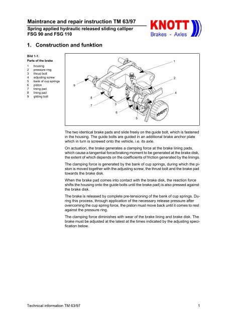
Bild 1-1:<br />
Parts of the brake<br />
1 housing<br />
2 pressure ring<br />
3 thrust bolt<br />
4 adjusting screw<br />
5 bank of cup springs<br />
6 piston<br />
7 lining pad<br />
8 lining pad<br />
9 gliding bolt<br />
1<br />
9<br />
8<br />
2<br />
4<br />
7<br />
3<br />
6<br />
5<br />
The two identical brake pads and slide freely on the guide bolt, which is fastened<br />
in the housing. The guide bolts are guided in an additional brake anchor plate<br />
which in turn is screwed onto the vehicle, i.e. its axle.<br />
On actuation, the brake generates a clamping force at the brake lining pads,<br />
which cause a tangential force/braking moment to be generated at the brake disk,<br />
the extent of which depends on the coefficients of friction generated by the linings.<br />
The clamping force is generated by the bank of cup springs, during which the piston<br />
is moved together with the adjusting screw, the thrust bolt and the brake pad<br />
towards the brake disk.<br />
When the brake pad comes into contact with the brake disk, the reaction force<br />
shifts the housing onto the guide bolts until the brake pad) is also pressed against<br />
the brake disk.<br />
The brake is released by complete pre-tensioning of the bank of cup springs. During<br />
this process, through application of the necessary release pressure after<br />
overcoming the cup spring force, the piston must move back until it comes to rest<br />
against the pressure ring.<br />
The clamping force diminishes with wear of the brake lining and brake disk. The<br />
brake must be adjusted at the latest at the times indicated by the adjusting specification<br />
below.<br />
Technical information TM 63/97 1
Maintrance and repair instruction TM 63/97<br />
Spring applied hydraulic released sliding calliper<br />
FSG 90 and FSG 110<br />
2. Mounting and basic setting regulations<br />
Basic brake setting is required after mounting new brake lining plates or brake<br />
disks, as well as during all repair stages and in the event of insufficient braking<br />
performance.<br />
Bild 2-1:<br />
Adjusting and assembly<br />
possibilties<br />
1 thrust bolt<br />
2 bank of cup springs<br />
3 adjusting screw<br />
4 screw cap<br />
5 lock nut<br />
6 piston<br />
P even surface<br />
S socket wrench<br />
1<br />
2<br />
6<br />
5<br />
3<br />
4<br />
P<br />
4<br />
S<br />
Note:<br />
2.1. Mounting the brake<br />
All mounting and basic setting work must be carried out on the brake when cold.<br />
1. Stand the vehicle on an even surface and secure against rolling away.<br />
2. Release the screw cap.<br />
3. Release the lock nut (size 24 or 30) and turn the adjusting screw anticlockwise<br />
using a size 8 or 10 socket wrench until the pressure bolt comes to rest<br />
against the even surface of the piston. In this status, the brake can be mounted<br />
onto the brake disk and fastened.<br />
4. Mount the pressure connection again.<br />
Apply the necessary release pressure to the brake until the bank of cup springs<br />
is completely pre-tensioned<br />
Following carry out the below described basic setting regulation.<br />
2 Technical information TM 63/97
Maintrance and repair instruction TM 63/97<br />
Spring applied hydraulic released sliding calliper<br />
FSG 90 and FSG 110<br />
2.2. Basic setting regulation<br />
1. Turn the adjusting screw manually clockwise until both brake pads make contact<br />
with the brake disk. Then it is not longer possible to turn the adjusting<br />
screw without exerting a major amount of force.<br />
2. Turn the adjusting screw anticlockwise in order to set the following rated clearances:<br />
type adjusting srew clearance (mm) turns<br />
FSG90 M16 (SW 8)<br />
FSG110 M20 (SW 10)<br />
min. 0,5 1/4<br />
clearance 1,0 1/2<br />
max. 1,5 3/4<br />
min. 1,0 2/5<br />
clearance 2,0 4/5<br />
max. 3,0 1 1/5<br />
2.3. Adjusting regulations<br />
3. Hold the adjusting screw in position with a hexagonal socket wrench and lock<br />
with lock nut.<br />
4. Mount the screw cap and tighten as far as possible manually.<br />
5. Stellen Sie den Druckanschluß gemäß der Vorschrift der Achs- bzw. Getriebehersteller<br />
her. Mount the pressure connection in accordance with the instructions<br />
of the axle / gear manufacturer.<br />
For bleeding the piston chamber use the socket spanner size 13 for the bleeding<br />
valve.<br />
During this adjusting process, the parking brake must be released, i.e. the bank<br />
of cup springs must be completely pre-tensioned.<br />
1. Stand the vehicle on an even surface and secure against rolling away.<br />
2. Release the parking brake by using the required release pressure.<br />
3. Release the screw cap and unscrew.<br />
4. Release the lock nut (size 24 or 30) and turn the adjusting screw with socket<br />
wrench size 8 or 10 manually clockwise until the two brake pads make contact<br />
with the brake disk.<br />
5. Turn the adjusting screw anti-clockwise and set the clearance specified in the<br />
above table.<br />
6. Hold the adjusting screw in position with the hexagonal socket wrench and<br />
lock with the lock nut.<br />
7. Mount the screw cap and tighten as far as possible manually.<br />
Actuate the brake valve several times and check the braking efficiency of the parking<br />
brake on a slope.<br />
Technical information TM 63/97 3
Maintrance and repair instruction TM 63/97<br />
Spring applied hydraulic released sliding calliper<br />
FSG 90 and FSG 110<br />
3. Emergency release of the parking brake<br />
After the failure of the pressure release the parking brake by using following manual<br />
procedure:<br />
Bild 3-1:<br />
Adjusting and assembly<br />
possibilties<br />
1 thrust bolt<br />
2 bank of cup springs<br />
3 adjusting screw<br />
4 screw cap<br />
5 lock nut<br />
6 piston<br />
P even surface<br />
S socket wrenchl<br />
1<br />
2<br />
6<br />
5<br />
3<br />
4<br />
P<br />
4<br />
S<br />
1. The vehicle has to be secured against rolling away.<br />
2. Release the screw cap and unscrew.<br />
3. Release the lock nut (size 24 or 30) and turn the adjusting screw with socket<br />
wrench size 8 or 10 manually counter-clockwise until the brake disc is free.<br />
Caution!<br />
For the emergency release is an actuation torque of 40 Nm respectively 70<br />
Nm required .<br />
4. Mount the lock nut and the screw cap and tighten both as far as possible manually.<br />
(Protection against dirt<br />
Caution!<br />
Now, the vehicle do not have any brake function. The vehicle must be secured<br />
against moving away with proper means. Before putting the vehicle<br />
into operation again, the brake has to be adjusted again. Res. „Assembly<br />
and basic setting regulations“.<br />
4 Technical information TM 63/97
Maintrance and repair instruction TM 63/97<br />
Spring applied hydraulic released sliding calliper<br />
FSG 90 and FSG 110<br />
4. Maintenance and repair work<br />
4.1. Maintenance and exchange of brake pads<br />
The brake pads themselves are maintenance free. All that is required here is a<br />
check for damaged parts, as well as inspection to ensure that the brake disk<br />
remains easy running.<br />
The thickness of the brake lining must be subjected to a visual inspection at regular<br />
intervals, which depend on vehicle usage, but every six months at the latest.<br />
In the event of a minimal residual lining thickness, these intervals must be reduced<br />
accordingly in order to avoid major damage to the brake or disk:<br />
– FSG 90:<br />
min. residual thickness 1,0 mm per lining pad (6 mm carrier plate thickness).<br />
– FSG 100:<br />
min. esidual thickness 2.0 mm per lining pad (8 mm carrier plate thickness).<br />
Bild 4-1:<br />
Extending the lining<br />
pads<br />
1 piston<br />
2 adjusting screw<br />
3 lock nut<br />
4 thrust bolt<br />
S socket wrench<br />
S1 screwdriver<br />
P inside of the piston<br />
S1<br />
1<br />
2<br />
S<br />
4<br />
P<br />
3<br />
Note:<br />
Only <strong>Knott</strong> original spare lining plates may be used. If any other spare parts are<br />
used, no warranty claims will be accepted either for the brakes or their functional<br />
characteristics<br />
1. Stand the vehicle on an even surface and secure against rolling away.<br />
2. Release the parking brake by applying the required release pressure<br />
3. Release the screw cap and unscrew.<br />
4. Release the lock nut (size 24 or 30) and turn the adjusting screw with socket<br />
wrench size 8 or 10 manually clockwise until it lies flush with the inside of the<br />
piston.<br />
5. Press back the thrust bolt using a suitable screwdriver until it has contact with<br />
the piston.<br />
Technical information TM 63/97 5
Maintrance and repair instruction TM 63/97<br />
Spring applied hydraulic released sliding calliper<br />
FSG 90 and FSG 110<br />
Bild 4-2:<br />
Exchanging the lining<br />
pads<br />
1 guide bolt<br />
2 lining pad<br />
3 lining pad<br />
4 permanent magnet<br />
5 castellated nut<br />
6a safety splint<br />
6b safety clip<br />
1<br />
6b<br />
1<br />
6a<br />
3<br />
2<br />
5<br />
4<br />
6. Depending on the free space available, release one of the two guide bolts, removing<br />
the safety splint, unscrewing the castellated nut and pulling the guide<br />
bolt out of the brake anchor plate. Now, the brake lining pads can be removed<br />
tangentially to the brake disk.<br />
Note:<br />
In the event of minimal clearance, i.e. it is not possible for space reasons to<br />
exchange the brake lining plate in accordance with these instructions, the brake<br />
must be removed completely. To do this, pull both guide bolts out of the brake<br />
anchor plate.<br />
Caution!<br />
Check the pressure hose. If the pressure hose is to short, it must be unscrewed<br />
to remove the brake. Before the pressure hose can be released the<br />
brake must be emergancy released.<br />
7. Wechseln Sie die Bremsbelagträger und führen Sie den Führungsbolzen in<br />
den Bremsträger wieder ein.<br />
Haben Sie wegen zu geringen Freiraumes die Bremse komplett entfernt,<br />
müssen Sie diese jetzt wieder einbauen und beide Führungsbolzen einführen.Exchange<br />
the brake pads and insert the guide bolts into the brake anchor<br />
plate.If you have removed the complete brake you have to amount the brake<br />
on both guide bolt again, now.<br />
8. Check both permanent magnets if they still have sufficient magnetic force to<br />
hold the brake lining plates.<br />
Should this not be the case, the permanent magnets must also be changed<br />
by using a suitable screw driver.<br />
9. Secure the guide bolt with the castellated nut and the safety splint res. safety<br />
clip.<br />
Note:<br />
After mounting new brake lining plates or their repair, the brake must be correctly<br />
set in accordance with the instructions „Adjusting regulations“.<br />
6 Technical information TM 63/97
Maintrance and repair instruction TM 63/97<br />
Spring applied hydraulic released sliding calliper<br />
FSG 90 and FSG 110<br />
4.2. Changing the seal<br />
Bild 4-3:<br />
Change of the sealsl<br />
1 piston<br />
2 adjusting screw<br />
3 lock nut<br />
4 housing<br />
5 circlip<br />
6 seal<br />
7 guide bolt<br />
8 thrust bolt<br />
9 bank of cup spring<br />
A detail of the seal<br />
B detail of the seal<br />
A<br />
B<br />
3<br />
2<br />
1<br />
8<br />
9<br />
7<br />
6<br />
5<br />
4<br />
Faulty seals must be exchanged in accordance with the instructions below:<br />
1. Stand the vehicle on an even surface and secure against rolling away.<br />
2. Release the parking brake by applying the necessary release pressure.<br />
3. Release the screw cap and unscrew.<br />
4. Release the lock nut (size 24 or 30) and turn the adjusting screw with socket<br />
wrench size 8 or 10 manually counter clockwise until the adjuster screw is<br />
flush with the inner side of the piston.<br />
5. Push back the thrust bolt until it has contact with the piston. Following actuate<br />
the hand brake valve. (no pressure must be in the piston chamber). The bank<br />
of cup springs is now completely depressurized.<br />
6. Unscrew the pressure hose and remove the brake.<br />
7. Release the circlip and remove the pressure ring of the housing.<br />
8. Release the bank of cup spings and the piston.<br />
Caution!<br />
Pay attention to the mounting direction of the seal rings, otherwise leaks<br />
can occur.<br />
Use for mounting the new seal rings a suitable mounting needle with rounded<br />
edge. Be careful,<br />
Technical information TM 63/97 7
Maintrance and repair instruction TM 63/97<br />
Spring applied hydraulic released sliding calliper<br />
FSG 90 and FSG 110<br />
4.3. General<br />
9. Change all seals and mount the parts of the brake in other way round order.<br />
By mounting the piston, the sliding and sealing surfaces must be greased lightly<br />
using lubricating grease to DIN 51825.<br />
The dust protection cap is fitted with a vulcanized-in steel ring which is used<br />
to press it through the locating hole. For exchanging, "lever out" the ring using<br />
a suitable tool. The new dust protection cap must be pressed in with the aid<br />
of a suitable mounting ring and screw clamps or a lever press.<br />
Mount the brake in accordance with the above procedure into the vehicle / at the<br />
axle.<br />
Any discovered defects or damage to parts not listed here must naturally be repaired<br />
or replaced using original parts.<br />
For any other information not contained in these instructions or for more detailed<br />
instructions, please contact the vehicle or brake manufacturer<br />
8 Technical information TM 63/97