Maintenance and Repair Instructions TM 89/03 - Knott Brake Company
Maintenance and Repair Instructions TM 89/03 - Knott Brake Company
Maintenance and Repair Instructions TM 89/03 - Knott Brake Company

Create successful ePaper yourself
Turn your PDF publications into a flip-book with our unique Google optimized e-Paper software.
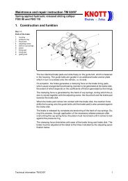
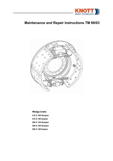
<strong>Maintenance</strong> <strong>and</strong> <strong>Repair</strong> <strong>Instructions</strong> <strong>TM</strong> <strong>89</strong>/<strong>03</strong>Wedge brake410 X 180 Simplex410 X 180 Duplex500 X 120 Simplex500 X 160 Simplex500 X 180 Duplex
<strong>Maintenance</strong> <strong>and</strong> <strong>Repair</strong> <strong>Instructions</strong>Wedge brakeThe brake described in this manual is subject to development <strong>and</strong> corresponds tothe state-of-the-art at the time of publication.The manufacturer reserves the right to make changes in engineering, design <strong>and</strong>specifications or add improvements at any time. Some details of the brakes suppliedmay therefore vary from the version described.© <strong>Knott</strong> GmbH 2006. All rights reserved.2 Technical information <strong>TM</strong> <strong>89</strong>/<strong>03</strong>
<strong>Maintenance</strong> <strong>and</strong> <strong>Repair</strong> <strong>Instructions</strong>Wedge brakeContents1 Safety instructions 52 Construction <strong>and</strong> function 62.1 General Layout - Simplex <strong>Brake</strong> 62.2 General Layout - Duplex <strong>Brake</strong> 72.3 Operation of the exp<strong>and</strong>er mechanism 82.4 Automatic self-adjustment mechanism 93 Inspecting the brakes 1<strong>03</strong>.1 Checking the thickness of the brake linings 1<strong>03</strong>.2 Checking the brake shoes <strong>and</strong> brake linings 1<strong>03</strong>.3 Visual inspection of the brake drums 113.4 Visual inspection <strong>and</strong> functional test of the exp<strong>and</strong>er mechanism 113.5 Other brake parts 114 Replacement of wear parts 124.1 General safety instructions for maintenance <strong>and</strong> repair work 124.2 Removing <strong>and</strong> refitting the brake drum 13Slackening/tightening the automatic self-adjustment mechanism 13Removal of brake drum 14Fitting of brake drum 144.3 Replacing the brake shoes 15Tools <strong>and</strong> torques 15Removing the brake shoes 16Fitting the brake shoes (Simplex brake) 17Fitting the brake shoes (Duplex brake) 184.4 Removing <strong>and</strong> refitting the exp<strong>and</strong>er mechanism 194.5 Removing <strong>and</strong> refitting the exp<strong>and</strong>er mechanism 20Tools <strong>and</strong> torques 20Removing <strong>and</strong> refitting the exp<strong>and</strong>er mechanism 205 Function test <strong>and</strong> burnishing process 21Functional test of the wedge brake 21Burnishing of brake linings 216 Appendix 226.1 Necessary documents, tools <strong>and</strong> equipment 22Notes: 22Tools: 22Lubricants <strong>and</strong> operating materials 22Technical information <strong>TM</strong> <strong>89</strong>/<strong>03</strong> 3
<strong>Maintenance</strong> <strong>and</strong> <strong>Repair</strong> <strong>Instructions</strong>Wedge brake4 Technical information <strong>TM</strong> <strong>89</strong>/<strong>03</strong>
<strong>Maintenance</strong> <strong>and</strong> <strong>Repair</strong> <strong>Instructions</strong>Wedge brake1. Safety instructionsRead these instructions thoroughly before starting work. All information<strong>and</strong> instructions therein must be strictly observed!<strong>Maintenance</strong> <strong>and</strong> servicing of brakes must be carried out by speciallytrained personnel!All applicable accident prevention regulations must be complied with!Negligence in the execution or failure to carry out maintenance work willrender all warranty conditions invalid. In such an event, KNOTT GmbH cannotbe held responsible for any damage incurred!Beware: Danger of injury!Before commencing maintenance <strong>and</strong> repair work on the brakes, the vehiclemust be secured to prevent it rolling off!Beware: Danger of injury!Before commencing work on the brake, ensure that the brake cannot beoperated unintentionally!Caution!Before starting any assembly work on the actuating cylinders, make surethat there is no actuating pressure <strong>and</strong> that no actuating pressure canbuild up while the work is being carried out.Spring actuating cylinders must be released manually before carrying outmaintenance <strong>and</strong> assembly work!Technical information <strong>TM</strong> <strong>89</strong>/<strong>03</strong> 5
<strong>Maintenance</strong> <strong>and</strong> <strong>Repair</strong> <strong>Instructions</strong>Wedge brake2. Construction <strong>and</strong> function2.1. General Layout - Simplex <strong>Brake</strong>Figure 2-1:General layout ofsimplex brake1 Exp<strong>and</strong>ermechanism2 <strong>Brake</strong> shoe3 Tension spring4 <strong>Brake</strong> back plate5 <strong>Brake</strong> shoe anchor6 Dust shield62123435The main components of a simplex brake are the brake back plate, the brake anchor,a exp<strong>and</strong>er mechanism, the brake shoes, the dust shield <strong>and</strong> the tensionspringsThe brake shoes are supported by the brake shoe anchor. When the brakes areactuated the exp<strong>and</strong>er mechanism pushes the brake shoes against the inside ofthe brake drum. When the brakes are released the tension springs pull the brakeshoes back to their original position.The dust shield prevents the ingress of water <strong>and</strong> dust into the brake.The brake shoe that is pushed away from the exp<strong>and</strong>er mechanism during forwardmotion is the leading shoe. Due to the simplex mechanism the leading shoeis subject to higher wear than the trailing brake shoe.The braking power is approximately equal in both forward <strong>and</strong> reverse.Technical information <strong>TM</strong> <strong>89</strong>/<strong>03</strong> 6
<strong>Maintenance</strong> <strong>and</strong> <strong>Repair</strong> <strong>Instructions</strong>Wedge brake2.2. General Layout - Duplex <strong>Brake</strong>Figure 2-2:General layout ofduplex brake1 Spreadingmechanism2 <strong>Brake</strong> shoe3 Tension spring4 Compressionspring5 <strong>Brake</strong> back plate6 Dust shield621234531The main components of a duplex brake are the brake back plate, two exp<strong>and</strong>ermechanisms, the brake shoes, the dust shield <strong>and</strong> the tension springsThe brake shoes are held on the back plate by compression springs. When thebrakes are actuated the exp<strong>and</strong>er mechanisms push the brake shoes against theinside of the brake drum. When the brakes are released the tension springs pullthe brake shoes back to their original position.The dust shield prevents the ingress of water <strong>and</strong> dust into the brake.Due to the dual actuation of the brake shoes <strong>and</strong> the wedge shaped face betweenthe brake shoes <strong>and</strong> the stud bolts, both shoes act as leading shoes in reverse<strong>and</strong> forward motion.As a result the duplex brake has a stronger braking action than the simplex brake.The braking power is approximately equal in both forward <strong>and</strong> reverse.Technical information <strong>TM</strong> <strong>89</strong>/<strong>03</strong> 7
<strong>Maintenance</strong> <strong>and</strong> <strong>Repair</strong> <strong>Instructions</strong>Wedge brake2.3. Operation of the exp<strong>and</strong>er mechanismFigure 2-3:exp<strong>and</strong>er mechanism1 Housing2 Wedge3 Stud bolt4 Cup seal5 Pressure roller6 Compressionspring7 Self-adjustmentmechanism7312 3456The main components of the exp<strong>and</strong>er mechanism are the housing, a wedge,pressure rollers <strong>and</strong> stud bolts. Cup seals prevent the ingress of dirt <strong>and</strong> waterinto the exp<strong>and</strong>er mechanism.Upon brake actuation the wedge is pushed by the actuating cylinder into the exp<strong>and</strong>ermechanism. This results in actuation of the stud bolts via the rollers.<strong>Brake</strong> shoe wear is compensated by an automatic self-adjustment mechanism.As a result, pedal travel remains roughly the same during the entire service life ofthe brake shoes.When the brake is released the compression spring returns the wedge to its originalposition.Duplex brakes have one self-adjustment mechanism per exp<strong>and</strong>er mechanism,whereas in simplex brakes both stud bolts feature a self-adjustment mechanism.Note:For duplex brakes the exp<strong>and</strong>er mechanism must be fitted in such a way that thebrake shoe is pushed away from the automatic self-adjustment mechanism bythe brake drum during forward motion.8 Technical information <strong>TM</strong> <strong>89</strong>/<strong>03</strong>
<strong>Maintenance</strong> <strong>and</strong> <strong>Repair</strong> <strong>Instructions</strong>Wedge brake2.4. Automatic self-adjustment mechanismFigure 2-4:Automatic self-adjustmentmechanism1 Stud bolt2 Adjusting plunger3 Adjuster sleeve4 Adjuster bolt withpawl5 Retainer12 3 4 5The automatic self-adjustment mechanism is a mechanical actuator between studbolt <strong>and</strong> brake shoe. The main components of the self-adjustment mechanism arethe adjuster sleeve, the adjuster bolt with pawl, the spring-loaded adjusting plunger<strong>and</strong> the retainer with leaf spring.The adjuster sleeve together with the threaded adjuster bolt is located in a blindhole inside the stud bolt. The helical teeth of the adjusting plunger engage withthe helical teeth of the adjuster sleeve through an elongated hole in the stud bolt.When the actuating distance of the stud bolt during braking is longer than the distancebetween the helical teeth (due to brake lining wear), the spring-loaded adjustingplunger engages with the next tooth of the helical gear of the adjustersleeve.When the brake is released, the adjuster sleeve is rotated by one tooth pitch. Thespring-loaded retainer prevents the rotation of the adjuster bolt, so that the bolt isunscrewed one turn from the adjuster sleeve in order to compensate for liningwear.To facilitate removal of the brake drum, the pawl can be used to screw the adjusterbolt back into the adjuster sleeve.Technical information <strong>TM</strong> <strong>89</strong>/<strong>03</strong> 9
<strong>Maintenance</strong> <strong>and</strong> <strong>Repair</strong> <strong>Instructions</strong>Wedge brake3. Inspecting the brakesCaution!Before commencing maintenance <strong>and</strong> repair work on the brakes, the vehiclemust be secured to prevent it rolling off!Before commencing work on the brake, ensure that the brake cannot be operatedunintentionally!3.1. Checking the thickness of the brake liningsThe thickness of the brake linings should be checked visually at intervals accordingto the amount of use to which the vehicle is put (<strong>and</strong> no later than every 3months).1. Remove the blanking plugs of the dust shield.2. Check whether the wear edge of the brake linings is still visible.When the wear edge of the brake linings is no longer visible, the brake liningsneed to be replaced.When the lining thickness is approaching the residual lining thickness, the inspectionintervals should be shortened accordingly.3.2. Checking the brake shoes <strong>and</strong> brake liningsThe brake shoes should be checked visually at intervals according to the amountof use to which the vehicle is put (<strong>and</strong> no later than every 6 months). Remove thebrake drums in order to perform this check.Caution!<strong>Brake</strong> linings must only be riveted to the brake shoes by an authorisedspecialist company! Always use genuine replacement parts!Note:The steps for removal <strong>and</strong> re-fitting of the brake drum are dependent on axleconfiguration. Consult the corresponding documentation of the axle manufacturer!The brake linings must be replaced if:• the wear edge of the brake linings is no longer visible,• the braking surface is glazed,• the brake lining has been damaged by heat, or• the brake linings show surface cracks.Note:The brake shoes should be re-conditioned by <strong>Knott</strong>; state the internal diameterof the braking surface of the drums when placing your order!Technical information <strong>TM</strong> <strong>89</strong>/<strong>03</strong> 10
<strong>Maintenance</strong> <strong>and</strong> <strong>Repair</strong> <strong>Instructions</strong>Wedge brakeReplace the brake shoes if:• the sliding surfaces on the shoe web are worn or damaged,• the brake shoes have been damaged by corrosion, or• the brake shoes are deformed.3.3. Visual inspection of the brake drumsCheck the brake drums for grooving, cracks <strong>and</strong> wear whenever the brake shoesare changed.Note:The wear limits of the brake drums are specified by the axle manufacturer. Consultthe documentation provided by the axle manufacturer.3.4. Visual inspection <strong>and</strong> functional test of the exp<strong>and</strong>er mechanism3.5. Other brake partsWhenever the brake shoes are being replaced, inspect the exp<strong>and</strong>er mechanismas follows:• Visual check for damage of bellows.Replace the corresponding parts if damage is evident.• Check that the self-adusting mechanism turns freely.If this is not the case, replace the stud bolt of the self-adjustment mechanism.• Check that the adjuster bolts turn freely.If this is not the case, replace the exp<strong>and</strong>er mechanism.The compression <strong>and</strong> tension springs <strong>and</strong> the sealing rings, protective caps <strong>and</strong>bellows should be replaced at least every 2 years, or earlier if they are worn.Note:Always use new tension <strong>and</strong> compression springs when the brake shoes havebeen removed for maintenance <strong>and</strong> repair purposes!Technical information <strong>TM</strong> <strong>89</strong>/<strong>03</strong> 11
<strong>Maintenance</strong> <strong>and</strong> <strong>Repair</strong> <strong>Instructions</strong>Wedge brake4. Replacement of wear parts4.1. General safety instructions for maintenance <strong>and</strong> repair workThe following instructions must be followed when carrying out maintenance <strong>and</strong>repair work on the brake system.Beware: Danger of injury!Before commencing maintenance <strong>and</strong> repair work on the brakes, the vehiclemust be secured to prevent it rolling off!Beware: Danger of injury!When working beneath a raised vehicle, the vehicle must be secured onsuitable supports to prevent it falling off.Make absolutely sure that the supports have sufficient load-bearing capacity<strong>and</strong> are positioned at suitable points on the vehicle!Beware: Danger of injury!Before commencing work on the brake, ensure that the brake cannot beoperated unintentionally!Caution!Parts subject to wear must be replaced axle by axle!Caution!<strong>Brake</strong> linings must only be riveted to the brake shoes by an authorisedspecialist company! Always use genuine replacement parts!Caution!If the brakes are actuated via a spring actuation cylinder, use the emergencyrelease device to prevent accidental actuation of the brakes!Technical information <strong>TM</strong> <strong>89</strong>/<strong>03</strong> 12
<strong>Maintenance</strong> <strong>and</strong> <strong>Repair</strong> <strong>Instructions</strong>Wedge brake4.2. Removing <strong>and</strong> refitting the brake drumSlackening/tightening the automatic self-adjustment mechanismCaution!After fitting the brake drum the brake must be adjusted using the selfadjustingmechanism! If the automatic adjusting mechanism is left in itsbottom position, the brake will not automatically adjust itself.Note:Each wedge brake has two automatic self-adjusting mechanisms:– Simplex brake: at Pos. 1 <strong>and</strong> 2– Duplex brake, left h<strong>and</strong> side of vehicle: at Pos. 2 <strong>and</strong> 3– Duplex brake, right h<strong>and</strong> side of vehicle: at Pos. 1 <strong>and</strong> 4Figure 4-1:Rear of wedge brake(drawing)1 exp<strong>and</strong>er mechanism2 Dust shield1 2123 41. Remove the blanking plugs of the dust shield.2. Use a screwdriver inserted into the dust shield hole to rotate the self-adjustmentmechanism in reverse direction.Item123AdjustmentdirectionupwardsdownwardsupwardsdownwardsupwardsdownwardsEffect on brakeTighten brakeRelease brakeRelease brakeTighten brakeTighten brakeRelease brakeupwards Release brake4downwards Tighten brakeTab. 4.1 Effect of adjusting the pawl (via the adjustment hole at the rear ofthe brake)Technical information <strong>TM</strong> <strong>89</strong>/<strong>03</strong> 13
<strong>Maintenance</strong> <strong>and</strong> <strong>Repair</strong> <strong>Instructions</strong>Wedge brakeRemoval of brake drum1. Undo the automatic self-adjustment mechanisms. See “Slackening/tighteningthe automatic self-adjustment mechanism” on page 13.Note:The steps for fitting <strong>and</strong> removal of the brake drum are dependent on axle construction.Consult the corresponding documentation of the axle manufacturer!2. Remove the brake drum from the brake assembly.Fitting of brake drumCaution!Follow the instructions for burnishing if you are using new brake linings<strong>and</strong>/or brake drums. See “Burnishing of brake linings” on page 21.Note:The allowable limits for damage <strong>and</strong> wear of the brake drum are dependent onaxle construction! Consult the corresponding documentation of the axle manufacturer!If scoring can be seen on the braking surfaces of the brake drum, thesewill have to be machined in accordance with the specifications of the axle manufacturer.The steps for fitting <strong>and</strong> removal of the brake drum are dependent on axle construction.Consult the corresponding documentation of the axle manufacturer.1. Using a suitable tool thread the adjuster bolts of both self-adjustment mechanismto the bottom of the adjuster sleeve <strong>and</strong> then back it out by approx. 1turn.2. Remove all dirt <strong>and</strong> rust from the brake drum <strong>and</strong> the brake linings.3. Check brake tension <strong>and</strong> compression springs for obvious damage. Damagedcomponents must be replaced.4. Check the brake drum for cracks <strong>and</strong> scoring.5. Remove any protrusions of the inside of the braking surface with a suitabletool when refitting the brake drum.6. Fit the brake drum. Consult the fitting instructions of the axle manufacturer!7. Using a suitable tool turn the adjustment bolt of the self-adjustment mechanismuntil the drum can no longer be rotated by h<strong>and</strong>. See “Slackening/tighteningthe automatic self-adjustment mechanism” on page 13..8. Slacken the self-adjustment mechanism 3 - 4 teeth until the brake drum canbe rotated again.9. Repeat this procedure for the second self-adjustment mechanism.14 Technical information <strong>TM</strong> <strong>89</strong>/<strong>03</strong>
<strong>Maintenance</strong> <strong>and</strong> <strong>Repair</strong> <strong>Instructions</strong>Wedge brake4.3. Replacing the brake shoesCaution!Follow the instructions for burnishing if you are using new brake linings<strong>and</strong>/or brake drums. See “Burnishing of brake linings” on page 21.Note:When using new brake linings, these must be matched to the internal dimensionof the brake drum! Always specify the internal dimension of the braking surfaceof the drum when ordering brake shoes!Note:If the original brake drums are being reused, the brake lining edges can bechamfered to 45° with a file in order to facilitate re-assembly!Note:Remove any dirt from the brake linings, such as greasy fingerprints, using emerycloth or an abrasive pad.Tools <strong>and</strong> torquesNecessary tools <strong>and</strong> torques:Item. no.. Designation DescriptionSpring pliersSpring compressorM(Nm)Technical information <strong>TM</strong> <strong>89</strong>/<strong>03</strong> 15
l<strong>Maintenance</strong> <strong>and</strong> <strong>Repair</strong> <strong>Instructions</strong>Wedge brakeRemoving the brake shoesBeware: Danger of injury!Risk of injury from the pre-stressed tension springs. When removing thebrake shoes, there is a risk of injury due to the tension springs snappingback. Use spring pliers to detach the tension springs.Figure 4-2:12Removing the brakeshoes1 Duplex brake2 Simplex brake3 Tension spring4 Compressionspring5 <strong>Brake</strong> shoes6 <strong>Brake</strong> shoe anchor5343335561. Remove the brake drum.See “Slackening/tightening the automatic self-adjustmentmechanism” on page 13.2. Using spring pliers, release [unhook] the tension springs.For simple brakes3. Remove the brake shoes <strong>and</strong> check the grooved pins in the brake shoeanchor for damage.For duplex brakes3. Unhook the compression springs using a spring compressor.4. Remove the brake shoes.5. Check all components for damage <strong>and</strong> wear.16 Technical information <strong>TM</strong> <strong>89</strong>/<strong>03</strong>
<strong>Maintenance</strong> <strong>and</strong> <strong>Repair</strong> <strong>Instructions</strong>Wedge brakeFitting the brake shoes (Simplex brake)Beware: Danger of injury!Risk of injury when attaching the tension springs. When fitting the brakeshoes, there is a risk of injury due to the tension springs snapping back.Use spring pliers to attach the tension springs.Figure 4-3:Fitting the brakeshoes - Simplex brake1 Self-adjustmentmechanism2 <strong>Brake</strong> shoe3 Adjuster bolt4 Tension spring5 <strong>Brake</strong> shoe anchor6 Grooved pin21 2342651. Using a suitable tool thread the adjuster bolts of both self-adjustment mechanismto the bottom of the adjuster sleeve <strong>and</strong> then back it out by approx. 1turn.2. Lightly grease the adjuster bolt <strong>and</strong> the face of the brake anchor using coppergrease.3. Check the grooved pin of the brake anchor for damage <strong>and</strong> make sure that itis fully inserted into the brake anchor.4. Attach the brake shoes to the brake anchor.5. Refit the tension springs to the brake shoes.6. Fit the brake drums. See “Fitting of brake drum” on page 14.Technical information <strong>TM</strong> <strong>89</strong>/<strong>03</strong> 17
<strong>Maintenance</strong> <strong>and</strong> <strong>Repair</strong> <strong>Instructions</strong>Wedge brakeFitting the brake shoes (Duplex brake)Beware: Danger of injury!Risk of injury when attaching the tension springs. When fitting the brakeshoes, there is a risk of injury due to the tension springs snapping back.Use spring pliers to attach the tension springs.Figure 4-4:Replacing the brakelinings1 Adjuster bolt2 Stud bolt bearingsurface3 <strong>Brake</strong> shoes4 Compressionspring5 Tension spring6 <strong>Brake</strong> anchor plate5651242361. Using a suitable tool thread the adjuster bolts of both self-adjustment mechanismto the bottom of the adjuster sleeve <strong>and</strong> then back it out by approx. 1turn.2. Ensure that the raised side of the ramp shaped face of the stud bolts is pointingtowards the outside.3. Grease the stud bolts <strong>and</strong> those areas where the brake shoes come into contactwith the anchor plate using copper grease.Caution!The arrow on the brake shoe web plate must point in the direction of forwardtravel (rotational direction of the brake drum)!4. Insert the brake shoes in the stud bolts.5. Hook the compressions springs through the brake shoe holes into the brakeshoe web.Note:Make sure that the bent ends of the compression springs are hooked into theindentations on the rear of the brake back plate.6. Refit the tension springs to the brake shoes.7. Fit the brake drums. See “Fitting of brake drum” on page 14.18 Technical information <strong>TM</strong> <strong>89</strong>/<strong>03</strong>
<strong>Maintenance</strong> <strong>and</strong> <strong>Repair</strong> <strong>Instructions</strong>Wedge brake4.4. Removing <strong>and</strong> refitting the exp<strong>and</strong>er mechanismRemoving <strong>and</strong> refitting the exp<strong>and</strong>er mechanismBeware: Danger of injury!Before commencing work on the brake, ensure that the brake cannot beoperated unintentionally!Caution!If the brakes are actuated via a spring actuation cylinder, use the emergencyrelease device to prevent accidental actuation of the brakes!Figure 4-5:Removing <strong>and</strong> refittingthe exp<strong>and</strong>ermechanism1 Wedge2 Compressionspring3 Boot4 Pressure roller5 Stud bolt1 2 35 451. Remove the actuating cylinder from the exp<strong>and</strong>er mechanism (see <strong>TM</strong> 98/05).2. Pull the wedge from the exp<strong>and</strong>er mechanism.Note:Ensure that you remove the boot, the compression spring <strong>and</strong> both actuatingrollers together with the wedge!Caution!It must be possible to insert the wedge into the exp<strong>and</strong>er mechanism untilthe boot is flush against the housing of the exp<strong>and</strong>er mechanism withoutusing force!3. Refitting is the reverse sequence to removal; ensure that the thrust rollers arepointing in the direction of the stud bolts.Note:Grease the wedge <strong>and</strong> the thrust rollers using st<strong>and</strong>ard high pressure universalgrease.Technical information <strong>TM</strong> <strong>89</strong>/<strong>03</strong> 19
<strong>Maintenance</strong> <strong>and</strong> <strong>Repair</strong> <strong>Instructions</strong>Wedge brake4.5. Removing <strong>and</strong> refitting the exp<strong>and</strong>er mechanismTools <strong>and</strong> torquesRequired tools <strong>and</strong> torques:Item. no.. Designation DescriptionM(Nm)3 Ring spanner WAF 19 195 - 225Removing <strong>and</strong> refitting the exp<strong>and</strong>er mechanismBeware: Danger of injury!Before commencing work on the brake, ensure that the brake cannot beoperated unintentionally!Caution!If the brakes are actuated via a spring actuation cylinder, use the emergencyrelease device to prevent accidental actuation of the brakes!Figure 4-6:Removing <strong>and</strong> refittingthe exp<strong>and</strong>ermechanism211 21 exp<strong>and</strong>er mechanism2 <strong>Brake</strong> back plate3 Assembly bolt331. Remove the brake drum.See “Slackening/tightening the automatic self-adjustmentmechanism” on page 13.2. Remove the brake shoes. See “Removing the brake shoes” on page 16.3. Remove the actuating cylinder from the exp<strong>and</strong>er mechanism (see <strong>TM</strong> 98/05).4. Unscrew the assembly bolts of the exp<strong>and</strong>er mechanism.5. Remove the exp<strong>and</strong>er mechanism from the brake back plate.6. Reverse the above sequence to fit.20 Technical information <strong>TM</strong> <strong>89</strong>/<strong>03</strong>
<strong>Maintenance</strong> <strong>and</strong> <strong>Repair</strong> <strong>Instructions</strong>Wedge brake5. Function test <strong>and</strong> burnishing processFunctional test of the wedge brakeThe wedge brake function should only be tested on a rolling road dynamometer.Burnishing of brake liningsBeware: Danger of injury!Risk of accident when applying the brakes on public roads. The brakesshould be burnished by applying the brakes continuously on a rolling roaddynamometer.If the brakes are burnished on public roads, particular attention should bepaid to traffic behind the vehicle in order to avoid rear-end collisions.To allow new brake linings to achieve maximum braking power, the brake mustbe burnished after the brake linings are changed.Burnishing by continuous braking• Bed in the brake on the dynamometer or while driving by applying light brakingpressure.• Release the brake several times while bedding in to allow the binder in thelinings to outgas.• The temperature of the brake drum should not exceed 250° C in this way.• Once the brakes have cooled down, test the braking power that can beachieved, <strong>and</strong> repeat the burnishing process until the prescribed brakingpower is achieved.Burnishing by stop brakingCaution!Avoid braking sharply with strong deceleration during the burnishingprocess.• Carry out stop brakings with medium pressure <strong>and</strong> medium speed unless abrake drum temperature of approx. 250° C is achieved.• Once the brakes have cooled down, test the braking power that can beachieved, <strong>and</strong> repeat the burnishing process until the prescribed brakingpower is achieved.Technical information <strong>TM</strong> <strong>89</strong>/<strong>03</strong> 21
<strong>Maintenance</strong> <strong>and</strong> <strong>Repair</strong> <strong>Instructions</strong>Wedge brake6. Appendix6.1. Necessary documents, tools <strong>and</strong> equipmentNotes:• <strong>Maintenance</strong> <strong>and</strong> <strong>Repair</strong> <strong>Instructions</strong> <strong>TM</strong> <strong>89</strong>/<strong>03</strong>• Fitting instructions <strong>TM</strong> 98/05Tools:• The usual workshop tools are required for fitting <strong>and</strong> dismantling work.• Special toolsWe also recommend the use of the following tools <strong>and</strong> equipment, whichcan be ordered by article number from the KNOTT spare parts service.DesignationArt. no. or specificationSpring pliersSpring compressorLubricants <strong>and</strong> operating materialsLubricant or service materialType or designationMineral oil based grease, Lithium grease, EP,NLG2e.g. Fuchs Renolit Duraplex EP2Copper greaseAbrasive pad, emery cloth Grit 120Technical information <strong>TM</strong> <strong>89</strong>/<strong>03</strong> 22