B r a k e s - A xl e s - Knott Brake Company
B r a k e s - A xl e s - Knott Brake Company
B r a k e s - A xl e s - Knott Brake Company

You also want an ePaper? Increase the reach of your titles
YUMPU automatically turns print PDFs into web optimized ePapers that Google loves.
KNOTT<br />
B r a k e s - A x l e s<br />
KNOTT <strong>Brake</strong> <strong>Company</strong> Tel: (330) 722-5200<br />
4930 Chippewa Road 1-800-KNOTT-US<br />
Medina, OH 44256 Fax: (330) 723-2399<br />
U.S.A. www.knottbrake.com<br />
TECHNICAL INFORMATION<br />
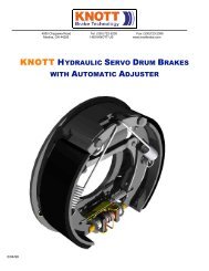
Automatic Adjuster for Hydraulic Servo <strong>Brake</strong>s<br />
Functional Characteristics and Mounting Instructions<br />
1. Functional characteristics of hydraulic servo brakes<br />
The functional principle of this brake is the application of the two brake shoes in the brake drum after expansion<br />
of the wheel cylinder. One brake shoe (primary shoe) is driven in the sense of rotation of the<br />
brake drum. The secondary shoe, determined by its floating suspension, rests against an upper fixed<br />
stop at the brake plate. The resulting travel of the brake shoes is used to actuate the automatic adjuster.<br />
2. Automatic adjuster<br />
2.1 Function and working method<br />
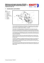
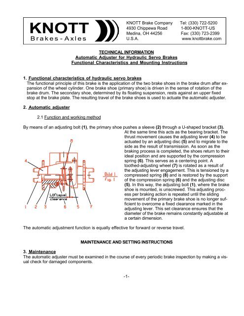
By means of an adjusting bolt (1), the primary shoe pushes a sleeve (2) through a U-shaped bracket (3).<br />
At the same time this acts as the bearing bracket. The<br />
thrust movement causes the adjusting lever (4) to be<br />
actuated by an adjusting disc (5) and to migrate to the<br />
side as the result of transmission. As soon as the<br />
braking process is completed, the shoes return to their<br />
ideal position and are supported by the compression<br />
spring (6). This serves as a centering point. A<br />
toothed-adjusting wheel (7) is rotated as a result of<br />
the adjusting lever engagement. This is tensioned by a<br />
compressed spring (8) and is restored by the support<br />
of the compression spring (6) and the adjusting disc<br />
(5). In this way, the adjusting bolt (1), where the brake<br />
shoe is mounted, is unscrewed. This adjusting process<br />
per braking action is repeated until the sliding<br />
movement of the primary brake shoe is no longer sufficient<br />
to overcome a fixed clearance marked in the<br />
adjusting lever. This set clearance ensures that the<br />
diameter of the brake remains constantly adjustable at<br />
a certain dimension.<br />
The automatic adjustment function is equally effective for forward or reverse travel.<br />
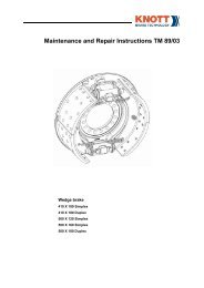
MAINTENANCE AND SETTING INSTRUCTIONS<br />
3. Maintenance<br />
The automatic adjuster must be examined in the course of every periodic brake inspection by making a visual<br />
check for damaged components.<br />
-1-
KNOTT<br />
B r a k e s - A x l e s<br />
KNOTT <strong>Brake</strong> <strong>Company</strong> Tel: (330) 722-5200<br />
4930 Chippewa Road 1-800-KNOTT-US<br />
Medina, OH 44256 Fax: (330) 723-2399<br />
U.S.A. www.knottbrake.com<br />
Note:<br />
No repairs may be carried out on the automatic adjuster. If necessary, the entire adjuster unit must be exchanged.<br />
The adjuster is largely maintenance-free. All that is necessary is to lightly grease the thread of the adjusting<br />
bolt (1) when dismantling the brake shoes with a heat-resistant grease (at intervals of max. 500 hours).<br />
When soiled, the adjuster may only be cleaned using compressed air. Do not dismantle individual components.<br />
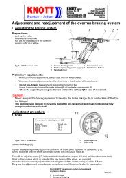
4. Setting specification:<br />
<strong>Brake</strong> setting is essential when:<br />
4.1 Renewing, removing or mounting the automatic adjuster.<br />
4.2 Mounting new brake shoes and brake drums at all stages of repair.<br />
4.3 Repair work on the brake, when the basic setting of the threaded bolts (Fig. 2) has been<br />
altered at the automatic adjuster.<br />
Setting work, as well as checking the clearance between the brake shoes and brake drum must be carried<br />
out when the brake is cold. The driving and parking brake must always be adjusted together.<br />
5. Setting procedure:<br />
During setting, the parking brake must be released (the cables should not be tensioned).<br />
5.1 Jack up the vehicle.<br />
5.2 Release the brake cables<br />
-2-
KNOTT<br />
B r a k e s - A x l e s<br />
5.3 Remove the brake drum<br />
KNOTT <strong>Brake</strong> <strong>Company</strong> Tel: (330) 722-5200<br />
4930 Chippewa Road 1-800-KNOTT-US<br />
Medina, OH 44256 Fax: (330) 723-2399<br />
U.S.A. www.knottbrake.com<br />
Caution:<br />
With run-in brake drums, remember that when resetting the adjusting wheel, it is locked by the<br />
adjusting lever. Do not use force. Carefully raise the adjusting lever using a screwdriver or similar tool<br />
through the opening in the brake plate to permit the adjusting wheel to turn freely.<br />
5.4 Adjust setting dimension "A" (see Fig. 2) in accordance with the following breakdown by<br />
adjusting screw (1) of the automatic adjuster.<br />
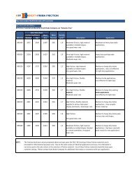
Adjuster Part Setting Dimension<br />
<strong>Brake</strong> Size (mm)<br />
Number<br />
“A”<br />
36113.01 54 160x35, 170x40, 200x50<br />
36130.01/.02<br />
60 200x40<br />
36156.01/.02<br />
60 203x60<br />
35856.01/.02 79 203x60, 200x40<br />
35878.01/.02 85 245x60, 300x55<br />
35914.01/.02<br />
79 228,5x50, 245x60, 250x55<br />
35914.03/.04<br />
230x50, 260,4x57, 267x64<br />
35916.01/.02/.0<br />
2<br />
84/80 250x60, 270x60, 310x60<br />
35959.01 85<br />
36160.01/.02/.0 100 315/325x80, 400x80<br />
3<br />
100 432x90, 438,2x10²<br />
36160.01/.02/.0<br />
3<br />
36165.01<br />
100 270x60<br />
Note:<br />
During this setting work, take care to ensure an even distance "B" of the adjusting screws (1) to the relevant<br />
adjusting wheel (7).<br />
5.5 If necessary, adjust this evenly at the two adjusting gears (7), as specified in the instructions after<br />
checking the brake diameter.<br />
Note:<br />
Precise adjustment of the relevant brake diameter is of decisive importance for the function of the automatic<br />
adjuster. An insufficiently high setting could result in damage to the adjuster.<br />
5.6 Adjust the brake cables in such a way that the relevant brake diameter is not altered.<br />
Note:<br />
The brake cables may not be pretensioned. Otherwise it is not possible to guarantee perfect function of the<br />
adjuster.<br />
5.7 Mount the brake drum.<br />
-3-
KNOTT<br />
B r a k e s - A x l e s<br />
5.8 Release hexagon bolt for fastening the automatic adjuster.<br />
KNOTT <strong>Brake</strong> <strong>Company</strong> Tel: (330) 722-5200<br />
4930 Chippewa Road 1-800-KNOTT-US<br />
Medina, OH 44256 Fax: (330) 723-2399<br />
U.S.A. www.knottbrake.com<br />
5.9 Actuate the brake several times to center the brake shoes/adjuster in the brake drum.<br />
5.10 Tighten hexagonal screw with following tightening torque:<br />
TYPE OF FASTENING<br />
HEXAGON SCREW HEXAGON SCREW SAFETY SCREW<br />
SCREW GRAD 8.8 GRAD 8.8 PROPERTY CLASS 100<br />
SIZE W/ WASHER & W/ NORD - LOCK (Verbus Ripp, Kamax Ripp<br />
SPRING WASHER WASHER Durlok, Tensilock)<br />
M 8 23 + 5 27 + 5 42 + 5<br />
M 10 45 + 5 53 + 5 80 + 5<br />
M 12 80 + 10 90 + 10 140 + 10<br />
M 12 x 1,5 85 + 10 100 + 15 150 + 15<br />
M 14 110 + 15 120 + 20 225 + 20<br />
5.11 Tighten the hand brake lever in accordance with the latch specification of the vehicle<br />
manufacturer. The wheels should be equally difficult to turn in this setting.<br />
Caution!<br />
Correction of wheels which are not equally difficult to turn may only be carried out at the brake cables and<br />
not at the automatic adjuster.<br />
5.12 Lower the vehicle.<br />
5.13 Carry out approx. 10 stops (not emergency braking) with a starting speed of around 10 kph in<br />
forward/reverse travel. Observing the braking characteristics of the vehicle. The automatic<br />
adjuster is now ideally set.<br />
This setting procedure must always be carried out on all the brakes of the vehicle.<br />
-4-