Gate valves Gate valve 700 JJ PN 160 / PD 18 DN ... - webadmin1.net
Gate valves Gate valve 700 JJ PN 160 / PD 18 DN ... - webadmin1.net
Gate valves Gate valve 700 JJ PN 160 / PD 18 DN ... - webadmin1.net

Create successful ePaper yourself
Turn your PDF publications into a flip-book with our unique Google optimized e-Paper software.
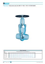
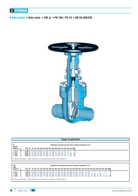
■ <strong>Gate</strong> <strong><strong>valve</strong>s</strong> ■ <strong>Gate</strong> <strong>valve</strong> ■ <strong>700</strong> <strong>JJ</strong> ■ <strong>PN</strong> <strong>160</strong> / <strong>PD</strong> <strong>18</strong> ■ <strong>DN</strong> 50-300/250<br />
Range of application<br />
FL- Admissible operating pressure [bar] at design temperature [°C] 1)<br />
Version<br />
Material <strong>PN</strong> -10 20 120 150 200 250 300 350 400 450 500 510 520 530 540 550<br />
1.5415 <strong>160</strong> <strong>160</strong> <strong>160</strong> <strong>160</strong> <strong>160</strong> <strong>160</strong> <strong>160</strong> 139 125 1<strong>18</strong> 112 72 55 43 35<br />
1.7335 <strong>160</strong> <strong>160</strong> <strong>160</strong> <strong>160</strong> <strong>160</strong> <strong>160</strong> <strong>160</strong> <strong>160</strong> 153 146 139 1<strong>18</strong> 100 79 62 46 35<br />
1.7383 <strong>160</strong> <strong>160</strong> <strong>160</strong> <strong>160</strong> <strong>160</strong> <strong>160</strong> <strong>160</strong> <strong>160</strong> 153 146 139 1<strong>18</strong> 100 79 70 61 52<br />
1) Operating temperature = design temperature minus temperature surcharge acc. to DIN regulations.<br />
BW- Admissible operating pressure [bar] at design temperature [°C] 1)<br />
Ends<br />
Material <strong>PD</strong> 20 50 100 120 150 200 250 300 350 400 420 430 440 460 470 480 490 500 510 520 530 540 550 560 570 580 590 600<br />
1.5415 <strong>18</strong> 258 246 229 219 204 <strong>18</strong>5 170 146 141 136 134 133 132 130 129 128 112 88 67 53 42<br />
1.7335 <strong>18</strong> 258 249 234 228 219 205 194 <strong>18</strong>0 170 161 156 155 153 150 149 148 147 133 112 89 72 58 46 37 30<br />
1.7383 <strong>18</strong> 258 250 239 233 224 210 205 194 <strong>18</strong>0 170 166 164 162 159 156 155 153 131 115 100 88 76 66 56 50 43 37 33<br />
1) Operating temperature = design temperature minus temperature surcharge acc. to DIN regulations.<br />
56<br />
6100.1.11.09<br />
Technical alterations reserved
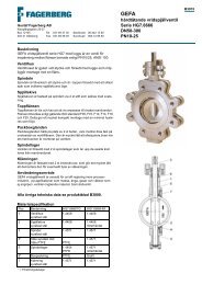
■ <strong>Gate</strong> <strong><strong>valve</strong>s</strong> ■ <strong>Gate</strong> <strong>valve</strong> ■ <strong>700</strong> <strong>JJ</strong> ■ <strong>PN</strong> <strong>160</strong> / <strong>PD</strong> <strong>18</strong> ■ <strong>DN</strong> 50-300/250<br />
Standard features<br />
Media<br />
■<br />
■<br />
■<br />
■<br />
■<br />
■<br />
Die-forged body<br />
Flexible wedge<br />
Incorporated seats<br />
Outside screw<br />
Yoke sleeve with needle bearings<br />
Universal <strong>valve</strong> head for mounting actuators<br />
Pressure and temperature ratings<br />
Depending on the material the gate <strong><strong>valve</strong>s</strong> are suitable<br />
for water, gas, oil and other non aggressive media<br />
Fields of application<br />
Chemical industries, power plants, ship building and<br />
other<br />
■ Pressure rating BW up to 233 bar (<strong>PD</strong> <strong>18</strong>)<br />
■ Pressure rating FL up to <strong>160</strong> bar<br />
■ Temperature ratings up -10° C to +600° C<br />
Materials<br />
■ 1.5415<br />
■ 1.7335<br />
■ 1.7383<br />
Further materials, e.g. F92 on request<br />
Design Highlights<br />
Benefits<br />
■<br />
Die-forged <strong>valve</strong> body with incorporated seats<br />
■<br />
Free from porosity and shrink holes<br />
■<br />
Seats and wedge faced with stellite<br />
■<br />
Best possible sliding performance, minimum wear<br />
■<br />
Hammer head connection between wedge and stem<br />
■<br />
The wedges are able to move parallel to the axis of the<br />
pipeline within the guiding groove. This protects the<br />
stem against bending moments<br />
■<br />
Gland ring and gland flange in two separate pieces<br />
■<br />
Damage to the stem by irregular tightening of gland<br />
bolts is avoided<br />
■<br />
Yoke sleeve supported at the top and at the bottom by<br />
means of needle bearings (axial type)<br />
■<br />
To minimize the expenditure of effort when opening<br />
and closing the <strong>valve</strong><br />
■<br />
Valve head equipped with dirt scrapers below and<br />
above the bearings<br />
■<br />
To protect against dirt and to avoid the loss<br />
of lubricants<br />
Technical alterations reserved 6100.1.11.09 57
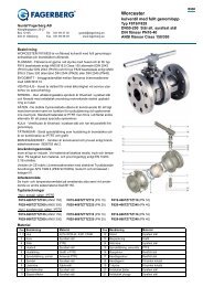
■ <strong>Gate</strong> <strong><strong>valve</strong>s</strong> ■ <strong>Gate</strong> <strong>valve</strong> ■ <strong>700</strong> <strong>JJ</strong> ■ <strong>PN</strong> <strong>160</strong> / <strong>PD</strong> <strong>18</strong> ■ <strong>DN</strong> 50-300/250<br />
Stroke<br />
610<br />
613<br />
600<br />
605<br />
540<br />
553<br />
590<br />
542<br />
510<br />
511<br />
552<br />
464<br />
440<br />
462<br />
430<br />
420 421<br />
412<br />
200<br />
190<br />
170<br />
410<br />
<strong>160</strong><br />
400<br />
100<br />
360<br />
361<br />
363<br />
58<br />
6100.1.11.09<br />
Technical alterations reserved
■ <strong>Gate</strong> <strong><strong>valve</strong>s</strong> ■ <strong>Gate</strong> <strong>valve</strong> ■ <strong>700</strong> <strong>JJ</strong> ■ <strong>PN</strong> <strong>160</strong> / <strong>PD</strong> <strong>18</strong> ■ <strong>DN</strong> 50-300/250<br />
Materials<br />
Pos. Component 1.5415 (42) 1.7335 (44) 1.7383 (45)<br />
100 Body 1.5415 1) 1.7383/1.7335 1) 1.7383 1)<br />
<strong>160</strong> grooved with Grooved with Grooved with<br />
4Gasket graphite layer graphite layer graphite layer<br />
170 Stud 1.7709 1.7709 2) 1.7709 2)<br />
<strong>18</strong>9 Expansion shaft -- 1.7709 2) 1.7709 2)<br />
190 Hexagonal nut 1.7258 1.7258 1.7258<br />
200 Bonnet 1.7383 1.7383 1.7383<br />
360/361 4Double disc 1.7383 1) 1.7383 1) 1.7383 1)<br />
363 4Pressure piece 1.4122 1.4122 1.4122<br />
400 4Stem 1.4923 1.4923 1.4923<br />
410 Back seat bushing 1.4006 1.4006 1.4006<br />
412 Bottom ring 1.07<strong>18</strong> 1.07<strong>18</strong> 1.07<strong>18</strong><br />
420 4Packing Graphite Graphite Graphite<br />
430 Gland ring 1.5415 1.5415 1.5415<br />
440 Gland flange 1.5415 1.5415 1.5415<br />
450 Rivet pin 1.7258 1.7258 1.7258<br />
462 Eye bolt 1.7709 1.7709 1.7709<br />
464 Hexagonal nut 1.7258 1.7258 1.7258<br />
510 4Yoke sleeve CW 713 R CW 713 R CW 713 R<br />
511 4Roller bearing WLSt WLSt WLSt<br />
540 Flange 1.0425 1.0460 1.0460<br />
542 Headcap screw 8.8 8.8 8.8<br />
552/553 4Gasket NBR Viton Viton<br />
590 Grease nipple 5.8 5.8 5.8<br />
600 Handwheel St St St<br />
605 Key 1.0060 1.0060 1.0060<br />
610 Hexagonal pipe nut St St St<br />
613 Screw pin 45H 45H 45H<br />
4Spare parts<br />
1) Welded on with Stellite<br />
2) Working temperature > 550° C = Material 1.4923<br />
Dimensions/mm<br />
Weights/kg and Kvs-values<br />
<strong>DN</strong> L H Stroke D<br />
50 300 490 80 350<br />
65/50 360 490 80 350<br />
80 390 610 105 400<br />
100 450 695 130 500<br />
125/100 525 695 130 500<br />
150 600 890 <strong>18</strong>5 800<br />
200 750 1090 235 1000<br />
250 900 1275 280 1000<br />
300/250 1050 1275 280 1000<br />
Kvs<br />
<strong>DN</strong> Flange BW (m3/h)<br />
50 60 45 228<br />
65/50 66 52<br />
80 116 100 565<br />
100 148 125 930<br />
125/100 165 130<br />
150 320 270 1995<br />
200 610 520 3458<br />
250 1050 930 5367<br />
300/250 1<strong>18</strong>0 980 5041<br />
Technical alterations reserved 6100.1.11.09 59