Catalog Q410
Catalog Q410
Catalog Q410

Create successful ePaper yourself
Turn your PDF publications into a flip-book with our unique Google optimized e-Paper software.
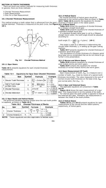
SECTION 10 TOOTH THICKNESS<br />
There are direct and indirect methods for measuring tooth thickness.<br />
In general, there are three methods:<br />
¥ Chordal Thickness Measurement<br />
¥ Span Measurement<br />
¥ Over Pin or Ball Measurement<br />
10.1 Chordal Thickness Measurement<br />
This method employs a tooth caliper that is referenced from the gear's<br />
outside diameter. Thickness is measured at the pitch circle, See Figure<br />
10-1.<br />
10.1.3 Helical Gears<br />
The chordal thickness of helical gears should be<br />
measured on the normal surface basis as shown in Table<br />
10-3. Table 10-4 presents the equations for chordal<br />
thickness of helical gears in the radial system.<br />
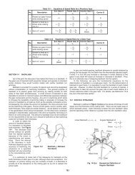
10.1.4 Bevel Gears<br />
Table 10-5 shows the equations of chordal thickness<br />
for a Gleason straight bevel gear.<br />
Table 10-6 presents equations for chordal thickness of<br />
a standard straight bevel gear.<br />
If a standard straight bevel gear is cut by a Gleason<br />
straight bevel cutter, the tooth angle should be adjusted<br />
according to:<br />
tooth angle (º) = 180º ( s + h 1 tanα) (10-1)<br />
πR e 2<br />
This angle is used as a reference in determining the<br />
circular tooth thickness, s, in setting up the gear cutting<br />
machine.<br />
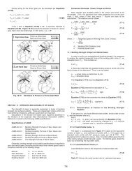
Table 10-7 presents equations for chordal thickness of<br />
a Gleason spiral bevel gear.<br />
The calculations of circular thickness of a Gleason spiral<br />
bevel gear are so complicated that we do not intend to go<br />
further in this presentation.<br />
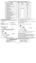
10.1.1 Spur Gears<br />
Table 10-1 presents equations for each chordal thickness<br />
measurement.<br />
10.1.2 Spur Racks and Helical Racks<br />
The governing equations become simple since the rack tooth profile<br />
is trapezoid, as shown in Table 10-2.<br />
10.1.5 Worms and Worm Gears<br />
Table 10-8 presents equations for chordal thickness of<br />
axial module worms and worm gears.<br />
Table 10-9 contains the equations for chordal<br />
thickness of normal module worms and worm gears.<br />
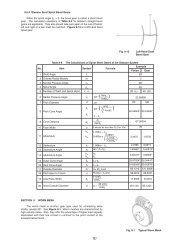
10.2 Span Measurement Of Teeth<br />
Span measurement of teeth, S m , is a measure over a<br />
number of teeth, Z m , made by means of a special tooth<br />
thickness micrometer. The value measured is the sum of<br />
normal circular tooth thickness on the base circle, S bn<br />
and normal pitch, Pen (Z m - 1).<br />
10.2.1 Spur and Internal Gears<br />
The applicable equations are presented in Table<br />
10-10.<br />
Figure 10-4 shows the span measurement of a spur<br />
gear. This measurement is on the outside of the teeth.<br />
For internal gears the tooth profile is opposite to that of<br />
the external spur gear. Therefore, the measurement is<br />
between the inside of the tooth profiles.<br />
10.2.2 Helical Gears<br />
Tables 10-11 and 10-12 present equations for span<br />
measurement of the normal and the radial systems,<br />
respectively, of helical gears.<br />
366
367
368
369
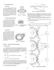
The procedure for measuring a rack with a pin or a ball is as<br />
shown in Figure 10-9 by putting pin or ball in the tooth<br />
space and using a micrometer between it and a reference<br />
surface. Internal gears are similarly measured, except that<br />
the measurement is between the pins. See Figure 10-10.<br />
Helical gears can only be measured with balls. In the case of<br />
a worm, three pins are used, as shown in Figure 10-11. This<br />
is similar to the procedure of measuring a screw thread. All<br />
these cases are discussed in detail in the following sections.<br />
Note that gear literature uses "over pins" and "over wires<br />
terminology interchangeably. The "over wires" term is often<br />
associated with very fine pitch gears because the diameters<br />
are accordingly small<br />
There is a requirement of a minimum<br />
blank width to make a helical gear<br />
span measurement. Let b min be the<br />
minimum value for blank width. See<br />
Figure 10-5. Then<br />
b min = S m sinβ b + ∆b (10-5)<br />
where β b is the helix angle at the<br />
base cylinder,<br />
β b = tan -1 (tanβ cos αt )<br />
= sin -1 (sinβ cos αn ) (10-6)<br />
From the above, we can determine<br />
that ∆b > 3 mm to make a stable<br />
measurement of S m<br />
10.3 Over Pin (Ball) Measurement<br />
As shown in Figures 10-6 and 10-7, measurement is made<br />
over the outside of two pins that are inserted in diametrically<br />
opposite tooth spaces, for even tooth number gears; and as close<br />
as possible for odd tooth number gears.<br />
10.3.1 Spur Gears<br />
In measuring a<br />
gear, the size of the<br />
pin must be such that<br />
the over pins<br />
measurement is<br />
larger than the gear's<br />
outside diameter. An<br />
ideal value is one that<br />
would place the point<br />
of contact (tangent<br />
point) of pin and<br />
tooth profile at the<br />
pitch radius.<br />
However, this is not a<br />
necessary<br />
requirement.<br />
Referring to Figure<br />
10-8, following are<br />
the equations for<br />
calculating the over<br />
pins measurement for a specific tooth thickness, s, regardless<br />
of where the pin contacts the tooth profile:<br />
For even number of teeth:<br />
d m = d cosφ + d p (10-7)<br />
cosφ 1<br />
For odd number of teeth:<br />
d m = d cosφ cos( 90º) + d P (10-8)<br />
cosφ 1 Z<br />
where the value of φ 1 is obtained from:<br />
invφ 1 = S + invφ + d P - π (10-9)<br />
d dcosφ Z<br />
When tooth thickness, s, is to be calculated from a known<br />
over pins measurement, dm, the above equations can be<br />
manipulated to yield:<br />
s = d( π + invφ c - invφ - d P ) (10-10)<br />
Z<br />
d cosφ<br />
where<br />
Cosφ c = d cosφ (10-11)<br />
2R c<br />
For even number of teeth:<br />
R c = d m - d P (10-12)<br />
2<br />
370
For odd number of teeth:<br />
(10-13)<br />
In measuring a standard gear, the size of the pin must meet<br />
the condition that its surface should have the tangent point at<br />
the standard pitch circle. While, in measuring a shifted gear, the<br />
surface of the pin should have the tangent point at the d + 2xm<br />
circle. The ideal diameters of pins when calculated from the<br />
equations of Table 10-13 may not be practical. So, in practice,<br />
we select a standard pin diameter close to the ideal value. After<br />
the actual diameter of pin d P is determined, the over pin<br />
measurement d m can be calculated from Table 10-14.<br />
Table 10-15 is a dimensional table under the condition of<br />
module m = 1 and pressure angle α = 20º with which the pin<br />
has the tangent point at d+ 2xm circle.<br />
10.3.2 Spur Racks and Helical Racks<br />
In measuring a rack,<br />
the pin is ideally<br />
tangent with the tooth<br />
flank at the pitch line.<br />
The equations in Table<br />
10-16 can, thus, be<br />
derived. In the case of<br />
a helical rack, module<br />
m, and pressure angle<br />
a, in Table 10-16, can<br />
be substituted by<br />
normal module, m n ,<br />
and normal pressure<br />
angle, a n , resulting in<br />
Table 10-16A.<br />
10.3.3 Internal Gears<br />
As shown in Figure<br />
10-10, measuring an<br />
internal gear needs a<br />
proper pin which has<br />
its tangent point at d<br />
+ 2xm circle. The<br />
equations are in Table<br />
10-17 for obtaining<br />
the ideal pin diameter.<br />
The equations for<br />
calculating the<br />
between pin<br />
measurement, dm1<br />
are given in Table<br />
10-18.<br />
Table 10-19 lists ideal pin diameters for standard and profile<br />
shifted gears under the condition of module m = 1 and pressure<br />
angle α = 20º, which makes the pin tangent to the pitch circle d<br />
+ 2xm.<br />
10.3.4 Helical Gears<br />
The ideal pin that makes contact at the d + 2x n m n pitch circle<br />
of a helical gear can be obtained from the same above<br />
equations, but with the teeth number z substituted by the<br />
equivalent (virtual) teeth number Z v .<br />
Table 10-20 presents equations for deriving over pin<br />
diameters.<br />
Table 10-21 presents equations for calculating over pin<br />
measurements for helical gears in the normal system.<br />
Table 10-22 and Table 10-23 present equations for calculating<br />
pin measurements for helical gears in the radial (perpendicular<br />
to axis) system.<br />
10.3.5 Three Wire Method of Worm Measurement<br />
The teeth profile of Type lll<br />
worms which are most popular<br />
are cut by standard cutters<br />
with a pressure angle α c =<br />
20º. This results in the normal<br />
pressure angle of the worm<br />
being a bit smaller than 20º.<br />
The equation below shows how<br />
to calculate a Type lll worm in<br />
an AGMA system.<br />
(10-14)<br />
where:<br />
r = Worm Pitch Radius<br />
r c = Cutter Radius<br />
Z w = Number of Threads<br />
γ = Lead Angle of Worm<br />
The exact equation for a three wire method of Type lll worm is<br />
not only difficult to comprehend, but also hard to calculate<br />
precisely. We will introduce two approximate calculation<br />
methods here:<br />
(a) Regard the tooth profile of the worm as a linear tooth profile<br />
of a rack and apply its equations. Using this system, the three<br />
wire method of a worm can be calculated by Table 10-24.<br />
These equations presume the worm lead angle to be very<br />
small and can be neglected. Of course, as the lead angle gets<br />
larger, the equations' error gets correspondingly larger. If the<br />
lead angle is considered as a factor, the equations are as in<br />
Table 10-25.<br />
(b) Consider a worm to be a helical gear.<br />
This means applying the equations for calculating over pins<br />
measurement of helical gears to the case of three wire method<br />
of a worm. Because the tooth profile of Type Ill worm is not an<br />
involute curve, the method yields an approximation. However,<br />
the accuracy is adequate in practice.<br />
Tables 10-26 and 10-27 contain equations based on the<br />
axial system. Tables 10-28 and 10-29 are based on the<br />
normal system.<br />
Table 10-28 shows the calculation of a worm in the normal<br />
module system. Basically, the normal module system and the<br />
axial module system have the same form of equations. Only the<br />
notations of module make them different.<br />
10.4 Over Pins Measurements For Fine Pitch<br />
Gears With Specific Numbers Of Teeth<br />
Table 10-30 presents measurements for metric gears. These<br />
are for standard ideal tooth thicknesses. Measurements can be<br />
adjusted accordingly to backlash allowance and tolerance; i.e.,<br />
tooth thinning.<br />
371
372
373
374
375
376
377
378
379
380
381