T 3 - Quality Transmission Components
T 3 - Quality Transmission Components
T 3 - Quality Transmission Components

You also want an ePaper? Increase the reach of your titles
YUMPU automatically turns print PDFs into web optimized ePapers that Google loves.
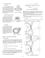
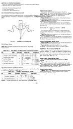
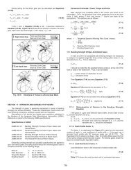
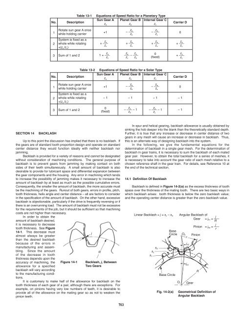
Circular backlash j t has a relation with angular backlash j θ , as follows:360j θ = j t –––– (degrees) (14-6)πdhave the following relationships:j n = j t cosα⎫ ⎪j t ⎬ (14-11)j r ' = ––––––⎪2tanα⎭14.2.1 Backlash Of A Spur Gear MeshFrom Figure 14-4 we can derive backlash of spur mesh as:j n = j t cosα⎫ ⎪j t ⎬ (14-7)j r = –––––⎪2tanα⎭j r1αj t ––2j t –––––2 tanαj n ––214.2.2 Backlash Of Helical Gear Meshδ 1j r2The helical gear has two kinds of backlash when referring to the toothspace. There is a cross section in the normal direction of the tooth surfacen, and a cross section in the radial direction perpendicular to the axis, t.j ntj nnα nj ttj tnα tβj nn = backlash in thedirection normalto the tooth surfacej nt = backlash in thecircular directionin the cross sectionnormal to thetoothj tn = backlash in thedirection normalto the tooth surfacein the crosssection perpendicularto theaxisFig. 14-6Backlash of Straight Bevel Gear MeshThe radial backlash in the plane of axes can be broken down intothe components in the direction of bevel pinion center axis, j r1 , and in thedirection of bevel gear center axis, j r2 .j t⎫j r1 = ––––––––––2tanα sinδ 1 ⎪ ⎬ (14-12)j tj r2 = ––––––––––⎪2tanα cosδ 1⎭14.2.4 Backlash Of A Spiral Bevel Gear MeshFigure 14-7 delineates backlash for a spiral bevel gear mesh.j ttj ntFig. 14-7 Backlash of Spiral Bevel Gear MeshFig. 14-5 Backlash of Helical Gear MeshThese backlashes have relations as follows:In the plane normal to the tooth:j nn = j nt cosα n (14-8)On the pitch surface:2 j rj tt = backlash in thecircular directionperpendicular tothe axisβ mj ntδ 1j ttj ntα nj r1j nnα xj tt ––2jtn––2j tt –––––2 tanα tj nt = j tt cos β (14-9)j r2In the plane perpendicular to the axis:j tn = j tt cosα t⎫ ⎪j tt ⎬ (14-10)j r = –––––⎪2tanα t⎭In the tooth space cross section normal to the tooth:14.2.3 Backlash Of Straight Bevel Gear MeshFigure 14-6 expresses backlash for a straight bevel gear mesh.In the cross section perpendicular to the tooth of a straight bevel gear,circular backlash at pitch line j t , normal backlash j n and radial backlash j r 'j nn = j nt cosα n (14-13)On the pitch surface:j nt = j tt cosβ m (14-14)T65
In the plane perpendicular to the generatrix of the pitch cone:j tn = j tt cosα t⎫ ⎪j tt ⎬ (14-15)j r ' = –––––⎪2tanα t⎭The radial backlash in the plane of axes can be broken down intothe components in the direction of bevel pinion center axis, j r1 , and in thedirection of bevel gear center axis, j r2 .j tt⎫j r1 = –––––––––2tanα t sinδ 1 ⎪ ⎬ (14-16)j ttj r2 = –––––––––⎪2tanα t cosδ 1⎭Let the backlash on the center distance direction be j r , then:j t 0.2j r = ––––– = ––––––– = 0.27472tanα 2tan20°These express the relationship among several kinds of backlashes. Inapplication, one should consult the JIS standard.There are two JIS standards for backlash – one is JIS B 1703-76 forspur gears and helical gears, and the other is JIS B 1705-73 for bevel gears.All these standards regulate the standard backlashes in the direction of thepitch circle j t or j tt . These standards can be applied directly, but the backlashbeyond the standards may also be used for special purposes. When writingtooth thicknesses on a drawing, it is necessary to specify, in addition, thetolerances on the thicknesses as well as the backlash. For example:2 j r– 0.050Circular tooth thickness 3.141 – 0.10014.2.5 Backlash Of Worm Gear Meshj tt1j tt2j tt1Backlash 0.100 ... 0.200Figure 14-8 expresses backlash for a worm gear mesh.14.4 Gear Train And Backlashj tt2α x2 j rj ntγj tn1α tj tn2Fig. 14-8 Backlash of Worm Gear MeshGear 4Gear 3On the pitch surface of a worm:(z 4 , d 4 )(z 3 , d 3 )j nt = j tt1 sinγj nt = j tt2 cosγ ⎪ ⎬ (14-17)j tt2tanγ = –––⎪⎭j tt1In the cross section of a worm perpendicular to its axis:j tn1 = j tt1 cosα t⎫ ⎪j tt1 ⎬ (14-18)j r = –––––⎪2tanα t⎭⎫ ⎪⎪The discussions so far involved a single pair of gears. Now, we aregoing to discuss two stage gear trains and their backlash. In a two stagegear train, as Figure 14-9 shows, j 1 and j 4 represent the backlashes of firststage gear train and second stage gear train respectively.If number one gear were fixed, then the accumulated backlash onnumber four gear j tT4 would be as follows:d 3 jtT4 = j 1 ––– + j 4 (14-20)d 2Gear 2(z 2 , d 2 )Gear 1(z 1 , d 1 )In the plane perpendicular to the axis of the worm gear:j tn2 = j tt2 cosα x⎫ ⎪j tt2 ⎬ (14-19)j r = –––––⎪2tanα x⎭14.3 Tooth Thickness And BacklashThere are two ways to generate backlash. One is to enlarge the centerdistance. The other is to reduce the tooth thickness. The latter is muchmore popular than the former. We are going to discuss more about the wayof reducing the tooth thickness. In SECTION 10, we have discussed thestandard tooth thickness s. In the meshing of a pair of gears, if the tooththickness of pinion and gear were reduced by ∆s 1 and ∆s 2 , they wouldgenerate a backlash of ∆s 1 + ∆s 2 in the direction of the pitch circle.Let the magnitude of ∆s 1 , ∆s 2 be 0.1. We know that α = 20°, then:j t = ∆s 1 + ∆s 2 = 0.1 + 0.1 = 0.2Fig. 14-9Overall Accumulated Backlash ofTwo Stage Gear TrainThis accumulated backlash can be converted into rotation in degrees:360j θ = j tT4 ––––– (degrees) (14-21)π d 4The reverse case is to fix number four gear and to examine theaccumulated backlash on number one gear j tT1 .d 2 jtT1 = j 4 ––– + j 1 (14-22)d 3This accumulated backlash can be converted into rotation in degrees:j360θ = j tT1 –––– (degrees) (14-23)π d 1We can convert it into the backlash on normal direction:j n = j t cosα = 0.2cos20° = 0.1879T66
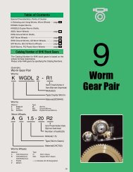
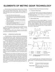
14.5 Methods Of Controlling BacklashIn order to meet special needs, precision gears are used morefrequently than ever before. Reducing backlash becomes an importantissue. There are two methods of reducing or eliminating backlash – one astatic, and the other a dynamic method.The static method concerns means of assembling gears and thenmaking proper adjustments to achieve the desired low backlash. Thedynamic method introduces an external force which continually eliminatesall backlash regardless of rotational position.14.5.1 Static MethodThis involvesadjustment of eitherthe gear's effectivetooth thickness or themesh center distance.These two independentadjustments can SizeGearbe used to producefour possible combinationsas shown in Table 14-2.FixedAdjustableTable 14-2Center DistanceFixedCase IBy design, center distance and tooth thickness are such that theyyield the proper amount of desired minimum backlash. Center distanceand tooth thickness size are fixed at correct values and require precisionmanufacturing.Case IIWith gears mounted on fixed centers, adjustment is made to theeffective tooth thickness by axial movement or other means. Three mainmethods are:1. Two identical gears are mounted so that one can be rotated relativeto the other and fixed. See Figure 14-10a. In this way, theeffective tooth thickness can be adjusted to yield the desired lowbacklash.2. A gear with a helix angle such as a helical gear is made in two halfthicknesses. One is shifted axially such that each makes contactwith the mating gear on the opposite sides of the tooth. See Figure14-10b.3. The backlash of cone shaped gears, such as bevel and taperedtooth spur gears, can be adjusted with axial positioning. A duplexlead worm can be adjusted similarly. See Figure 14-10c.IIIAdjustableIIIIVCase IIICenter distance adjustment of backlash can be accomplished in twoways:1. Linear Movement –Figure 14-11a showsadjustment along theline-of-centers in astraight or parallelaxes manner. Aftersetting to the desiredvalue of backlash, thecenters are locked inplace.2. Rotary Movement –Figure 14-11b showsan alternate way ofachieving center distanceadjustmentby rotation of one ofthe gear centers bymeans of a swing armon an eccentric bushing.Again, once thedesired backlash settingis found, the positioningarm is locked.Case IVAdjustment of both center distance and tooth thickness is theoreticallyvalid, but is not the usual practice. This would call for needless fabricationexpense.14.5.2 Dynamic MethodsFor LargeAdjustment(b) Rotary MovementFig. 14-11(a) Parallel MovementFor SmallAdjustmentWays of DecreasingBacklash in Case IIIDynamic methods relate to the static techniques. However, theyinvolve a forced adjustment of either the effective tooth thickness or thecenter distance.1. Backlash Removal by Forced Tooth ContactThis is derived from static Case II. Referring to Figure 14-10a , aforcing spring rotates the two gear halves apart. This results in an effectivetooth thickness that continually fills the entire tooth space in all meshpositions.2. Backlash Removal by Forced Center Distance ClosingThis is derived from static Case III. A spring force is applied to closethe center distance; in one case as a linear force along the line-of-centers,and in the other case as a torque applied to the swing arm.(a) Rotary Adjustment(b) Parallel AdjustmentIn all of these dynamic methods, the applied external force should beknown and properly specified. The theoretical relationship of the forcesinvolved is as follows:F > F 1 + F 2 (14-24)where:F 1 = <strong>Transmission</strong> Load on Tooth SurfaceF 2 = Friction Force on Tooth SurfaceIf F < F 1 + F 2 , then it would be impossible to remove backlash. But ifF is excessively greater than a proper level, the tooth surfaces would beneedlessly loaded and could lead to premature wear and shortened life.Thus, in designing such gears, consideration must be given to not only theneeded transmission load, but also the forces acting upon the tooth surfacescaused by the spring load. It is important to appreciate that the springloading must be set to accommodate the largest expected transmissionforce, F 1 , and this maximum spring force is applied to the tooth surfacescontinually and irrespective of the load being driven.(c) Axial Adjustment3. Duplex Lead WormA duplex lead worm mesh is a special design in which backlash can beadjusted by shifting the worm axially. It is useful for worm drives in highFig. 14-10 Ways of Reducing Backlash in Case IIT67
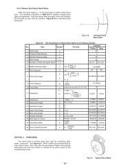
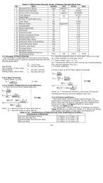
precision turntables and hobbing machines. Figure 14-12 presents thebasic concept of a duplex lead worm.The lead or pitch, p L and p R , on the two sides of the worm thread are notidentical. The example in Figure 14-12 shows the case when p R > p L . Toproduce such a worm requires a special dual lead hob.The intent of Figure 14-12 is to indicate that the worm tooth thicknessis progressively bigger towards the right end. Thus, it is convenient to adjustbacklash by simply moving the duplex worm in the axial direction.SECTION 15p R p R p R p Rp L p L p L p LFig. 14-12GEAR ACCURACYGears are one of the basic elements used to transmit power andposition. As designers, we desire them to meet various demands:1. Minimum size.2. Maximum power capability.3. Minimum noise (silent operation).4. Accurate rotation/position.To meet various levels of these demands requires appropriate degreesof gear accuracy. This involves several gear features.15.1 Accuracy Of Spur And Helical GearsThis discussion of spur and helical gear accuracy is based uponJIS B 1702 standard. This specification describes 9 grades of gearaccuracy – grouped from 0 through 8 – and four types of pitch errors:Single pitch error.Pitch variation error.Accumulated pitch error.Normal pitch error.Single pitch error, pitch variation and accumulated pitch errors are closelyrelated with each other.15.1.1 Pitch Errors of Gear TeethBasic Concepts of Duplex Lead Worm1. Single Pitch Error (f pt )The deviation between actual measured pitch valuebetween any adjacent tooth surface and theoreticalcircular pitch.2. Pitch Variation Error (f pu )Actual pitch variation between any two adjacent teeth.In the ideal case, the pitch variation error will be zero.3. Accumulated Pitch Error (F p )Difference between theoretical summation over anynumber of teeth interval, and summation of actual pitchmeasurement over the same interval.4. Normal Pitch Error (f pb )It is the difference between theoretical normal pitch andits actual measured value.The major element to influence the pitch errors is the runout of gearflank groove.Table 15-1 contains the ranges of allowable pitch errors of spur gearsand helical gears for each precision grade, as specified in JIS B 1702-1976.Table 15-1GradeJIS 012345678In the above table, W and W' are the tolerance units defined as:3The Allowable Single Pitch Error, Accumulated PitchError and Normal Pitch Error, µmSingle Pitch Errorf pt0.5W + 1.40.71W + 2.01.0W + 2.81.4W + 4.02.0W + 5.62.8W + 8.04.0W + 11.28.0W + 22.416.0W + 45.0W = √d + 0.65m (µm) (15-1)W' = 0.56 W + 0.25m (µm) (15-2)The value of allowable pitch variation error is k times the single pitcherror. Table 15-2 expresses the formula of the allowable pitch variationerror.Table 15-2 The Allowable Pitch Variation Error, µmSingle Pitch Error, f ptless than 55 or more, but less than 1010 or more, but less than 2020 or more, but less than 3030 or more, but less than 5050 or more, but less than 7070 or more, but less than 100100 or more, but less than 150more than 150Accumulated Pitch ErrorF p2.0W + 5.62.8W + 8.04.0W + 11.25.6W + 16.08.0W + 22.411.2W + 31.516.0W + 45.032.0W + 90.064.0W + 180.0Normal Pitch Errorf pbPitch Variation Error, f pu1.00f pt1.06f pt1.12f pt1.18f pt1.25f pt1.32f pt1.40f pt1.50f pt1.60f pt0.9W' + 1.41.25W' + 2.01.8W' + 2.82.5W' + 4.04.0W' + 6.36.3W' + 10.010.0W' + 16.020.0W' + 32.040.0W' + 64.0Figure 15-1 is an example of pitch errors derived from datameasurements made with a dial indicator on a 15 tooth gear. Pitchdifferences were measured between adjacent teeth and are plotted in thefigure. From that plot, single pitch, pitch variation and accumulated pitcherrors are extracted and plotted.20151050–5–10AB1 2 3 4 5 6 7 8 9 10 11 12 13 14 15 16Tooth Position NumberNOTE: A = Max. Single Pitch ErrorB = Max. Accumulated ErrorC = Max. Pitch Variation ErrorC= Indicator Reading= Single Pitch Error= Accumulate Pitch ErrorFig. 15-1Examples of Pitch Errors for a 15 Tooth GearT68