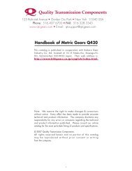

Create successful ePaper yourself
Turn your PDF publications into a flip-book with our unique Google optimized e-Paper software.
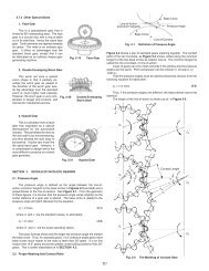
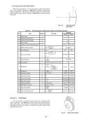
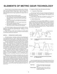
9.1 <strong>Worm</strong> MeshGeometryAlthough the wormtooth form can be of athe most popular isequivalent to a V-typescrew thread, as inFigure 9-1. The matingworm gear teeth have ahelical lead. (Note: Thename "worm wheel" isoften usedinterchangeably with"worm gear".) A centralsection of the mesh,taken through theworm's axis andperpendicular to theworm gear's axis, asshown in Figure 9-2, reveals a rack-type tooth of the worm,and a curved involute tooth form for the worm gear. However,the involute features are only true for the central section.Sections on either side of the worm axis reveal non-symmetricand non-involute tooth profiles. Thus, a worm gear mesh is nota true involute mesh. Also, for conjugate action, the centerdistance of the mesh must be an exact duplicate of that used ingenerating the worm gear.To increase the length-of-action, the worm gear is made of athroated shape to wrap around the worm.9.1.1 <strong>Worm</strong> Tooth Proportions<strong>Worm</strong> tooth dimensions, such as addendum, dedendum,pressure angle, etc., follow the same standards as those for spurand helical gears. The standard values apply to the centralsection of the mesh. See Figure 9-3a. A high pressure angle isfavored and in some applications values as high as 25º and 30ºare used.9.1.2 Number of ThreadsThe worm can be considered resembling a helical gear with ahigh helix angle. For extremely high helix angles, there is onecontinuous tooth or thread. For slightly smaller angles, there canbe two, three or even more threads. Thus, a worm ischaracterized by the number of threads, Z w9.1.3 Pitch Diameters, Lead and Lead AngleReferring to Figure 9-3:Pitch diameter of worm=d w = Z w P n (9-1)π sin γPitch diameter of worm gear=dg= Z g P n (9-2)π cos γwhere:Z w = number of threads of worm; Z g = number of teeth inworm gearP n = P x cos γ9.1.4 Center Distance9.2 Cylindrical <strong>Worm</strong> Gear Calculations(9-3)Cylindrical worms may be considered cylindrical type gearswith screw threads. Generally, the mesh has a 90º shaft angle.The number of threads in the worm is equivalent to the numberof teeth in a gear of a screw type gear mesh. Thus, a one-threadworm is equivalent to a one-tooth gear; and two-threadsequivalent to two-teeth, etc. Referring to Figure 9-4, for a leadangle y, measured on the pitch cylinder, each rotation of theworm makes the thread advance one lead.There are fourworm toothprofiles in JIS B1723, as definedbelow.Type l <strong>Worm</strong>:This worm toothprofile istrapezoid in theradial or axialplane.Type ll <strong>Worm</strong>:This tooth profileis trapezoidviewed in thenormal surface.Type Ill<strong>Worm</strong>:This wormis formed by acutter in whichthe tooth profileis trapezoid362
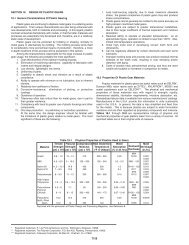
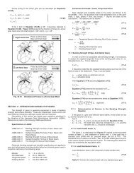
form viewed from the radial surface or axial plane set at the leadangle. Examples are milling and grinding profile cutters.Type lV <strong>Worm</strong>: This tooth profile is involute as viewed fromthe radial surface or at the lead angle. It is an involute helicoid,and is known by that name.Type lll worm is the most popular. In this type, the normalpressure angle α n has the tendency to become smaller than thatof the cutter, α cPer JIS, Type lll worm uses a radial module m t , and cutterpressure angle α c = 20º as the module and pressure angle. Aspecial worm hob is required to cut a Type lll worm gear.Standard values of radial module, m t , are presented in Table9-1.Table 9-1 Radial <strong>Module</strong> of Cylindrical <strong>Worm</strong> <strong>Gears</strong>1 1.25 1.60 2.00 2.50 3.15 4.00 5.006.30 8.00 10.00 12.50 16.00 20.00 25.00 -results when it is made byBecause the worm mesh couples nonparallel and nonintersecting using a hob that has anaxes, the radial surface of the worm, or radial cross section, is identical pitch diameter asthe same as the normal surface of the worm gear. Similarly, the that of the worm. Thisnormal surface of the worm is the radial surface of the worm crownless worm gear is verygear. The common surface of the worm and worm gear is the difficult to assemble correctly.normal surface. Using the normal module, m n is most popular. Proper tooth contact and aThen, an ordinary hob can be used to cut the worm gear. complete oil film are usuallyTable 9-2 presents the relationships among worm and worm not possible.gear radial surfaces, normal surfaces, axial surfaces, module, However, it is relativelypressure angle, pitch and lead.easy to obtain a crownedworm gear by cutting it with ahob whose pitch diameter isslightly larger than that of theworm. This is shown in Figure9-6. This creates teethcontact in the center regionwith space for oil filmformation.2. Recut With Hob Center Distance Adjustment.The first step is to cut theworm gear at standard centerdistance. This results in nocrowning. Then the worm gearis finished with the same hobby recutting with the hob axisshifted parallel to the wormgear axis by ±∆h. This resultsReference to Figure 9-4 can help the understanding of the in a crowning effect, shown inrelationships in Table 9-2. They are similar to the relations in Figure 9-7.Formulas (6-11) and (6-12) that the helix angle β besubstituted by (90º - γ) We can consider that a worm with leadangle γ is almost the same as a screw gear with helix angle (90º 3. Hob Axis Inclining ∆θ From Standard Position.- γ).9.2.1 <strong>Axial</strong> <strong>Module</strong> <strong>Worm</strong> <strong>Gears</strong>Table 9-3 presents the equations, for dimensions shown inFigure 9-5, for worm gears with axial module, m x and normalpressure angle α n = 20º.9.2.2 Normal <strong>Module</strong> System <strong>Worm</strong> <strong>Gears</strong>The equations for normal module system worm gears arebased on a normal module, m n and normal pressure angle, an =20º See Table 9-4.9.3 Crowning Of The <strong>Worm</strong> Gear ToothCrowning is critically important to worm gears (worm wheels)Not only can it eliminate abnormal tooth contact due to incorrectassembly, but it also provides for the forming of an oil film,which enhances the lubrication effect of the mesh. This canfavorably impact endurance and transmission efficiency of theworm mesh There are four methods of crowning worm gears:1. Cut <strong>Worm</strong> Gear With A Hob Cutter Of Greater PitchDiameter Than The <strong>Worm</strong>.A crownless worm gearIn standard cutting, the hob axis is oriented at the proper angleto the worm gear axis. After that, the hob axis is shifted slightlyleft and then right, ∆θ, in a plane parallel to the worm gear axis,to cut a crown effect on the worm gear tooth. This is shown inFigure 9-8.Only method 1 is popular. Methods 2 and 3 are seldom used.363
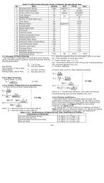
∇ Double-Threaded Right-Hand <strong>Worm</strong>Note 1: Diameter Factor, Q, means pitch diameter of worm, d1, over axial module, mxQ = d1mxNote 2: There are several calculation methods of worm outside diameter da2 besides those in Table 9-3.Note 3: The length of worm with teeth, b1, would be sufficient if:b1 = π mx(4.5+ 0.02z2)Note 4: Working blank width of worm gear be = 2mx (Q + 1)½. So the actual blank width of b ≥ be + 1.5mx would be enough.∇ Double-Threaded Right-Hand <strong>Worm</strong>Note: All notes are the same as those of Table 9-3.364
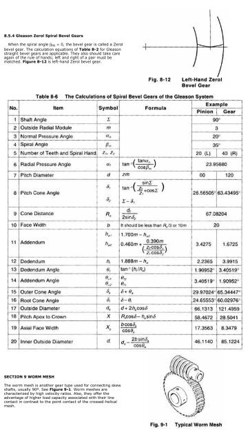
4. Use A <strong>Worm</strong> With A Larger Pressure Angle Than The<strong>Worm</strong> Gear.This is a very complex method, both theoretically andpractically. Usually, the crowning is done to the worm gear, butin this method the modification is on the worm. That is, tochange the pressure angle and pitch of the worm withoutchanging the pitch line parallel to the axis, in accordance withthe relationships shown in Equations 9-4:p x cosα x = p x 'cosα x ' (9-4)In order to raise the pressureangle from before change, α x 'to after change, α x , it isnecessary to increase the axialpitch, P x ' to a new value, P x perEquation (9-4). The amount ofcrowning is represented as thespace between the worm andworm gear at the meshing pointA in Figure 9-9. This amountmay be approximated by thefollowing equation:Amount of Crowning= k Px-Px' d 1 (9-5)Px' 2where:d 1 = Pitch diameter of wormk = Factor from Table 9-5 andFigure 9-10P x = <strong>Axial</strong> pitch after changep x '= <strong>Axial</strong> pitch before changeAn example of calculating worm crowning is shown in Table9-6.Because the theory and equations of these methods are socomplicated, they are beyond the scope of this treatment.Usually, all stock worm gears are produced with crowning.9.4 Self-Locking Of <strong>Worm</strong> MeshSelf-locking is a unique characteristic of worm meshes thatcan be put to advantage. It is the feature that a worm cannot bedriven by the worm gear. It is very useful in the design of someequipment, such as lifting, in that the drive can stop at anyposition without concern that it can slip in reverse. However, insome situations it can be detrimental if the system requiresreverse sensitivity, such as a servo-mechanism.Self-locking does not occur in all worm meshes, since itrequires special conditions as outlined here. In this analysis,only the driving force acting upon the tooth surfaces isconsidered without any regard to losses due to bearing friction,lubricant agitation, etc. The governing conditions are as follows:Let F u1 = tangential driving force of wormThen, F u1 = F n (cosα n sinγ - µ cos γ ) (9-6)where:α n = normal pressure angleγ = lead angle of wormµ = coefficient of frictionF n = normal driving force of wormIf F u1 > 0 then there is no self-locking effect at all. Therefore,F u1 ≤ 0 is the critical limit of self-locking.Let α n in Equation (9-6) be 20º, then the condition:F u1 ≤ 0 will become:(cos20º sinγ - µcosγ ) ≤ 0Figure 9-11 shows the critical limit of self-locking for lead angleγ and coefficient of friction µ. Practically, it is very hard to assessthe exact value of coefficient of friction µ. Further, the bearingloss, lubricant agitation loss, etc. can add many side effects.Therefore, it is not easy to establish precise self-lockingconditions. However, it is true that the smaller the lead angle γ,the more likely the self-locking condition will occur.365