Section 6. - Miter Gears - Quality Transmission Components
Section 6. - Miter Gears - Quality Transmission Components
Section 6. - Miter Gears - Quality Transmission Components
- No tags were found...

You also want an ePaper? Increase the reach of your titles
YUMPU automatically turns print PDFs into web optimized ePapers that Google loves.
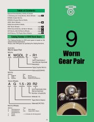
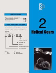
Table of ContentsSpecial Characteristics, Point of Cautionin Selecting and Using <strong>Miter</strong> <strong>Gears</strong>...........................page 194MMSG Ground Spiral <strong>Miter</strong> <strong>Gears</strong>.............................page 200SMSG Ground Spiral <strong>Miter</strong> <strong>Gears</strong>..............................page 202MMSA(B) Finished Bore Spiral <strong>Miter</strong> <strong>Gears</strong>.............page 204MMS Spiral <strong>Miter</strong> <strong>Gears</strong>...............................................page 206SMS Spiral <strong>Miter</strong> <strong>Gears</strong>...............................................page 208SMA(B)(C) Finished Bore <strong>Miter</strong> <strong>Gears</strong>......................page 212MM Carburized & Hardened <strong>Miter</strong> <strong>Gears</strong>..................page 216LM Sintered Metal <strong>Miter</strong> <strong>Gears</strong>...................................page 216SM <strong>Miter</strong> <strong>Gears</strong>.............................................................page 218SAM Angular <strong>Miter</strong> <strong>Gears</strong>............................................page 220SUM Stainless Steel <strong>Miter</strong> <strong>Gears</strong>...............................page 222PM Plastic <strong>Miter</strong> <strong>Gears</strong>................................................page 224DM Injection Molded <strong>Miter</strong> <strong>Gears</strong>...............................page 226BB Sintered Metal Bushings.......................................page 226Catalog Number of KHK Stock <strong>Gears</strong>The Catalog Number for KHK stock gears is based on thesimple formula listed below.Please order KHK gears by specifying the Catalog Numbers.6<strong>Miter</strong> <strong>Gears</strong>(Example)<strong>Miter</strong> <strong>Gears</strong>M MSG 2 - 20 RDirection of Spiral ( R )No. of teeth (20)Module (2)Type (Ground Spiral <strong>Miter</strong> Gear)Material (SCM415)MaterialS S45CM SCM415SU SUS303L SMF5040P MC901D Duracon(M90-44)TypeMMSMSGAM<strong>Miter</strong> <strong>Gears</strong>Spiral <strong>Miter</strong> <strong>Gears</strong>Ground Spiral <strong>Miter</strong> <strong>Gears</strong>Angular <strong>Miter</strong> <strong>Gears</strong>193
<strong>Miter</strong> <strong>Gears</strong>Wide Variety from High Precision to Commercial Grades !Characteristics<strong>Miter</strong> gears are a special class of bevel gears where the shafts intersect at 90° and the gear ratio is 1:1. KHK stock miter gears are available in two types,spiral and straight tooth, with high precision grade for demanding torques and speeds, and commercial grade for economical applications.■ Main Features of Stock <strong>Miter</strong> <strong>Gears</strong> OfferedThe following table lists the main features for easy selection.TypeCatalog No.ModuleNo. of teeth( ) denotes shafts angleMaterialHeattreatmentToothsurfacefinishPrecisionJIS B 1704SecondaryOperationsFeaturesSpiral <strong>Miter</strong> <strong>Gears</strong>MMSGSMSGMMSA(B) NOTE 1MMSSMSSMA(B)(C) NOTE 1MM2~42~51~102~51~81~82~520, 25, 3020, 25, 302020, 2520, 25, 3020, 25, 3020, 25SCM415S45CSCM415SCM415S45CS45CSCM415Carburizing NOTE 3Gear teethinductionhardenedOverallCarburizing NOTE 4Carburizing NOTE 3Gear teethinductionhardenedGear teetinductionhardenedCarburizing NOTE 3GroundGroundCutCutCutCutCut2244444△△×△△△△High strength, abrasion-resistant and compact forhigh speed & torque use.Reasonably priced ground gear, yet remachinableexcept for the gear teeth.Ready to use without performing secondaryoperations. Strong and abrasion resistant.Only teeth are induction hardened, allowing user toperform secondary operations elsewhere.Large numbers of teeth and modules are offered inthese affordable spiral miter gears.Usable without remachining, offered in 3 bore sizes.Compared to SM miters, these are stronger andless abrasive, and allow secondary operations.Straight <strong>Miter</strong> <strong>Gears</strong>LM NOTE 2SMSAMSUM0.8~1.51~81.5~31~32016, 20, 25, 3020 (45°, 60°, 120°)20, 25SMF5040(Equiv. to S45C)S45CS45CSUS303----SinteredCutCutCut5333○○○○Mass-produced, low cost sintered products. Smalland light weight.Popular straight miter for many uses.3 types are available for shafts at 45°, 60° and 120°.Suitable for food machinery due to SUS303’s rustresistantquality.PM1~420, 25MC901-Cut4○MC nylon products are light and can be usedwithout lubricant.DM0.5~1.520M90-44-Injectionmolded8△Injection molded, mass-produced products, suitablefor office machines.NOTE 1: The letters “B” and “C” at the end of catalog numbers designate sameitems except for changes in the bore and keyway sizes.NOTE 2: Sintered metal <strong>Miter</strong> <strong>Gears</strong> are manufactured by mixing powderedmetal and pressing them in a mold under heat to fuse, sizing andimpregnating with oil.NOTE 3: Even though the bore and the hub portions are masked during thecarburization and they can be modified, care should be exercisedsince the hardness is somewhat higher.NOTE 4: MMSA(B) spiral miter gears are carburized throughout so that they donot permit any secondary operations. However, the back surface ofB7 style gears is masked during the process so that it is possible todrill and pin on this surface.○ Possible △ Possible on some areas×Not possibleConiflexKHK utilizes Gleason Coniflex No. 104, 102 and 114 bevel gear generatingmachinery and is well-equipped for mass production of straight miter gears. Youcan count on an economically priced, stable supply of straight miter gears fromKHK.194Crowning
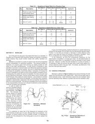
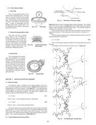
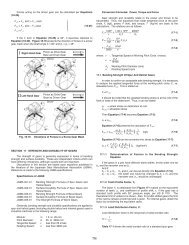
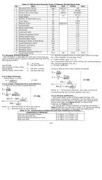
KHK Technical InformationSelection HintsPlease select the most suitable products by carefully considering the characteristics of items and contents of the product tables. It is alsoimportant to read all applicable “CAUTION” notes shown below before the final selection. Use of catalog numbers when ordering willsimplify and expedite the processing of your order.1. Caution in Selecting the Mating <strong>Gears</strong>1 Among KHK stock miter gears, there are products which arenot interchangeable even when the module and the number ofteeth are the same. Also, spiral miter gears require additionalconsideration since the right-hand mates with the left-hand spiralas shown in the table below.2 <strong>Miter</strong> gears are bevel gears with 1:1 gear ratio. Needless to say,they mate only with gears of the same module and number ofteeth. Also, since KHK’ uses the Gleason system, our mitergears may not mesh with those made by another company orcustom-made. It is best to order as a set.Difference between Gleason Straight Bevel <strong>Gears</strong> and Standard Straight Bevel <strong>Gears</strong>There are differences in the gear blank shapes between the twosystems. In the table below, we illustrate the differences in variousangles and dimensions for typical straight bevel gear pairs.Gleason Straight Bevel <strong>Gears</strong>Standard Straight Bevel <strong>Gears</strong>■ Spiral <strong>Miter</strong> ( ○ Allowable △ Allowable in certain cases × Not allowable)Catalog No.&Spiral handMMSG(L)SMSG(L)MMSA(B)-(L)MMS(L)SMS(L)CAUTION: Spiral miter gears are paired to the items with the same catalognumber except the last characters are “R” and “L”. For selectingitems in the " △ " category, please reconfirm with your nearest KHKdealer that the pair can work.■ Straight <strong>Miter</strong> ( ○ Allowable × Not allowable)Catalog No.SMA(B)(C)MMSMSUMPMDMLMSAMRight Hand (R)SMA(B)(C)○○○○○×××○○○○○×××MMSG(R)○××××○○○○○×××SMSG(R)×○×××○○○○○×××MMSA(B)(R)Left-Hand (L)MM SM SUM PM DM LM SAM○○○○○×××××○△△×××××○××MMS(R)××△○△××××××○×SMS(R)××△△○×××××××○Module m = 3, No. of teeth of pinion z1 = 20,Gear z2 = 40, Face width b = 22, Pressure angleα0 = 20°123*4*5*6*7*8*9d0δ0R0hkhfδkδrdkXGleason straight bevel system Standard straight bevel systemz1=20 z2=40 z1=20 z2=406026°34'4.0352.52930°29'24°24'67.21858.197120 60 12063°26' 26°34' 63°26'67.083 67.0831.9654.59965°36'59°31'121.75828.24229°08'23°22'65.36758.6583.003.7566°00'60°14'122.68327.317CAUTION: In items 4 through 9 (marked with *), dimesions and angles are differentin two systems.195
<strong>Miter</strong> <strong>Gears</strong>2. Caution in Selecting <strong>Gears</strong> Based on Gear StrengthThe gear strength values shown in the product pages werecomputed by assuming a certain application environment.Therefore, they should be used as reference only. Werecommend that each user computes their own values byapplying the actual usage conditions. The table belowcontains the assumptions established for these products inorder to compute gear strengths.Definition of bending strengthThe allowable bending strength of a gearis defined as the allowable tangentialforce at the pitch circle based on themutually allowable root stress of twomeshing gears under load.Definition of surface durabilityThe surface durability of a gear isdefined as the allowable tangential forceat the pitch circle, which permits theforce to be transmitted safely withoutincurring surface failure.■ Calculation of Bending Strength of <strong>Gears</strong>Example of the failure dueto insufficient bendingstrength.Example of the defacementdue to insufficient surfacedurability.Catalog No.ItemMMSGMMSMMMMSA(B)SMSGSMSSMA(B)(C)SMSAMSUMLMPMDMFormula NOTE 1No. of teeth of mating gearsRotationDurabilityImpact from motorFormula of bevel gears on bending strength (JGMA403-01)Same number of teeth100min -1 (600min -1 for MMSG & SMSG)Over 10 7 cyclesUniform loadThe Lewis formula-100min -1-Allowable bending stressImpact from loadDirection of loadAllowable bending stress at root σFlim NOTE 2Safety factor KR31.33kgf/mm 2 31.33kgf/mm 2 Uniform loadBidirectional14kgf/mm 2 12.67kgf/mm 2 7kgf/mm 21.21.15kgf/mm 2(40℃ with nolubricant)NOTE 3m0.5 4.5m0.8 4.0m1.0 3.5m1.5 1.8kgf/mm 2■ Calculation of Surface Durability (Except those in common with bending strength)Formula NOTE 1Kinematic viscosity of lubricantGear supportFormula of bevel gears on bending strength (JGMA404-01)100cSt (50℃ )Shafts & gear box have normal stiffness, and gears are supported on one endAllowable Hertz stress σHlim 166kgf/mm 2 166kgf/mm 2 90kgf/mm 2 49kgf/mm 2 41.3kgf/mm 2Safety factor CR1.15NOTE 1: The gear strength formula is based on JGMA(Japanese Gear Manufacturers Association)specifications, “MC Nylon Technical Data” byNippon Polypenco Limited and “Duracon GearData” by Polyplastic Co. The units of number ofrotations (min -1 ) and the the stress (kgf/mm 2 ) areadjusted to the units needed in the formula.NOTE 2: Since the load is bidirectional, the allowablebending stress at root σFlim, used in JGMA403-01 formula is set to 2/3 of the value.NOTE 3: The values of the allowable bending stressesfor DM m0.5 and m1.5 and the allowableroot bending stress for LM gears are our ownestimates.3. Caution with Regard to the Special Characteristics of <strong>Miter</strong> <strong>Gears</strong> 4. Other Points to Consider in the Selection Process1 MMSA(B) spiral miter gears are carburized throughout so that theydo not permit any secondary operations. However, the back surfaceof B7 style gears is masked during the process so that it is possible todrill and pin on this surface.2 The keyway sizes of MMSA(B) finished bore spiral miter gears aremade according to JIS B 1301, medium quality, but the final heattreating may cause some deformation.3 The bore of SMS spiral miter gears may somewhat be deformed dueto heat treatment and does not reach H7 tolerance.4 Due to the characteristics of the material, PM plastic miter gears’product quality may be affected by heat or moisture absorption.5 Items with black oxide finish are somewhat effective in resisting rustbut are not totally rustproof.6 SUM stainless steel miter gears use material which is especiallyresistant to rust but still is not 100% rustproof.7 The bore tolerance of DM injection molded miter gears is generally-0.05 to -0.10, but may be plus values at the central portion of thehole. Remachining the bore is not recommended since reworkingmay expose voids in the plastic.1 There are various footnotes to the product pages under the headingsof “CAUTION” and” NOTE”. Please consider them carefully whenselecting these products.2 There may be slight differences in color or shape of products shownin the photographs from the actual products.3 KHK reserves the right to make changes in specifications anddimensions without notice.4 KHK is ready to produce and supply custom order products. Whenyou require specific gears different from KHK Stock <strong>Gears</strong> pleasecontact our distributor for quotation. Also, please refer to page 16“KHK Custom Order Products”.196
KHK Technical InformationApplication HintsIn order to use KHK stock gears safely, carefully read theApplication Hints before proceeding. If there are questions or yourequire clarifications, please contact our technical department oryour nearest distributor.KHK CO., LTD. TECHNICAL DEPARTMENTPHONE: 81-48-254-1744 FAX: 81-48-254-1765E-mail export@khkgears.co.jp5 MMSA(B) spiral miter gears are carburized throughout, so thatno secondary operations can be performed (except B7 styleitems). For items with induction hardened teeth, such as SMSGand SMS series, the hardness is high near the tooth root. Whenmachining the front face, the machined area should be 4 to 6mmsmaller than the dimension, J.1. Caution on Performing Secondary Operations1 If you are reboring, it is important to pay special attention tolocating the center in order to avoid runout.2 The reference datum for gear cutting is the bore. Therefore, it isbest to use the bore for locating the center. If it is too difficult todo for small bores, the alternative is to use one spot on the boreand the runout of the side surface.3 If reworking using scroll chucks, we recommend the use of newor rebored jaws for improved precision. Please exercise cautionnot to crush the teeth by applying too much pressure. Anyscarring will cause noise during operation.Lathe Operations6 For tapping and keyway operations, see the examples givenin “1. Caution on Performing Secondary Operations” in KHKStock Spur Gear section. When cutting keyways, to avoid stressconcentration, always leave radii on corners.7 PM plastic miter gears are susceptible to changes due totemperature and humidity. Dimensions may change betweenduring and after remachining operations.8 When heat treating S45C products, it is possible to get thermalstress cracks. It is best to subject them to penetrant inspectionafterwards. While the teeth strength may increase four fold, theprecision of the gear will drop approximately one grade.4 Staring in August 2003, the tooling holes on the hub face of thespiral miter gears (except ground gears) module 2.5 and abovehave been eliminated. However, we may have some items instock with the hole.197
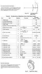
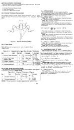
<strong>Miter</strong> <strong>Gears</strong>2. Points of Caution in Assembling1 Since miter gears are cone shaped, they produce axial thrustforces. Specifically with regard to spiral miter gears, thedirections of thrust change with the hand of spiral and thedirection of rotation. This is illustrated below. The bearingsmust be selected properly to be able to handle these thrustforces.ThrustThrustDriveDriveThrustThrust3 If a miter gear is mounted on a shaft far from the bearings, theshaft may bend. We recommend mounting bevel gears as closeto the bearings as possible. This is especially important sincemost miter gears are supported on one end. The bending ofshafts will cause abnormal noise and wear, and may even causefatigue failure of the shafts. Both shafts and bearings must bedesigned with sufficient strength.4 Due to the thrust load of miter gears, the gears, shafts andbearings have the tendency to loosen up during operation. <strong>Miter</strong>gears should be fastened to the shaft with keys and set screws,taper pins, step shafts, etc.5 When installing MMSA(B) finished bore spiral miter gears inB7 style (ring type), always secure the gears onto the mountingbase with taper pins to absorb the rotational loads. It isdangerous to secure with bolts only.Taper Tin pinThrustThrustGearThrustThrustMounting base2 KHK stock miter gears are designed such that, when assembledaccording to the specified mounting distance with a toleranceof H7~H8, the backlash shown in the table are obtained.Mounting distance error, offset error and shaft angle error mustbe minimized to avoid excessive noise and wear. Inaccurateassembly will lead to irregular noises and uneven wear. Variousconditions of teeth contact are shown below.Correct Tooth Contact● When assembled correctly, the contact will occur on both gearsin the middle of the flank and center of face width but somewhatcloser to the toe.■ Mounting Distance Error● When the mounting distance of thepinion is incorrect, the contact willoccur too high on the flank on onegear and too low on the other.Incorrect Tooth Contact■ Offset Error● When the pinion shaft is offset, thecontact surface is near the toe of onegear and near the heel of the other.■ Shaft Angle Error● When there is an angular error ofshafts, the gears will contact at thetoes or heels depending on whetherthe angle is greater or less than 90°.198
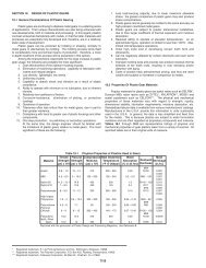
KHK Technical Information3. Notes on Starting Operations1 Before operating, check the following:● Are the gears firmly mounted on the shafts?● Have you eliminated uneven tooth contact?● Does the gear mesh have a proper amount of backlash?(Please avoid the condition of no backlash)● Is there sufficient lubrication?2 If the gears are exposed, install a safety cover for protection.3 Check the noise and vibration while the machine is in operationfor any unusual conditions. If an abnormality is encountered,recheck the gears and assembly conditions. Also, checklubrication after start-up. Sometimes, when the unit is initiallybeing operated, lubricating oil deteriorates rapidly.4. Other Points to Consider in Applications1 KHK products are individually packaged to avoid damages.Depending on how they are handled, it is still possible to deform orbreak them. It is important to exercise care in handling these parts.2 Check the products as they are being taken out of the boxes. If anyof them are rusted, scratched or dented, please return to the dealerwhere they were bought, for exchange.3 KHK cannot guarantee the precision of gears once the customerperforms a secondary operation on them.PRODUCT IMPROVEMENT ANNOUNCEMENTIn order to increase the gear strength of KHK standard <strong>Miter</strong><strong>Gears</strong>, starting in June 2004, the following changes have beenintroduced. During this transition, some of the specificationswill change.1. Applicable Series1 MMSG Ground Spiral <strong>Miter</strong> <strong>Gears</strong> –(30 Items)2 MMS Spiral <strong>Miter</strong> <strong>Gears</strong> – (20 Items)3 MM <strong>Miter</strong> <strong>Gears</strong> – (10 Items)2. Improvement DetailsIncrease in gear strength (Approximately 15% higherbending strength compared to previous one)3. Change in the specificationsHeat treatmentBeforeTeeth induction hardenedafter carburizingAfterCarburizing (bore & hub portion masked)Surface Treatment Black oxide No black OxideThe corner tips of the gear-teeth of KHK stock <strong>Miter</strong> <strong>Gears</strong> aremachine chamfered for safety and for prevention of damages.■ The chamfering of the corner gear tips for miter gear (unit: mm)Module0.5 up to 11 up to 2.5Outside edge R0.51.0Inside edge Rall burrs removed0.52.5 up to 52.01.0over 53.01.5Example of KHK Gear ApplicationsElectric components assembly line(<strong>Miter</strong> gears )Automatic packaging machine (Spur gears)(<strong>Miter</strong> gears - inset)199
MMSG Ground Spiral <strong>Miter</strong> <strong>Gears</strong> Modules2~4MMSG4-20RRM MMSG4-20Lm4 20B4 20 55 80 84.99 65 39.13 27.5MSG MMSG2-25RRm2 25B4 12 38 50 52.5 40 23.43 1<strong>6.</strong>25MMSG2-25LL■ Modules 2~4B3 ShapeCatalog No. Gear ratio Module No. of teeth Directionof spiralShapeAH7 B C D E F GMMSG2-20RRm2 20MMSG2-20LLB3 12 35 40 42.7 35 21.98 1<strong>6.</strong>35MMSG2.5-20RRm2.5 20MMSG2.5-20LLB3 14 42 50 53.2 45 28.63 21.6MMSG3-20RR1 m3 20MMSG3-20LLB3 16 52 60 63.99 50 30.78 21.99MMSG3.5-20RRm3.5 20MMSG3.5-20LLB4 20 50 70 74.53 55 32.45 22.26<strong>Miter</strong><strong>Gears</strong>MMSG2.5-25RMMSG2.5-25LMMSG3-25RMMSG3-25LMMSG3.5-25RMMSG3.5-25LMMSG4-25RMMSG4-25LMMSG2-30RMMSG2-30LMMSG2.5-30RMMSG2.5-30LMMSG3-30RMMSG3-30LMMSG3.5-30RMMSG3.5-30LMMSG4-30RMMSG4-30L11m2.5 25m3 25m3.5 25m4 25m2 30m2.5 30m3 30m3.5 30m4 30RLRLRLRLRLRLRLRLRLBore Hub dia. Pitch dia. Outside dia. Mounting distance Total length Crown to back lengthB4 16 45 62.5 65.54 50 29.57 20.27B4 20 55 75 78.78 60 35.6 24.39B4 25 65 87.5 91.81 70 41.65 28.41B4 28 75 100 104.7 80 47.8 32.35B4 14 45 60 62.42 50 29.27 21.21B4 16 55 75 78.04 60 34.08 24.02B4 20 65 90 93.61 70 40.25 2<strong>6.</strong>8B4 25 80 105 109.21 80 44.4 29.6B4 28 90 120 124.7 90 49.27 32.35CAUTION: A set of miter gears must be identical in module and number of teeth, but opposite in spiral hands.CAUTION: Dimensions of the outside diameter, the overall length and crown to back length are all theoretical values, and some differences will occur due to the cornerchamfering of the gear tips.200
Ground Spiral <strong>Miter</strong> <strong>Gears</strong>Precision gradeGear teethPressure angleHelix angleMaterialHeat treatmentJIS B 1704 grade 2Gleason20°35°SCM415Carburizing NOTE 1SpecificationsTooth hardnessSurface treatmentTooth surface finishDatum reference surfacefor gear grinding55~60HRCNOTE 1: The areas marked with on the diagram are masked duringthe carburizing and can be modified, even though the hardness issomewhat higher.—GroundBoreSecondary Operations Possible where masking for carburizingB4 ShapeHub width Length of bore Face width Holding surface dia. Allowable torque(N・m) NOTE2 Allowable torque(kgf・m) BacklashH I J K Bending strength Surface durability Bending strength Surface durability(mm)NOTE2: The allowable torques shown in the table are the calculated values according to the assumed usage conditions. Please see page 196 for more details.Weight(kg)12.5 20 9 24.54 15.6 21.7 1.59 2.21 0.05~0.11 0.1416 26 11 30.89 30.0 42.6 3.06 4.35 0.06~0.12 0.2616 27 14 34.4 53.8 77.6 5.48 7.91 0.07~0.13 0.4414 29 16 42.75 84.3 124 8.60 12.6 0.08~0.14 0.5017 35 18 49.08 125 185 12.7 18.9 0.10~0.16 0.7211 21 11 30.89 25.3 43.5 2.57 4.44 0.05~0.11 0.2014 26 14 37.4 49.9 87.6 5.09 8.94 0.06~0.12 0.4017 31 17 43.92 8<strong>6.</strong>8 155 8.85 15.8 0.07~0.13 0.7019 37 20 52.43 139 251 14.1 25.6 0.08~0.14 1.1022 42 23 58.95 192 353 19.6 3<strong>6.</strong>0 0.10~0.16 1.7015 26 12 38.06 35.4 72.9 3.61 7.43 0.05~0.11 0.3716 30 15 47.57 69.1 145 7.05 14.8 0.06~0.12 0.7718 36 20 55.43 128 274 13.0 27.9 0.07~0.13 1.3020 40 22 67.77 181 393 18.4 40.1 0.08~0.14 2.3022 44 25 77.29 268 593 27.4 60.5 0.10~0.16 3.20Catalog No.MMSG2-20RMMSG2-20LMMSG2.5-20RMMSG2.5-20LMMSG3-20RMMSG3-20LMMSG3.5-20RMMSG3.5-20LMMSG4-20RMMSG4-20LMMSG2-25RMMSG2-25LMMSG2.5-25RMMSG2.5-25LMMSG3-25RMMSG3-25LMMSG3.5-25RMMSG3.5-25LMMSG4-25RMMSG4-25LMMSG2-30RMMSG2-30LMMSG2.5-30RMMSG2.5-30LMMSG3-30RMMSG3-30LMMSG3.5-30RMMSG3.5-30LMMSG4-30RMMSG4-30L<strong>Miter</strong><strong>Gears</strong>MMSG201
SMSG Ground Spiral <strong>Miter</strong> <strong>Gears</strong> Modules2~5S SMSG5-20RRM m5 20B3 25 80 100 105.9 90 60.16 42.95SMSG5-20LLSG■ Modules 2~5B3 ShapeCatalog No. Gear ratio Module No. of teeth Directionof spiralShapeAH7 B C D E F GSMSG2-20RRm2 20SMSG2-20LLB3 12 34 40 42.4 37 24.75 18.2SMSG2.5-20RRm2.5 20SMSG2.5-20LLB3 14 42 50 52.94 48 32.42 24.47SMSG3-20RRm3 20B3 16 50 60 63.72 58 39.6 29.86SMSG3-20LL1SMSG3.5-20RRm3.5 20B3 20 60 70 74.47 65 43.81 32.23SMSG3.5-20LLSMSG4-20RRm4 20SMSG4-20LLB3 20 64 80 84.88 75 50.51 37.44<strong>Miter</strong><strong>Gears</strong>SMSG2-25RSMSG2-25LSMSG2.5-25RSMSG2.5-25LSMSG3-25RSMSG3-25LSMSG3.5-25RSMSG3.5-25LSMSG4-25RSMSG4-25LSMSG5-25RSMSG5-25LSMSG2-30RSMSG2-30LSMSG2.5-30RSMSG2.5-30LSMSG3-30RSMSG3-30LSMSG3.5-30RSMSG3.5-30LSMSG4-30RSMSG4-30L11m2 25m2.5 25m3 25m3.5 25m4 25m5 25m2 30m2.5 30m3 30m3.5 30m4 30RLRLRLRLRLRLRLRLRLRLRLBore Hub dia. Pitch dia. Outside dia. Mounting distance Total length Crown to back lengthB3 12 40 50 52.4 40 24.19 1<strong>6.</strong>2B3 16 50 62.5 65.54 50 30.24 20.27B3 20 60 75 78.77 60 37.57 24.39B3 25 70 87.5 91.81 70 42.98 28.41B3 28 80 100 104.7 80 49.14 32.35B3 28 100 125 130.86 100 60.59 40.43B3 12 45 60 62.42 50 29.27 21.21B3 16 60 75 78.04 62 3<strong>6.</strong>08 2<strong>6.</strong>02B3 20 70 90 93.61 75 45.25 31.8B3 25 90 105 109.21 85 49.4 34.6B3 28 100 120 124.71 95 54.28 37.35CAUTION: A set of miter gears must be identical in module and number of teeth, but opposite in spiral hands.CAUTION: Dimensions of the outside diameter, the overall length and crown to back length are all theoretical values, and some differences will occur due to the cornerchamfering of the gear tips.202
Ground Spiral <strong>Miter</strong> <strong>Gears</strong>SpecificationsPrecision gradeJIS B 1704 grade 2Tooth hardness48~53HRCGear teethGleasonSurface treatmentBlack oxide except Ground surfacePressure angleHelix angleMaterialHeat treatment20°35°S45CTeeth induction hardenedToth surface finishDatum reference surfacefor gear grindingGroundBoreSecondary Operations Possible except tooth areasHub width Length of bore Face width Holding surface dia. Allowable torque(N・m) NOTE1 Allowable torque(kgf・m) BacklashH I J K Bending strength Surface durability Bending strength Surface durability(mm)NOTE 1: The allowable torques shown in the table are the calculated values according to the assumed usage conditions. Please see page 196 for more details.Weight(kg)14 22 10 21.72 7.83 <strong>6.</strong>79 0.80 0.69 0.05~0.11 0.1519 29 12 28.06 14.9 13.2 1.52 1.35 0.06~0.12 0.3023 35 15 31.57 2<strong>6.</strong>4 23.7 2.69 2.42 0.07~0.13 0.5025 40 18 39.09 42.6 38.8 4.35 3.96 0.08~0.14 0.8027 45 20 43.43 62.6 57.8 <strong>6.</strong>39 5.90 0.10~0.16 1.1030 54 26 54.46 115 109 11.8 11.1 0.10~0.16 2.1010 20 12 2<strong>6.</strong>06 12.6 13.5 1.28 1.37 0.05~0.11 0.2012.5 26 15 34.57 24.5 2<strong>6.</strong>8 2.50 2.74 0.06~0.12 0.4015 32 20 37.43 45.0 50.0 4.59 5.10 0.07~0.13 0.7017.5 37 22 4<strong>6.</strong>77 69.2 78.1 7.05 7.97 0.08~0.14 1.1020 43 25 55.29 95.0 109 9.68 11.1 0.10~0.16 1.7025 50 30 65.15 181 213 18.5 21.7 0.12~0.18 3.4012.5 25 12 3<strong>6.</strong>06 1<strong>6.</strong>7 21.4 1.70 2.18 0.05~0.11 0.3717 32 15 47.57 32.6 42.7 3.32 4.36 0.06~0.12 0.7720 40 20 53.43 60.3 80.4 <strong>6.</strong>15 8.20 0.07~0.13 1.3025 45 22 67.77 85.1 115 8.68 11.8 0.08~0.14 2.3025 50 25 79.29 127 174 12.9 17.8 0.10~0.16 3.20Catalog No.SMSG2-20RSMSG2-20LSMSG2.5-20RSMSG2.5-20LSMSG3-20RSMSG3-20LSMSG3.5-20RSMSG3.5-20LSMSG4-20RSMSG4-20LSMSG5-20RSMSG5-20LSMSG2-25RSMSG2-25LSMSG2.5-25RSMSG2.5-25LSMSG3-25RSMSG3-25LSMSG3.5-25RSMSG3.5-25LSMSG4-25RSMSG4-25LSMSG5-25RSMSG5-25LSMSG2-30RSMSG2-30LSMSG2.5-30RSMSG2.5-30LSMSG3-30RSMSG3-30LSMSG3.5-30RSMSG3.5-30LSMSG4-30RSMSG4-30L<strong>Miter</strong><strong>Gears</strong>SMSG203
ModulesMMSA(B) Finished Bore Spiral <strong>Miter</strong> <strong>Gears</strong> 1~10WidthDepth■ Modules 1~10B3 ShapeB4 ShapeM MMSA2-20LM MMSB2-20Lm2 20 L BKSẠ MMSA2.5-20Rm2.5 20 R BKMMSB2.5-20RMMSA2.5-20LMM m2.5 20 L BKSB MMSA3-20Rm3 20 R BKMMSB3-20RCatalog No. Gear ratio Module No. of teeth Directionof spiralShapeMMSA1-20RMMSB1-20Rm1 20 R BTMMSA1-20LMMSB1-20Lm1 20 L BTMMSA1.5-20RBTm1.5 20 RMMSB1.5-20RBKMMSA1.5-20LBTMMSB1.5-20Lm1.5 20 LBKMMSA2-20RMMSB2-20Rm2 20 R BKMMSA3-20LMMSB3-20Lm3 20 L BK<strong>Miter</strong><strong>Gears</strong>MMSA3.5-20RMMSB3.5-20RMMSA3.5-20LMMSB3.5-20LMMSA4-20RMMSB4-20RMMSA4-20LMMSB4-20LMMSA5-20RMMSB5-20RMMSA5-20LMMSB5-20LMMSA6-20RMMSB6-20RMMSA6-20LMMSB6-20L1m3.5 20 R B4m3.5 20 L B4m4 20 R B4m4 20 L B4m5 20 R B4m5 20 L B4m6 20 R B4m6 20 L B4Bore Hub dia. Pitch dia. Outside dia. Mounting distance Total length Crown to back length Hub width Length of boreAH7 B C D E F G H I81017 20 21.29 20 13.53 10.64 8.5 12.281017 20 21.29 20 13.53 10.64 8.5 12.2101225 30 31.9 28 18.48 13.95 10.5 1<strong>6.</strong>5101225 30 31.9 28 18.48 13.95 10.5 1<strong>6.</strong>5141635 40 42.52 35 22.09 1<strong>6.</strong>26 12.5 20141635 40 42.52 35 22.09 1<strong>6.</strong>26 12.5 20182042 50 53.2 45 28.63 21.6 16 26182042 50 53.2 45 28.63 21.6 16 26202252 60 63.99 50 30.78 21.99 16 27202252 60 63.99 50 30.78 21.99 16 27252850 70 74.53 55 32.45 22.26 14 29252850 70 74.53 55 32.45 22.26 14 29283055 80 84.99 65 39.13 27.5 17 35283055 80 84.99 65 39.13 27.5 17 35303570 100 10<strong>6.</strong>25 75 42.99 28.13 17 38303570 100 10<strong>6.</strong>25 75 42.99 28.13 17 38404580 120 127.59 90 51.13 33.8 20 45404580 120 127.59 90 51.13 33.8 20 45MMSA8-20RR80m8 20B7MMSA8-20LL80― 160 ― 100 45 29.16 ― 40MMSA10-20RR100m10 20B7MMSA10-20LL100― 200 ― 125 58 3<strong>6.</strong>48 ― 50CAUTION: These products which are hardened by carburizing allow no secondary machining. However, the back surface of B7 type gears is masked during the process sothat it is possible to drill and pin on this surface.CAUTION: Dimensions of the diameter, the overall length and crown to back length are all theoretical values, and some differences will occur due to the corner chamferingof the gear tips.204
Finished Bore Spiral <strong>Miter</strong> <strong>Gears</strong>B7 ShapeWhen installing MMSA(B) spiral mitergears in B7 style (ring type), alwayssecure the gears onto the mountingbase with taper pins to absorb therotational loads. It is dangerous tosecure with bolts only.GearMounting Mouting baseTaper Tin pinPrecision gradeGear teethPressure angleHelix angleMaterialHeat treatmentJIS B 1704 grade 4Gleason20°35°SCM415Overall Carburizing NOTE4SpecificationsTooth hardnessSurface treatmentTooth surface finishDatum reference surfacefor gear cuttingSecondary Operations55~60HRCNOTE 4: It is possible to perform secondary operations on the mountingsurface of style B7 due to masking during carburizing.—CutBoreNot Possible(Except the mounting surface on B7 shape)Face width Holding surface dia. Keyway NOTE1 Threaded hole NOTE2 Allowable torque(N・m) NOTE3 Allowable torque(kgf・m) BacklashJ K Width × Depth Thread size L Bending strength Surface durability Bending strength Surface durability (mm)4.5 11.67― M4― M44.5 2.24 2.09 0.23 0.21 0.03~0.134.5 11.67― M4― M44.5 2.24 2.09 0.23 0.21 0.03~0.137 17.2― M44 x 1.8 M56 7.74 7.34 0.79 0.75 0.05~0.157 17.2― M44 x 1.8 M56 7.74 7.34 0.79 0.75 0.05~0.159 24.545 x 2.3 M55 x 2.3 M57 18.0 17.3 1.83 1.76 0.06~0.169 24.545 x 2.3 M55 x 2.3 M57 18.0 17.3 1.83 1.76 0.06~0.1611 30.896 x 2.8 M66 x 2.8 M68 34.6 33.7 3.52 3.44 0.07~0.1711 30.896 x 2.8 M66 x 2.8 M68 34.6 33.7 3.52 3.44 0.07~0.1714 34.46 x 2.8 M66 x 2.8 M68 61.9 61.1 <strong>6.</strong>32 <strong>6.</strong>23 0.08~0.1814 34.46 x 2.8 M66 x 2.8 M68 61.9 61.1 <strong>6.</strong>32 <strong>6.</strong>23 0.08~0.1816 42.758 x 3.3 M88 x 3.3 M88 97.1 9<strong>6.</strong>7 9.90 9.86 0.10~0.2516 42.758 x 3.3 M88 x 3.3 M88 97.1 9<strong>6.</strong>7 9.90 9.86 0.10~0.2518 49.088 x 3.3 M88 x 3.3 M89 144 144 14.6 14.7 0.12~0.2718 49.088 x 3.3 M88 x 3.3 M89 144 144 14.6 14.7 0.12~0.2723 60.958 x 3.3 M810 x 3.3 M89 284 288 29.0 29.4 0.14~0.3423 60.958 x 3.3 M810 x 3.3 M89 284 288 29.0 29.4 0.14~0.3427 73.6312 x 3.3 M814 x 3.8 M810 475 496 48.4 50.6 0.16~0.3627 73.6312 x 3.3 M814 x 3.8 M810 475 496 48.4 50.6 0.16~0.3635 101― 6-M10― 6-M10 110 1080 1170 111 119 0.20~0.45 4.00 MMSA8-20R4.00 MMSA8-20L45 122.72― 6-M10― 6-M10 130 1660 1840 169 188 0.25~0.50 8.10 MMSA10-20R8.10 MMSA10-20LNOTE 1: Although the dimensions of the keyway are made to the Js9 tolerance, there may be some deviations due to the effects of the heat treatment.NOTE 2: A set screw comes with these products.NOTE 3: The allowable torques shown in the table are the calculated values according to the assumed usage conditions. Please see page 196 for more details.Weight(kg)0.020.020.020.020.060.050.060.050.140.130.140.130.260.240.260.240.440.420.440.420.500.470.500.470.720.700.720.701.401.301.401.302.302.202.302.20Catalog No.MMSA1-20RMMSB1-20RMMSA1-20LMMSB1-20LMMSA1.5-20RMMSB1.5-20RMMSA1.5-20LMMSB1.5-20LMMSA2-20RMMSB2-20RMMSA2-20LMMSB2-20LMMSA2.5-20RMMSB2.5-20RMMSA2.5-20LMMSB2.5-20LMMSA3-20RMMSB3-20RMMSA3-20LMMSB3-20LMMSA3.5-20RMMSB3.5-20RMMSA3.5-20LMMSB3.5-20LMMSA4-20RMMSB4-20RMMSA4-20LMMSB4-20LMMSA5-20RMMSB5-20RMMSA5-20LMMSB5-20LMMSA6-20RMMSB6-20RMMSA6-20LMMSB6-20L<strong>Miter</strong><strong>Gears</strong>MMSẠMMSB205
MMS Spiral <strong>Miter</strong> <strong>Gears</strong> Modules2~5B3 Shape■ Modules 2~5<strong>Miter</strong><strong>Gears</strong>MMSCatalog No. Gear ratio Module No. of teeth Directionof spiralMMS2-20RMMS2-20LMMS2.5-20RMMS2.5-20LMMS3-20RMMS3-20LMMS4-20RMMS4-20LMMS5-20RMMS5-20LMMS2-25RMMS2-25LMMS2.5-25RMMS2.5-25LMMS3-25RMMS3-25LMMS4-25RMMS4-25LMMS5-25RMMS5-25L11m2 20m2.5 20m3 20m4 20m5 20m2 25m2.5 25m3 25m4 25m5 25RLRLRLRLRLRLRLRLRLRLShapeBore Hub dia. Pitch dia. Outside dia. Mounting distance Total length Crown to back lengthAH7 B C D E F GB3 12 34 40 42.31 35 22.14 1<strong>6.</strong>15B3 15 42 50 53.2 45 28.63 21.6B3 16 52 60 63.99 50 30.78 21.99B3 20 65 80 84.99 65 39.13 27.5B3 25 85 100 10<strong>6.</strong>25 75 42.99 28.13B3 12 45 50 52.4 40 24.19 1<strong>6.</strong>2B3 16 55 62.5 65.54 50 30.24 20.27B3 20 65 75 78.77 60 37.57 24.39B3 25 85 100 104.7 80 49.14 32.35B3 28 100 125 130.86 100 60.59 40.43CAUTION: A set of miter gears must be identical in module and number of teeth, but opposite in spiral hands.CAUTION: Dimensions of the outside diameter, the overall length and crown to back length are all theoretical values, and some differences will occur due to the cornerchamfering of the gear tips.206
Spiral <strong>Miter</strong> <strong>Gears</strong>Precision gradeGear teethPressure angleHelix angleMaterialHeat treatmentJIS B 1704 grade 4Gleason20°35°SCM415Carburizing NOTE 1SpecificationsTooth hardnessSurface treatmentTooth surface finishDatum reference surfacefor gear cutting55~60HRCNOTE 1: The areas marked with on the diagram are masked duringthe carburizing and can be modified, even though the hardness issomewhat higher.—CutBoreSecondary Operations Possible where masking for carburizingHub width Length of bore Face width Holding surface dia. Allowable torque(N・m) NOTE 2 Allowable torque(kgf・m) BacklashH I J K Bending strength Surface durability Bending strength Surface durability(mm)NOTE 2: The allowable torques shown in the table are the calculated values according to the assumed usage conditions. Please see page 196 for more details.Weight(kg)12 20 9 24.54 17.0 17.3 1.73 1.76 0.06~0.16 0.1316 26 11 30.89 32.7 33.7 3.34 3.44 0.07~0.17 0.2616 27 14 34.4 58.7 61.1 5.98 <strong>6.</strong>23 0.08~0.18 0.4317.5 35 18 49.08 136 144 13.9 14.7 0.12~0.27 0.9717.5 38 23 60.95 269 288 27.5 29.4 0.14~0.34 1.7012.5 21 12 28.06 29.1 3<strong>6.</strong>3 2.96 3.70 0.06~0.16 0.2215 27 15 3<strong>6.</strong>57 5<strong>6.</strong>7 71.8 5.79 7.32 0.07~0.17 0.4217.5 33 20 39.43 104 133 10.6 13.6 0.08~0.18 0.8122.5 44 25 57.29 238 309 24.3 31.5 0.12~0.27 1.9025 50 30 65.15 454 595 4<strong>6.</strong>3 60.7 0.14~0.34 3.40Catalog No.MMS2-20RMMS2-20LMMS2.5-20RMMS2.5-20LMMS3-20RMMS3-20LMMS4-20RMMS4-20LMMS5-20RMMS5-20LMMS2-25RMMS2-25LMMS2.5-25RMMS2.5-25LMMS3-25RMMS3-25LMMS4-25RMMS4-25LMMS5-25RMMS5-25L<strong>Miter</strong><strong>Gears</strong>MMS207
SMS Spiral <strong>Miter</strong> <strong>Gears</strong> Modules 1~8■ 20 Tooth <strong>Miter</strong> <strong>Gears</strong> Modules 1~8B3 Shape<strong>Miter</strong><strong>Gears</strong>SMSCatalog No. Gear ratio Module No. of teeth Directionof spiralShapeBore NOTE 1 Hub dia. Pitch dia. Outside dia. Mounting distance Total length Crown to back lengthA B C D E F GSMS1-20RRm1 20SMS1-20LLB3 6 16 20 21.3 20 13.84 10.65SMS1.5-20RRm1.5 20SMS1.5-20LLB3 8 26 30 31.74 30 21.18 15.87SMS2-20RRm2 20SMS2-20LLB3 12 34 40 42.4 37 24.75 18.2SMS2.5-20RRm2.5 20SMS2.5-20LLB3 14 42 50 52.94 48 32.42 24.47SMS3-20RRm3 20B3 16 50 60 63.72 58 39.6 29.86SMS3-20LL1SMS3.5-20RRm3.5 20B3 20 60 70 74.47 65 43.81 32.23SMS3.5-20LLSMS4-20RRm4 20SMS4-20LLB3 20 64 80 84.88 75 50.51 37.44SMS5-20RRm5 20SMS5-20LLB3 25 80 100 105.9 90 60.16 42.95SMS6-20RRm6 20SMS6-20LLB3 28 100 120 127.16 104 67.35 47.58SMS8-20RRm8 20SMS8-20LLB3 30 130 160 169.94 125 72.6 49.97CAUTION: A set of miter gears must be identical in module and number of teeth, but opposite in spiral hands.CAUTION: Dimensions of the outside diameter, the overall length and crown to back length are all theoretical values, and some differences will occur due to the cornerchamfering of the gear tips.NOTE 1: Due to heat treating, some deformation of the bore may occur. It may be necessary to ream the bore to bring it to the stated dimensions.208
Spiral <strong>Miter</strong> <strong>Gears</strong>SpecificationsPrecision gradeGear teethPressure angleHelix angleMaterialHeat treatmentJIS B 1704 grade 4Gleason20°35°S45CTeeth induction hardenedTooth hardnessSurface treatmentTooth surface finishDatum reference surfacefor gear cutting48~53HRCBlack oxideCutBoreSecondary Operations Possible except tooth areasHub width Length of bore Face width Holding surface dia. Allowable torque(N・m) NOTE 2 Allowable torque(kgf・m) Backlash WeightH I J K Bending strength Surface durability Bending strength Surface durability (mm) (kg)Catalog No.8 12 5 9.86 1.07 0.65 0.11 0.067 0.03~0.13 0.02SMS1-20RSMS1-20L13 19 8 15.37 3.73 2.33 0.38 0.24 0.05~0.15 0.07SMS1.5-20RSMS1.5-20L14 22 10 21.72 8.54 5.40 0.87 0.55 0.06~0.16 0.15SMS2-20RSMS2-20L19 29 12 28.06 1<strong>6.</strong>3 10.5 1.66 1.07 0.07~0.17 0.30SMS2.5-20RSMS2.5-20L23 35 15 31.57 28.8 18.7 2.94 1.91 0.08~0.18 0.50SMS3-20RSMS3-20L25 40 18 39.09 4<strong>6.</strong>5 30.4 4.74 3.10 0.10~0.25 0.80SMS3.5-20RSMS3.5-20L27 45 20 43.43 68.3 45.0 <strong>6.</strong>97 4.59 0.12~0.27 1.10SMS4-20RSMS4-20L30 54 26 54.46 136 90.9 13.9 9.27 0.14~0.34 2.10SMS5-20RSMS5-20L34 60 30 67.15 226 155 23.0 15.8 0.16~0.36 3.60SMS6-20RSMS6-20L30 62 35 95 484 344 49.4 35.1 0.20~0.45 7.10SMS8-20RSMS8-20LNOTE 2: The allowable torques shown in the table are the calculated values according to the assumed usage conditions. Please see page 196 for more details.<strong>Miter</strong><strong>Gears</strong>SMS209
ModulesSMS Spiral <strong>Miter</strong> <strong>Gears</strong> 1~6B3 Shape■ 25 Tooth <strong>Miter</strong> <strong>Gears</strong> Modules 1~6<strong>Miter</strong><strong>Gears</strong>SMSCatalog No. Gear ratio Module No. of teeth Directionof spiralSMS1-25RSMS1-25LSMS1.5-25RSMS1.5-25LSMS2-25RSMS2-25LSMS2.5-25RSMS2.5-25LSMS3-25RSMS3-25LSMS3.5-25RSMS3.5-25LSMS4-25RSMS4-25LSMS5-25RSMS5-25LSMS6-25RSMS6-25L1m1 25m1.5 25m2 25m2.5 25m3 25m3.5 25m4 25m5 25m6 25RLRLRLRLRLRLRLRLRLBore NOTE 1 Hub dia. Pitch dia. Outside dia. Mounting distance Total length Crown to back lengthShapeA B C D E F GB3 6 20 25 2<strong>6.</strong>22 23 15.08 11.11B3 10 30 37.5 39.3 34 22.14 1<strong>6.</strong>15B3 12 40 50 52.38 40 24.2 1<strong>6.</strong>19B3 16 50 62.5 65.54 50 30.24 20.27B3 20 60 75 78.77 60 37.57 24.39B3 25 70 87.5 91.81 70 42.98 28.41B3 28 80 100 104.7 80 49.14 32.35B3 28 100 125 130.86 100 60.59 40.43B3 28 120 150 157.17 120 71.97 48.58■ 30 Tooth <strong>Miter</strong> <strong>Gears</strong> Modules 1~5Catalog No. Gear ratio Module No. of teeth Directionof spiralSMS1-30RSMS1-30LSMS1.5-30RSMS1.5-30LSMS2-30RSMS2-30LSMS2.5-30RSMS2.5-30LSMS3-30RSMS3-30LSMS3.5-30RSMS3.5-30LSMS4-30RSMS4-30LSMS5-30RSMS5-30L1m1 30m1.5 30m2 30m2.5 30m3 30m3.5 30m4 30m5 30RLRLRLRLRLRLRLRLShapeBore NOTE 1 Hub dia. Pitch dia. Outside dia. Mounting distance Total length Crown to back lengthA B C D E F GB3 8 24 30 31.26 28 17.61 13.63B3 10 36 45 4<strong>6.</strong>84 43 28.11 21.42B3 12 45 60 62.42 50 29.27 21.21B3 16 60 75 78.04 62 3<strong>6.</strong>08 2<strong>6.</strong>02B3 20 70 90 93.61 75 45.25 31.8B3 25 90 105 109.21 85 49.4 34.6B3 28 100 120 124.71 95 54.28 37.35B3 28 130 150 155.89 120 68.2 47.95CAUTION: A set of miter gears must be identical in module and number of teeth, but opposite in spiral hands.CAUTION: Dimensions of the outside diameter, the overall length and crown to back length are all theoretical values, and some differences will occur due to the cornerchamfering of the gear tips.NOTE1: Due to heat treating, some deformation of the bore may occur. It may be necessary to ream the bore to bring it to the stated dimensions.210
Spiral <strong>Miter</strong> <strong>Gears</strong>SpecificationsPrecision gradeJIS B 1704 grade 4Tooth hardness48~53HRCGear teethGleasonSurface treatmentBlack oxidePressure angleHelix angleMaterial20°35°S45CTooth surface finishDatum reference surfacefor gear cuttingSecondary OperationsCutBorePossible except tooth areasHeat treatmentTeeth induction hardenedHub width Length of bore Face width Holding surface dia. Allowable torque(N・m) NOTE 2 Allowable torque(kgf・m) Backlash WeightH I J K Bending strength Surface durability Bending strength Surface durability (mm) (kg)8 14 6 15.03 1.71 1.28 0.17 0.13 0.03~0.13 0.0511.5 19 9 19.54 5.78 4.42 0.59 0.45 0.05~0.15 0.1210 20 12 2<strong>6.</strong>06 13.7 10.7 1.40 1.09 0.06~0.16 0.2012.5 26 15 34.57 2<strong>6.</strong>8 21.1 2.73 2.15 0.07~0.17 0.4015 32 20 37.43 49.1 39.1 5.00 3.98 0.08~0.18 0.7017.5 37 22 4<strong>6.</strong>77 75.4 60.6 7.69 <strong>6.</strong>18 0.10~0.25 1.1020 43 25 55.29 112 90.7 11.5 9.25 0.12~0.27 1.7025 50 30 65.15 214 175 21.8 17.8 0.14~0.34 3.4030 61 35 83 357 300 3<strong>6.</strong>4 30.6 0.16~0.36 5.40Catalog No.SMS1-25RSMS1-25LSMS1.5-25RSMS1.5-25LSMS2-25RSMS2-25LSMS2.5-25RSMS2.5-25LSMS3-25RSMS3-25LSMS3.5-25RSMS3.5-25LSMS4-25RSMS4-25LSMS5-25RSMS5-25LSMS6-25RSMS6-25L<strong>Miter</strong><strong>Gears</strong>SMSHub width Length of bore Face width Holding surface dia. Allowable torque(N・m) NOTE 2 Allowable torque(kgf・m) BacklashH I J K Bending strength Surface durability Bending strength Surface durability(mm)NOTE 2: The allowable torques shown in the table are the calculated values according to the assumed usage conditions. Please see page 196 for more details.Weight(kg)10 16 6 19.03 2.28 2.03 0.23 0.21 0.03~0.13 0.0516 25 10 25.72 8.22 7.48 0.84 0.76 0.05~0.15 0.2012.5 25 12 3<strong>6.</strong>06 18.2 1<strong>6.</strong>9 1.86 1.72 0.06~0.16 0.3717 32 15 47.57 35.6 33.4 3.63 3.40 0.07~0.17 0.7720 40 20 53.43 65.8 62.3 <strong>6.</strong>71 <strong>6.</strong>35 0.08~0.18 1.3025 45 22 67.77 101 9<strong>6.</strong>0 10.3 9.79 0.10~0.25 2.3025 50 25 79.29 150 144 15.3 14.7 0.12~0.27 3.2035 62 30 99.15 284 276 29.0 28.1 0.14~0.34 <strong>6.</strong>00Catalog No.SMS1-30RSMS1-30LSMS1.5-30RSMS1.5-30LSMS2-30RSMS2-30LSMS2.5-30RSMS2.5-30LSMS3-30RSMS3-30LSMS3.5-30RSMS3.5-30LSMS4-30RSMS4-30LSMS5-30RSMS5-30L211
ModulesSMA(B)(C) Finished Bore <strong>Miter</strong> <strong>Gears</strong> 1~8WidthDepth■ 20 Tooth <strong>Miter</strong> <strong>Gears</strong> Modules 1~8B3 ShapeM SMB4-20m4 20 BKḄ SMC4-20BKS SMA5-20BKM SMB5-20m5 20 BKC SMC5-20BKCatalog No. Gear ratio Module No. of teeth ShapeSMA1-20BTm1 20SMB1-20BTSMA1.5-20BTm1.5 20SMB1.5-20BKSMA2-20BKm2 20SMB2-20BKSMA2.5-20BKm2.5 20SMB2.5-20BKSMA3-20BKSMB3-20m3 20 BKS SMC3-20BKM SMA3.5-201BKẠ m3.5 20SMB3.5-20BKS SMA4-20BKSMA6-20BKSMB6-20m6 20 BKSMC6-20BK<strong>Miter</strong><strong>Gears</strong>Bore NOTE 1 Hub dia. Pitch dia. Outside dia. Mounting distance Total length Crown to back length Hub width Length of boreAH7 B C D E F G H I81216 20 21.41 20 13.95 10.71 81012.07101926 30 32.12 30 21.24 1<strong>6.</strong>06 131219142234 40 42.83 37 24.89 18.41 141522182942 50 53.54 48 32.54 24.77 192029223525 50 60 64.24 58 39.84 30.12 23 352035284060 70 74.95 65 44.13 32.47 25304030322540303545504064 80 85.65 75 50.78 37.83 2780 100 107.07 90 60.38 43.54 30100 120 128.48 104 67.67 48.24 34SMA8-20 m8 20 BK 60 130 160 171.31 125 73.33 50.66 30 62CAUTION: SMA, SMB and SMC gears are identical in all features except for bore and keyway dimensions.CAUTION: Dimensions of the outside diameter, the overall length and crown to back length are all theoretical values, and some differences will occur due to the cornerchamfering of the gear tips.454545545454606060212
Finished Bore <strong>Miter</strong> <strong>Gears</strong>SpecificationsPrecision gradeJIS B 1704 grade 4Tooth hardness48~53HRCGear teethGleasonSurface treatmentBlack oxidePressure angleHelix angleMaterial20°—S45CTooth surface finishDatum reference surfacefor gear cuttingSecondary OperationsCutBorePossible except tooth areas and boreHeat treatmentTeeth induction hardenedFace width Holding surface dia. Keyway NOTE 1 Threaded hole NOTE 2 Allowable torque(N・m) NOTE 3 Allowable torque(kgf・m) Backlash WeightJ K Width × Depth Thread size L Bending strength Surface durability Bending strength Surface durability (mm) (kg)Catalog No.59.86 ― M40.015 SMA1-204 0.90 0.37 0.091 0.038 0.03~0.1310 ― M40.015 SMB1-20815.37 ― M40.070 SMA1.5-20<strong>6.</strong>5 3.13 1.31 0.32 0.13 0.05~0.1515.37 4 x 1.8 M50.070 SMB1.5-201021.72 5 x 2.3 M50.14 SMA2-207 7.17 3.05 0.73 0.31 0.06~0.1621.72 5 x 2.3 M50.14 SMB2-201228.06 5 x 2.3* M60.28 SMA2.5-209.5 13.7 5.90 1.39 0.60 0.07~0.1728.06 6 x 2.8 M60.25 SMB2.5-201531.5731.5731.577 x 3*7 x 3*6 x 2.8M6M8M611.5 24.2 10.5 2.47 1.08 0.08~0.180.410.390.50SMA3-20SMB3-20SMC3-201839.09 7 x 3* M80.70 SMA3.5-2012.5 39.0 17.2 3.98 1.75 0.10~0.2539.09 8 x 3.3 M80.65 SMB3.5-202043.4343.4343.437 x 3*10 x 3.38 x 3.3M8M8M813.5 57.3 25.4 5.85 2.59 0.12~0.271.001.001.10SMA4-20SMB4-20SMC4-202654.4654.4654.4610 x 3.3*8 x 3.310 x 3.3M8M8M815 114 51.3 11.7 5.23 0.14~0.342.002.102.00SMA5-20SMB5-20SMC5-203067.1567.1567.1512 x 3.3*14 x 3.812 x 3.3M8M8M817 190 87.5 19.3 8.92 0.16~0.363.403.303.50SMA6-20SMB6-20SMC6-2035 95 18 x 4.4 M10 15 406 194 41.4 19.8 0.20~0.45 <strong>6.</strong>00 SMA8-20NOTE 1: The keyway dimensions of items with "*" marks do not conform to JIS Standards.NOTE 2: A set screw comes with these products.NOTE 3: The allowable torques shown in the table are the calculated values according to the assumed usage conditions.Please see page 196 for more details.<strong>Miter</strong><strong>Gears</strong>SMẠSMḄSMC213
ModulesSMA(B) Finished Bore <strong>Miter</strong> <strong>Gears</strong> 1~6WidthDepth■ 25 Tooth <strong>Miter</strong> <strong>Gears</strong> Modules 1~6B3 ShapeCatalog No. Gear ratio Module No. of teeth ShapeAH7 B C D E F G H ISMA1-25m1 25 BT 10 20 25 2<strong>6.</strong>41 23 15.16 11.21 8 14SMA1.5-25 m1.5 25 BK 12 30 37.5 39.62 34 22.25 1<strong>6.</strong>31 11.5 19SMA2-25BK 18m2 25SMB2-25BK 1540 50 52.83 40 24.33 1<strong>6.</strong>41 10 20SMA2.5-25BK 20m2.5 25SMB2.5-25BK 1850 62.5 6<strong>6.</strong>04 50 30.41 20.52 12.5 26SMA3-25BK 301 m3 25SMB3-25BK 2560 75 79.24 60 37.81 24.62 15 32SMA3.5-25BK 32m3.5 25SMB3.5-25BK 2870 87.5 92.45 70 43.23 28.72 17.5 37S SMA4-25BK 35M m4 2580 100 105.66 80 49.32 32.83 20 43SMB4-25BK 30ẠSMA5-25 m5 25 BK 50 100 125 132.07 100 60.82 41.04 25 50S SMA6-25 m6 25 BK 55 120 150 158.48 120 72.32 49.24 30 61M<strong>Miter</strong><strong>Gears</strong>■ 30 Tooth <strong>Miter</strong> <strong>Gears</strong> Modules 1~5Bore Hub dia. Pitch dia. Outside dia. Mounting distance Total length Crown to back length Hub width Length of boreCatalog No. Gear ratio Module No. of teeth ShapeBore Hub dia. Pitch dia. Outside dia. Mounting distance Total length Crown to back length Hub width Length of boreAH7 B C D E F G H ISMA1-30m1 30 BK 12 24 30 31.41 28 17.71 13.71 10 16SMA1.5-30 m1.5 30 BK 15 36 45 47.12 43 28.24 21.56 16 25SMA2-30BK 20m2 30SMB2-30BK 1545 60 62.83 50 29.42 21.41 12.5 25SMA2.5-30BK 25m2.5 30SMB2.5-30BK 2060 75 78.54 62 3<strong>6.</strong>28 2<strong>6.</strong>27 17 32SMA3-301BK 32m3 30SMB3-30BK 2570 90 94.24 75 45.47 32.12 20 40SMA3.5-30BK 35m3.5 30SMB3.5-30BK 3090 105 109.95 85 49.66 34.97 25 45SMA4-30BK 40m4 30SMB4-30BK 30100 120 125.66 95 54.52 37.83 25 50SMA5-30 m5 30 BK 55 130 150 157.07 120 68.56 48.54 35 62CAUTION: SMA and SMB gears are identical in all features except for bore and keyway dimensions.CAUTION: Dimensions of the outside diameter, the overall length and crown to back length are all theoretical values, and some differences will occur due to the cornerchamfering of the gear tips.214
Finished Bore <strong>Miter</strong> <strong>Gears</strong>SpecificationsPrecision gradeJIS B 1704 grade 4Tooth hardness48~53HRCGear teethGleasonSurface treatmentBlack oxidePressure angleHelix angleMaterial20°—S45CTooth surface finishDatum reference surfacefor gear cuttingSecondary OperationsCutBorePossible except tooth areas and boreHeat treatmentTeeth induction hardenedFace width Holding surface dia. Keyway NOTE 1 Threaded hole NOTE 2 Allowable torque(N・m) NOTE 3 Allowable torque(kgf・m) Backlash WeightJ K Width × Depth Thread size L Bending strength Surface durability Bending strength Surface durability (mm) (kg)Catalog No.6 15.03 ― M4 4 1.48 0.71 0.15 0.072 0.03~0.13 0.04 SMA1-259 19.54 4 x 1.8 M5 5.75 4.98 2.44 0.51 0.25 0.05~0.15 0.06 SMA1.5-2512 2<strong>6.</strong>066 x 2.8 M60.17 SMA2-255 11.8 5.90 1.20 0.60 0.06~0.165 x 2.3 M50.17 SMB2-2515 34.575 x 2.3* M60.40 SMA2.5-256 23.1 11.7 2.35 1.19 0.07~0.176 x 2.8 M60.40 SMB2.5-2520 37.437 x 3* M80.60 SMA3-257.5 42.3 21.6 4.31 2.20 0.08~0.188 x 3.3 M80.60 SMB3-2522 4<strong>6.</strong>7710 x 3.3 M81.00 SMA3.5-258.5 65.0 33.5 <strong>6.</strong>63 3.42 0.10~0.258 x 3.3 M81.00 SMB3.5-2525 55.2910 x 3.3 M81.60 SMA4-2510 9<strong>6.</strong>8 50.2 9.87 5.12 0.12~0.278 x 3.3 M81.60 SMB4-2530 65.15 12 x 3.3* M8 12.5 185 9<strong>6.</strong>8 18.8 9.87 0.14~0.34 3.00 SMA5-2535 83 16 x 4.3 M10 15 307 166 31.3 1<strong>6.</strong>9 0.16~0.36 4.50 SMA6-25<strong>Miter</strong><strong>Gears</strong>SMẠSMBFace width Holding surface dia. Keyway NOTE 1 Threaded hole NOTE 2 Allowable torque(N・m) NOTE 3 Allowable torque(kgf・m) Backlash WeightJ K Width × Depth Thread size L Bending strength Surface durability Bending strength Surface durability (mm) (kg)Catalog No.6 19.03 4 x 1.8 M5 5 2.00 1.11 0.20 0.11 0.03~0.13 0.05 SMA1-3010 25.71 5 x 2.3 M5 8 7.22 4.08 0.74 0.42 0.05~0.15 0.19 SMA1.5-3012 3<strong>6.</strong>066 x 2.8 M60.32 SMA2-30<strong>6.</strong>25 1<strong>6.</strong>0 9.20 1.63 0.94 0.06~0.165 x 2.3 M50.32 SMB2-3015 47.578 x 3.3 M80.70 SMA2.5-308.5 31.2 18.2 3.19 1.86 0.07~0.176 x 2.8 M60.70 SMB2.5-3020 53.4310 x 3.3 M81.10 SMA3-3010 57.8 34.0 5.89 3.46 0.08~0.188 x 3.3 M81.10 SMB3-3022 67.7710 x 3.3 M82.10 SMA3.5-3012.5 88.4 52.3 9.01 5.34 0.10~0.258 x 3.3 M82.10 SMB3.5-3025 79.2912 x 3.3 M82.90 SMA4-3012.5 131 78.3 13.4 7.99 0.12~0.278 x 3.3 M82.90 SMB4-3030 99.15 16 x 4.3 M10 17.5 250 150 25.5 15.3 0.14~0.34 5.20 SMA5-30NOTE 1: The keyway dimensions of items with "*" marks do not conform to JIS Standards.NOTE 2: A set screw comes with these products.NOTE 3: The allowable torques shown in the table are the calculated values according to the assumed usage conditions.Please see page 196 for more details.215
ModulesMM Carburized & Hardened <strong>Miter</strong> <strong>Gears</strong> 2~5■ Modules 2~5B3 ShapeCatalog No. Gear ratio Module No. of teeth ShapeMM2-20MM2.5-20MM3-20MM4-20MM5-201m2m2.5m3m4m52020202020B3B3B3B3B3Bore Hub dia. Pitch dia. Outside dia. Mounting distance Total length Crown to back length Hub widthAH7 B C D E F G H121516202534425265804050608010042.8353.5464.2485.66107.07354550659022.2428.8931.1939.4960.381<strong>6.</strong>4121.7722.1227.8343.5412161617.530<strong>Miter</strong><strong>Gears</strong>MM2-25MM2.5-25MM3-25MM4-25MM5-251m2m2.5m3m4m52525252525B3B3B3B3B31216202528455565851005062.57510012552.836<strong>6.</strong>0379.24105.66132.074050608010024.3330.4137.8149.3260.821<strong>6.</strong>4120.5224.6232.8341.0412.51517.522.525MṂLMModulesLM Sintered Metal <strong>Miter</strong> <strong>Gears</strong> 0.8~1.5■ Modules 0.8~1.5B1ShapeCatalog No. Gear ratio Module No. of teeth ShapeLM0.8-20LM1-20LM1.25-20LM1.5-201m0.8m1m1.25m1.520202020B1B1B1B1Bore Hub dia. Pitch dia. Outside dia. Mounting distance Total length Crown to back length Hub widthAH8 B C D E F G H4566CAUTION: Although the sintering process allows for the inclusion of oil to maintain lubricity, these gears have not been oil impregnated.CAUTION: The rust prevention process involves treating the gears with steam (in effect, creating the surface oxidation). The black oxide treatment cannot be applied to thesegears.216121622261620253017.1321.412<strong>6.</strong>7732.12162023301113.515218.5710.7111.381<strong>6.</strong>065.5669
Carburized & Hardened <strong>Miter</strong> <strong>Gears</strong>Precision gradeGear teethPressure angleMaterialHeat treatmentJIS B 1704 grade 4Gleason20°SCM415Carburizing NOTE 1SpecificationsTooth hardnessSurface treatmentTooth surface finishDatum reference surfacefor gear cuttingSecondary Operations55~60HRC—CutBorePossible where masking for carburizingNOTE 1: The areas marked with on the diagram are masked duringthe carburizing and can be modified, even though the hardness issomewhat higher.Length of bore Face width Holding surface dia. Allowable torque(N・m) NOTE 2 Allowable torque(kgf・m) BacklashI J K Bending strength Surface durability Bending strength Surface durability20262735542127334450911141826121520253024.5430.8934.449.0954.4628.063<strong>6.</strong>5739.4357.2965.1515.129.052.01212562<strong>6.</strong>451.694.72174139.7419.034.581.217520.139.773.51713291.542.965.3012.32<strong>6.</strong>12.705.279.6622.142.10.991.943.528.2817.82.054.057.4917.433.6(mm)0.06~0.160.07~0.170.08~0.180.12~0.270.14~0.340.06~0.160.07~0.170.08~0.180.12~0.270.14~0.34NOTE 2: The allowable torques shown in the table are the calculated values according to the assumed usage conditions. Please see page 196 for more details.Weight(kg)0.130.260.430.972.100.220.410.811.903.40Catalog No.MM2-20MM2.5-20MM3-20MM4-20MM5-20MM2-25MM2.5-25MM3-25MM4-25MM5-25Sintered Metal <strong>Miter</strong> <strong>Gears</strong><strong>Miter</strong><strong>Gears</strong>MṂLMSpecificationsPrecision gradeGear teethPressure angleMaterialHeat treatmentJIS B 1704 grade 5Gleason20°SMF5040Tooth hardnessSurface treatmentTooth surface finishDatum reference surfacefor gear cutting70~95HRBSteam treatmentSinteredBore— Secondary Operations PossibleLength of bore Face width Holding surface dia. Allowable torque(N・m) NOTE 1 Allowable torque(kgf・m) BacklashI J K Bending strength Surface durability Bending strength Surface durability1113.515214.244.95<strong>6.</strong>368.48――――0.220.410.811.480.0270.0500.0990.190.0220.0420.0830.150.00270.00510.0100.019(mm)0~0.160~0.180~0.200~0.22NOTE 1: The allowable torques shown in the table are the calculated values according to the assumed usage conditions. Please see page 196 for more details.Weight(kg)10223770Catalog No.LM0.8-20LM1-20LM1.25-20LM1.5-20217
ModulesSM <strong>Miter</strong> <strong>Gears</strong> 1~8B2 ShapeB3 Shape■ Modules 1~8Catalog No. Gear ratio Module No. of teeth ShapeSM2-16SM2.5-16SM3-16SM4-16SM5-161m2m2.5m3m4m51616161616B2B2B2B2B2Bore Hub dia. Pitch dia. Outside dia. Mounting distance Total length Crown to back length Hub widthAH7 B C D E F G H10121416202734425570324048648034.8343.5352.2469.6687.073035405065192123283715.411<strong>6.</strong>7718.1220.8328.5311.5121313.520<strong>Miter</strong><strong>Gears</strong>SMSM1-20SM1.25-20SM1.5-20SM2-20SM2.5-20SM3-20SM3.5-20SM4-20SM5-20SM6-201m1m1.25m1.5m2m2.5m3m3.5m4m5m620202020202020202020B3B3B3B3B3B3B3B3B3B368812141620202528162226344250606480100202530405060708010012021.412<strong>6.</strong>7732.1242.8353.5464.2474.9585.65107.07128.48SM8-20 m8 20 B3 30 130 160 171.31 125 73.33 50.66 30SM1-25SM1.25-25SM1.5-25SM2-25SM2.5-25SM3-25SM3.5-25SM4-25SM5-25SM6-251m1m1.25m1.5m2m2.5m3m3.5m4m5m625252525252525252525B3B3B3B3B3B3B3B3B3B368101216202528282820253040506070801001202531.2537.55062.57587.51001251502<strong>6.</strong>4133.0239.6252.836<strong>6.</strong>0479.2492.45105.66132.07158.48202330374858657590104232834405060708010012013.9415.2721.2424.8932.5439.8444.1350.7860.3867.6715.1617.8822.2524.3330.4137.8143.2349.3260.8272.3210.7111.381<strong>6.</strong>0618.4124.7730.1232.4737.8343.5448.2411.2113.261<strong>6.</strong>311<strong>6.</strong>4120.5224.6228.7232.8341.0449.2489131419232527303489.2511.51012.51517.5202530SM1-30SM1.25-30SM1.5-30SM2-30SM2.5-30 1SM3-30SM3.5-30SM4-30SM5-30m1m1.25m1.5m2m2.5m3m3.5m4m5303030303030303030B3B3B3B3B3B3B3B3B381010121620252828CAUTION: Dimensions of the outside diameter, the overall length and crown to back length are all theoretical values, and some differences will occur due to the cornerchamfering of the gear tips.243036456070901001303037.54560759010512015031.4139.2747.1262.8378.5494.24109.95125.66157.07283643506275859512017.7123.4728.2429.423<strong>6.</strong>2845.4749.6654.5268.5613.7118.1321.5621.412<strong>6.</strong>2732.1234.9737.8348.541013.51612.51720252535218
<strong>Miter</strong> <strong>Gears</strong>SpecificationsPrecision gradeJIS B 1704 grade 3Tooth hardnessLess than 194HBGear teethGleasonSurface treatmentBlack oxidePressure angleMaterialHeat treatment20°S45CTooth surface finishDatum reference surfacefor gear cuttingCutBore— Secondary Operations PossibleLength of bore Face width Holding surface dia. Allowable torque(N・m) NOTE 1 Allowable torque(kgf・m) BacklashI J K Bending strength Surface durability Bending strength Surface durability192123283779111417―――――3.847.6313.330.758.90.330.681.212.875.620.390.781.363.13<strong>6.</strong>000.0340.0690.120.290.57(mm)0.06~0.160.07~0.170.08~0.180.12~0.270.14~0.34Weight(kg)0.090.130.220.481.00Catalog No.SM2-16SM2.5-16SM3-16SM4-16SM5-1612131922293540455460568101215182026309.8613.0315.3721.7228.0631.5739.0943.4354.4667.150.891.703.127.1313.624.138.857.01141910.0840.160.300.721.412.544.15<strong>6.</strong>1912.621.80.0910.170.320.731.392.453.965.8211.619.40.00860.0170.0310.0730.140.260.420.631.292.220.03~0.130.04~0.140.05~0.150.06~0.160.07~0.170.08~0.180.10~0.250.12~0.270.14~0.340.16~0.360.020.040.070.150.300.500.801.102.103.60SM1-20SM1.25-20SM1.5-20SM2-20SM2.5-20SM3-20SM3.5-20SM4-20SM5-20SM6-2062 35 95 413 49.6 42.1 5.06 0.20~0.45 7.10 SM8-201416192026679121515.0318.719.542<strong>6.</strong>0634.571.472.754.9611.823.00.160.310.571.412.810.150.280.511.202.340.0170.0320.0590.140.290.03~0.130.04~0.140.05~0.150.06~0.160.07~0.170.040.060.140.200.40SM1-25SM1.25-25SM1.5-25SM2-25SM2.5-25<strong>Miter</strong><strong>Gears</strong>SM3237435061202225303537.434<strong>6.</strong>7755.2965.158342.164.79<strong>6.</strong>31843095.248.1912.424.242.14.29<strong>6.</strong>609.8218.731.50.530.831.262.474.290.08~0.180.10~0.250.12~0.270.14~0.340.16~0.360.701.101.703.405.40SM3-25SM3.5-25SM4-25SM5-25SM6-2516212525326810121519.0322.3725.713<strong>6.</strong>0647.571.994.057.1915.931.10.260.540.972.224.430.200.410.731.623.170.0260.0550.0990.230.450.03~0.130.04~0.140.05~0.150.06~0.160.07~0.170.050.130.200.370.77SM1-30SM1.25-30SM1.5-30SM2-30SM2.5-30404550622022253053.4367.7779.2999.1557.588.01312498.3313.019.638.35.878.9713.325.40.851.322.003.910.08~0.180.10~0.250.12~0.270.14~0.34NOTE 1: The allowable torques shown in the table are the calculated values according to the assumed usage conditions. Please see page 196 for more details1.302.303.20<strong>6.</strong>00SM3-30SM3.5-30SM4-30SM5-30219
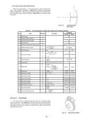
ModulesSAM Angular <strong>Miter</strong> <strong>Gears</strong> 1.5~3∑ =45° B3 Shape ∑ =45°B3 Shape ∑ =60°■ Modules 1.5~3<strong>Miter</strong><strong>Gears</strong>SAMCatalog No. Gear ratio Module No. of teeth Shanft angle ShapeSAM1.5-20045SAM2-20045SAM2.5-20045SAM3-20045SAM1.5-20060SAM2-20060SAM2.5-20060SAM3-20060SAM1.5-20120SAM2-20120SAM2.5-20120SAM3-20120111m1.5m2m2.5m3m1.5m2m2.5m3m1.5m2m2.5m320202020202020202020202045°45°45°45°60°60°60°60°120°120°120°120°B45B45B45B45B60B60B60B60B120B120B120B120Bore Hub dia. Pitch dia. Outside dia. Mounting distance Total length Crown to back lengthAH7 B C D E F GCAUTION: Dimensions of the outside diameter, the overall length and crown to back length are all theoretical values, and some differences will occur due to the cornerchamfering of the gear tips.81012148121416812141625304050253240502634425030405060304050603040506032.7743.6954.6265.5432.5943.4654.3365.1931.54252.56345607590405060702634425019.332<strong>6.</strong>0831.9238.6622.32<strong>6.</strong>3930.4934.5920.692<strong>6.</strong>8633.2239.399.3612.4815.618.7214.771<strong>6.</strong>3617.9419.5418.6424.1829.7335.28∑ =60° ∑ =120°220
Angular <strong>Miter</strong> <strong>Gears</strong>SpecificationsPrecision gradeJIS B 1704 grade 3Tooth hardnessLess than 194HBGear teethGleasonSurface treatmentBlack oxidePressure angleMaterial20°S45CTooth surface finishDatum reference surfacefor gear cuttingCutBoreHeat treatment—Secondary OperationsPossibleB3 Shape Σ=120°Hub width Length of bore Face width Holding surface dia. Allowable torque(N・m) Allowable torque(kgf・m) BacklashH I J K Bending strength Surface durability Bending strength Surface durability7.759.6512.5815.5112.5813.0513.8215.1613.8817.2620.6424.021824303621242832182429351115182291215185<strong>6.</strong>58.5101720.9230.073418.1821.9329.153<strong>6.</strong>3619.222<strong>6.</strong>7832.0339.594.3010.319.634.43.548.391<strong>6.</strong>428.32.435.6611.419.40.380.951.853.300.320.781.562.740.290.701.452.53(mm)NOTE 1: The allowable torques shown in the table are the calculated values according to the assumed usage conditions. Please see page 196 more details.0.441.052.003.510.360.861.672.890.250.581.161.980.0390.0970.190.340.0330.0800.160.280.0300.0720.150.260.05~0.150.06~0.160.07~0.170.08~0.180.05~0.150.06~0.160.07~0.170.08~0.180.05~0.150.06~0.160.07~0.170.08~0.18Weight(kg)0.070.150.310.550.080.150.270.470.070.160.310.53Catalog No.SAM1.5-20045SAM2-20045SAM2.5-20045SAM3-20045SAM1.5-20060SAM2-20060SAM2.5-20060SAM3-20060SAM1.5-20120SAM2-20120SAM2.5-20120SAM3-20120<strong>Miter</strong><strong>Gears</strong>SAM■ Regarding Angular <strong>Miter</strong> <strong>Gears</strong>The shafts of standard miter gears are at 90°. <strong>Miter</strong> gears with other angles are called angular miter gears. SAM series of KHK standard angularmiter gears are available with 45°, 60° and 120° shaft angles. Other shaft angles may be ordered as custom gears. However, because of thelimitations of manufacturing equipment, some gears are not possible to be made.Shaft angle 45° Shaft angle 60° Shaft angle 90° Shaft angle 120°221
SUM Stainless Steel <strong>Miter</strong> <strong>Gears</strong> Modules 1~3■ Modules 1~3B3 Shape<strong>Miter</strong><strong>Gears</strong>SUMCatalog No. Gear ratio Module No. of teeth ShapeSUM1-20SUM1.5-20SUM2-20SUM2.5-20SUM3-20SUM4-20SUM1-25SUM1.5-25SUM2-25SUM2.5-25SUM3-25SUM4-2511m1m1.5m2m2.5m3m4m1m1.5m2m2.5m3m4202020202020252525252525B3B3B3B3B3B3B3B3B3B3B3B3Bore Hub dia. Pitch dia. Outside dia. Mounting distance Total length Crown to back length Hub widthAH7 B C D E F G H681214162061012162028CAUTION: Dimensions of the outside diameter, the overall length and crown to back length are all theoretical values, and some differences will occur due to the cornerchamfering of the gear tips.1626344250642030455565802030405060802537.55062.57510021.4132.1242.8353.5464.2485.652<strong>6.</strong>4139.6252.836<strong>6.</strong>0479.24105.6620303748587523344050608013.9521.2424.8932.5439.8450.7815.1622.2524.3330.4137.8149.3210.711<strong>6.</strong>0618.4124.7730.1237.8311.211<strong>6.</strong>311<strong>6.</strong>4120.5224.6232.8381314192327811.512.51517.520222
Stainless Steel <strong>Miter</strong> <strong>Gears</strong>SpecificationsPrecision gradeJIS B 1704 grade 3Tooth hardnessLess than 187HBGear teethGleasonSurface treatment—Pressure angleMaterialHeat treatment20°SUS303—Tooth surface finishDatum reference surfacefor gear cuttingCutBoreSecondary Operations Possible*Available on special order: Same gear made from SUS304.Length of bore Face width Holding surface dia. Allowable torque(N・m) NOTE 1 Allowable torque(kgf・m) BacklashI J K Bending strength Surface durability Bending strength Surface durability121922293545141920263243581012152069121520259.8615.3721.7228.0631.5743.4315.0319.542<strong>6.</strong>0634.5737.4355.290.491.723.947.5213.331.50.812.74<strong>6.</strong>5012.723.353.20.0600.220.511.001.804.390.120.411.002.003.738.790.0500.180.400.771.363.220.0830.280.661.292.375.430.00610.0220.0520.100.180.450.0120.0420.100.200.380.90(mm)0.03~0.130.05~0.150.06~0.160.07~0.170.08~0.180.12~0.270.03~0.130.05~0.150.06~0.160.07~0.170.08~0.180.12~0.27NOTE1: The allowable torques shown in the table are the calculated values according to the assumed usage conditions. Please see page 196 for more details.Weight(kg)0.020.070.150.300.501.100.030.130.220.410.811.70Catalog No.SUM1-20SUM1.5-20SUM2-20SUM2.5-20SUM3-20SUM4-20SUM1-25SUM1.5-25SUM2-25SUM2.5-25SUM3-25SUM4-25<strong>Miter</strong><strong>Gears</strong>SUM223
PM Plastic <strong>Miter</strong> <strong>Gears</strong> Modules 1~4■ Modules 1~4B3 Shape<strong>Miter</strong><strong>Gears</strong>PMCatalog No. Gear ratio Module No. of teeth ShapePM1-20PM1.25-20PM1.5-20PM2-20PM2.5-20PM3-20PM3.5-20PM4-20PM1-25PM1.25-25PM1.5-25PM2-25PM2.5-2511m1m1.25m1.5m2m2.5m3m3.5m4m1m1.25m1.5m2m2.520202020202020202525252525B3B3B3B3B3B3B3B3B3B3B3B3B3Bore NOTE 1 Hub dia. Pitch dia. Outside dia. Mounting distance Total length Crown to back length Hub widthA B C D E F G H16 20 21.41 20 13.95 10.71 822 25 2<strong>6.</strong>77 23 15.27 11.38 926 30 32.12 30 21.24 1<strong>6.</strong>06 1334 40 42.83 37 24.89 18.41 1442 50 53.54 48 32.54 24.77 1968810121420206881014CAUTION: Dimensions of the outside diameter, the overall length and crown to back length are all theoretical values, and some differences will occur due to the cornerchamfering of the gear tips.NOTE 1: Significant variation in temperature or humidity can cause dimensional changes in plastic gears (MC Nylon gears). Please see the technical section on thecharacteristics of plastic gears (page 32).50606420253040506070802531.2537.55062.564.2474.9585.662<strong>6.</strong>4133.0239.6252.836<strong>6.</strong>04586575232834405039.8444.1350.7815.1617.8822.2524.3330.4130.1232.4737.8311.2113.261<strong>6.</strong>311<strong>6.</strong>4120.52PM3-25 m3 25 B3 15 60 75 79.24 60 37.81 24.62 1523252789.2511.51012.5224
Plastic <strong>Miter</strong> <strong>Gears</strong>SpecificationsPrecision gradeGear teethPressure angleMaterialHeat treatmentJIS B 1704 grade 4Gleason20°MC901—Tooth hardnessSurface treatmentTooth surface finishDatum reference surfacefor gear cutting115~120HRR—CutBoreSecondary Operations PossibleLength of bore Face width Holding surface dia. Allowable torque(N・m) NOTE 2 Allowable torque(kgf・m) Backlash WeightI J K Bending strength Surface durability Bending strength Surface durability (mm) (kg)Catalog No.121319222956810129.8613.0315.3721.7228.060.180.350.611.442.78―――――0.0180.0350.0630.150.28―――――0.08~0.180.09~0.190.10~0.200.11~0.210.12~0.220.010.010.010.020.04PM1-20PM1.25-20PM1.5-20PM2-20PM2.5-2035404515182031.5739.0943.434.857.7511.5―――0.490.791.17―――0.13~0.230.15~0.250.17~0.270.070.120.16PM3-20PM3.5-20PM4-201416192026679121515.0318.719.542<strong>6.</strong>0634.570.300.561.002.364.61―――――0.0300.0580.100.240.47―――――0.08~0.180.09~0.190.10~0.200.11~0.210.12~0.220.010.010.020.030.06PM1-25PM1.25-25PM1.5-25PM2-25PM2.5-2532 20 37.43 8.15 ― 0.83 ― 0.13~0.23 0.10 PM3-25NOTE 2: The allowable torques shown in the table are the calculated values using the Lewis formula.<strong>Miter</strong><strong>Gears</strong>PM225
DM Injection Molded <strong>Miter</strong> <strong>Gears</strong> Modules■ Modules 0.5~1.5B1 Shape■ Dimensional tolerance table (unit: mm)Range30 mm up0.5~1.5ToleranceBelow 3mm ±0.203 up to 6 mm ±0.256 up to 10 mm ±0.3010 up to 18 mm ±0.3518 up to 30 mm ±0.40±0.50Precision gradeGear teethPressure angleMaterialHeat treatmentTooth hardnessSurface treatmentSpecificationsJIS B 1704 grade 8Gleason20°Duracon(M90-44)—110~120HRR—Tooth surface finish Injection moldedDatum reference surfacefor tooth forming BoreSecondary Operations Not recommended<strong>Miter</strong><strong>Gears</strong>DṂBBCatalog No. Gear ratio Module No. of teeth ShapeDM0.5-20DM0.8-20DM1-20DM1.5-201m0.5m0.8m1m1.520202020B1B1B1B1Bore NOTE 1 Hub dia. Pitch dia. Outside dia. Mounting distance Total length Crown to back lengthA B C D E F G3 8 10 10.71 11 7.97 <strong>6.</strong>355 12 16 17.13 16 10.83 8.566 16 20 21.41 21 14.62 11.718 20 30 32.12 30 20.59 1<strong>6.</strong>06NOTE 1: The bore tolerance is generally –0.05 to –0.1 but may be + value at the central portion of the hole. Re-machining the bore is not recommended since reworkingmaterial may expose voids.Hub width Length of bore Face width Holding surface dia. Allowable torque(N・m) NOTE 2 Allowable torque(kgf・m) BacklashH I J K Bending strength Bending strength4571071013192.53.54.574.9310.111.2718.20.0820.310.540.960.00830.0320.0550.098(mm)0.04~0.140.06~0.160.08~0.180.10~0.20Weight(kg)12413Catalog No.DM0.5-20DM0.8-20DM1-20DM1.5-20NOTE 2: The allowable torques shown in the table are the calculated values using the Lewis formula.BB Sintered Metal BushingsThe table shows a series of standard metal bushings that can bepressed into standard injection molded gears. They can be usedas bearing metal on idler gears or to reduce the bore of the gears.CatalogNo.I.D. of bushingd +0.020O.D. of bushingBB30507 3 5 07 DS0.5, DM0.8, DB0.8BB30608 3 6 08 DS0.5, DS0.8, DM1BB40609 4 6 09 DS0.8, DM1BB40612 4 6 12 DS1, DB1BB50812 5 8 12 DS1BB50814 5 8 14 DS1, DM1.5Material: Oil impregnated sintered bronze.LengthD +0.02-0.01 L 0-0.3(unit: mm)Products that can use the bushing226