GPR-1100 Portable ppm Oxygen Analyzer - Advanced Instruments Inc.
GPR-1100 Portable ppm Oxygen Analyzer - Advanced Instruments Inc.
GPR-1100 Portable ppm Oxygen Analyzer - Advanced Instruments Inc.

Create successful ePaper yourself
Turn your PDF publications into a flip-book with our unique Google optimized e-Paper software.
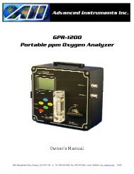
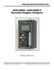
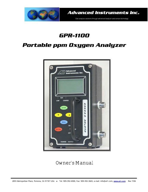
<strong>GPR</strong>-<strong>1100</strong><br />
<strong>Portable</strong> <strong>ppm</strong> <strong>Oxygen</strong> <strong>Analyzer</strong><br />
Owner’s Manual<br />
2855 Metropolitan Place, Pomona, CA 91767 USA ♦ Tel: 909-392-6900, Fax: 909-392-3665, e-mail: info@aii1.com, www.aii1.com Rev 7/06
Table of Contents<br />
Introduction<br />
1<br />
Quality Control Certification<br />
2<br />
Safety<br />
3<br />
Features & Specifications<br />
4<br />
Operation<br />
5<br />
Maintenance<br />
6<br />
Spare Parts<br />
7<br />
Troubleshooting<br />
8<br />
Warranty<br />
9<br />
Material Safety Data Sheets<br />
10<br />
Drawings<br />
A/R<br />
2
1 Introduction<br />
Your new portable oxygen analyzer incorporates an advanced electrochemical sensor specific to oxygen along with<br />
state-of-the-art digital electronics designed to give you years of reliable precise oxygen measurements in variety of<br />
industrial oxygen applications.<br />
To obtain maximum performance from your new oxygen analyzer, please read and follow the guidelines provided<br />
in this Owner’s Manual.<br />
Every effort has been made to select the most reliable state of the art materials and components; and, to design<br />
the analyzer for superior performance and minimal cost of ownership. This analyzer was tested thoroughly by the<br />
manufacturer prior to shipment for best performance.<br />
However, modern electronic devices do require service from time to time. The warranty included herein plus a staff<br />
of trained professional technicians to quickly service your analyzer is your assurance that we stand behind every<br />
analyzer sold.<br />
The serial number of this analyzer may be found on the inside the analyzer. You should note the serial number in<br />
the space provided and retains this Owner’s Manual as a permanent record of your purchase, for future reference<br />
and for warranty considerations.<br />
Serial Number: _______________________<br />
<strong>Advanced</strong> <strong>Instruments</strong> <strong>Inc</strong>. appreciates your business and pledges to make every effort to maintain the highest<br />
possible quality standards with respect to product design, manufacturing and service.<br />
3
2 Quality Control Certification<br />
Date: Customer: Order No.: Pass<br />
Model<br />
<strong>GPR</strong>-<strong>1100</strong> <strong>Portable</strong> <strong>ppm</strong> <strong>Oxygen</strong> <strong>Analyzer</strong><br />
Sensor ( ) <strong>GPR</strong>-12-333 <strong>ppm</strong> <strong>Oxygen</strong> Sensor<br />
( ) XLT-12-333 <strong>ppm</strong> <strong>Oxygen</strong> Sensor<br />
Serial Nos.<br />
Accessories<br />
<strong>Analyzer</strong>_________________________ Sensor _____________________________<br />
Owner’s Manual<br />
( ) PWRS-1002 9VDC Battery Charger/Adapter 110VAC<br />
( ) PWRS-1003 9VDC Battery Charger/Adapter 220VAC<br />
( ) PWRS-1008 9VDC Battery Charger/Adapter 12VDC Auto Cigarette Lighter<br />
CONN-1034 Plug Mini Phone .141 dia. Black Handle<br />
FITN-1003 (3x) Plug Male Quick Disconnect Fittings<br />
TOOL-1001 5/16 Combination Wrench<br />
Configuration<br />
A-1151-E-B1 PCB Assembly<br />
Range: 0-10 <strong>ppm</strong>, 0-100 <strong>ppm</strong>, 0-1000 <strong>ppm</strong>, 0-25%<br />
Wetted parts: stainless steel<br />
Electronics Test<br />
LED indicators: Low battery, charge<br />
Electronic offset<br />
Analog signal output 0-1V<br />
Gas Phase Test<br />
Recovery from air to < 10 <strong>ppm</strong> in < 1 hour<br />
Baseline drift on zero gas < ± 2% FS over 24 hour period on 0-1% range<br />
Noise level < ± 0.5% FS<br />
Span adjustment within 10-50% FS<br />
Final<br />
Overall inspection for physical defects<br />
Options<br />
Notes<br />
4
3 Safety<br />
General<br />
This section summarizes the essential precautions applicable to the <strong>GPR</strong>-<strong>1100</strong> Series <strong>Portable</strong> <strong>ppm</strong> <strong>Oxygen</strong><br />
<strong>Analyzer</strong>. Additional precautions specific to individual analyzer are contained in the following sections of this<br />
manual. To operate the analyzer safely and obtain maximum performance follow the basic guidelines outlined in<br />
this Owner’s Manual.<br />
Caution: This symbol is used throughout the Owner’s Manual to CAUTION and alert the user to recommended<br />
safety and/or operating guidelines.<br />
Danger: This symbol is used throughout the Owner’s Manual to identify sources of immediate DANGER such as<br />
the presence of hazardous voltages.<br />
Read Instructions: Before operating the analyzer read the instructions.<br />
Retain Instructions: The safety precautions and operating instructions found in the Owner’s Manual should be<br />
retained for future reference.<br />
Heed Warnings: Follow all warnings on the analyzer, accessories (if any) and in this Owner’s Manual.<br />
Follow Instructions: Observe all precautions and operating instructions. Failure to do so may result in personal<br />
injury or damage to the analyzer.<br />
Installation<br />
<strong>Oxygen</strong> Sensor: DO NOT open the sensor. The sensor contains a corrosive liquid electrolyte that could be<br />
harmful if touched or ingested, refer to the Material Safety Data Sheet contained in the Owner’s Manual appendix.<br />
Avoid contact with any liquid or crystal type powder in or around the sensor or sensor housing, as either could be a<br />
form of electrolyte. Leaking sensors should be disposed of in accordance with local regulations.<br />
Inlet Pressure: The analyzer is designed for flowing samples are intended to operate at positive pressure<br />
regulated to between 5-30 psig.<br />
Outlet Pressure: The sample gas vent pressure should be atmospheric.<br />
Flow Rate: Recommended – 2 SCFH or 1 liter per minute.<br />
Mounting: Mount as recommended by the manufacturer. The analyzer is approved for indoor or outdoor use.<br />
Power: Supply power to the analyzer only as rated by the specification or markings on the analyzer enclosure. The<br />
wiring that connects the analyzer to the power source should be installed in accordance with recognized electrical<br />
standards and so they are not pinched particularly near the power source and the point where they attach to the<br />
analyzer. Never yank wiring to remove it from an outlet or from the analyzer.<br />
Operating Temperature: The maximum operating temperature is 45º C.<br />
Heat: Situate and store the analyzer away from sources of heat.<br />
Liquid and Object Entry: The analyzer should not be immersed in any liquid. Care should be taken so that<br />
liquids are not spilled into and objects do not fall into the inside of the analyzer.<br />
Handling: Do not use force when using the switches and knobs. Before moving your analyzer be sure to<br />
disconnect the wiring/power cord and any cables connected to the output terminals located on the analyzer.<br />
5
Maintenance<br />
Serviceability: Except for replacing the oxygen sensor, there are no parts inside the analyzer for the operator to<br />
service.<br />
Only trained personnel with the authorization of their supervisor should conduct maintenance.<br />
<strong>Oxygen</strong> Sensor: DO NOT open the sensor. The sensor contains a corrosive liquid electrolyte that could be<br />
harmful if touched or ingested, refer to the Material Safety Data Sheet contained in the Owner’s Manual appendix.<br />
Avoid contact with any liquid or crystal type powder in or around the sensor or sensor housing, as either could be a<br />
form of electrolyte. Leaking sensors should be disposed of in accordance with local regulations.<br />
Troubleshooting: Consult the guidelines in Section 8 for advice on the common operating errors before<br />
concluding that your analyzer is faulty.<br />
Do not attempt to service the analyzer beyond those means described in this Owner’s Manual. Do not attempt to<br />
make repairs by yourself as this will void the warranty as per Section 10 and may result in electrical shock, injury or<br />
damage. All other servicing should be referred to qualified service personnel.<br />
Cleaning: The analyzer should be cleaned only as recommended by the manufacturer. Wipe off dust and dirt from<br />
the outside of the unit with a soft damp cloth then dry immediately. Do not use solvents or chemicals.<br />
Nonuse Periods: If the analyzer is equipped with a range switch advance the switch to the OFF position and<br />
disconnect the power when the analyzer is left unused for a long period of time.<br />
4 Features & Specifications<br />
See last page, this page left blank intentionally.<br />
6
5 Operation<br />
Principle of Operation<br />
The <strong>GPR</strong>-<strong>1100</strong> portable oxygen analyzer incorporates a variety of <strong>ppm</strong> range advanced galvanic fuel cell type<br />
sensors. The analyzer is configured in a general purpose NEMA 4 rated enclosure and meets the intrinsic safety<br />
standards required for use in Class 1, Division 1, Groups A, B, C, D hazardous areas. Two integral sampling pump<br />
options are available – one that meets the intrinsic safety standards and a less expensive option for general<br />
purpose service.<br />
<strong>Advanced</strong> Galvanic Sensor Technology:<br />
The sensors function on the same principle and are specific for oxygen. They measure the partial pressure of<br />
oxygen from low <strong>ppm</strong> to 100% levels in inert gases, gaseous hydrocarbons, helium, hydrogen, mixed gases, acid<br />
gas streams and ambient air. <strong>Oxygen</strong>, the fuel for this electrochemical transducer, diffusing into the sensor reacts<br />
chemically at the sensing electrode to produce an electrical current output proportional to the oxygen concentration<br />
in the gas phase. The sensor’s signal output is linear over all ranges and remains virtually constant over its useful<br />
life. The sensor requires no maintenance and is easily and safely replaced at the end of its useful life.<br />
Proprietary advancements in design and chemistry add significant advantages to an extremely versatile oxygen<br />
sensing technology. Sensors for low <strong>ppm</strong> analysis recover from air to <strong>ppm</strong> levels in minutes, exhibit longer life and<br />
reliable quality. The expected life of our new generation of percentage range sensors now range to five and ten<br />
years with faster response times and greater stability. Another significant development involves expanding the<br />
operating temperature range for percentage range sensors from -30°C to 50°C.<br />
Electronics:<br />
The signal generated by the sensor is processed by state of the art low power micro-processor based digital<br />
circuitry. The first stage amplifies the signal. The second stage eliminates the low frequency noise. The third stage<br />
employs a high frequency filter and compensates for signal output variations caused by ambient temperature<br />
changes. The result is a very stable signal. Sample oxygen is analyzed very accurately. Response time of 90% of<br />
full scale is less than 10 seconds (actual experience may vary due to the integrity of sample line connections, dead<br />
volume and flow rate selected) on all ranges under ambient monitoring conditions. Sensitivity is typically 0.5% of<br />
full scale low range. <strong>Oxygen</strong> readings may be recorded by an external device via the 0-1V signal output jack.<br />
Power is supplied by an integral rechargeable lead acid battery which provides enough power to operate the<br />
analyzer continuously for approximately 60 days. An LED located on the front panel provides a blinking 72 hour<br />
warning to recharge the battery. A 9VAC adapter (positive pole located on the inside of the female connector) can<br />
be used to recharge the battery from a convenience outlet. The analyzer is designed to be fully operational during<br />
the 8-10 hour charging cycle which is indicated by a second continuously lit LED.<br />
Sample System:<br />
The <strong>GPR</strong>-<strong>1100</strong> is supplied without a sample conditioning system for maximum portability. However the sample<br />
must be properly presented to the sensor to ensure an accurate measurement. Users interested in adding their<br />
own sample conditioning system should consult the factory. <strong>Advanced</strong> <strong>Instruments</strong> <strong>Inc</strong>. offers a full line of sample<br />
handling, conditioning and expertise to meet your application requirements. Contact us at 909-392-6900 or e-mail<br />
us at aii2@earthlink.net<br />
7
Pressure & Flow<br />
All electrochemical oxygen sensors respond to partial pressure changes in oxygen. The inlet pressure must always<br />
be higher than the pressure at the outlet vent which is normally at atmospheric pressure.<br />
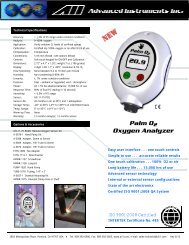
Flow Through Configuration:<br />
The sensor is exposed to sample gas that must flow or be drawn<br />
through metal tubing inside the analyzer. The <strong>GPR</strong>-<strong>1100</strong> internal<br />
sample system includes a quick disconnect female inlet fitting, a<br />
stainless steel sensor housing with an o-ring seal to prevent the<br />
leakage of air and another quick disconnect female vent fitting.<br />
Mating male quick disconnect fittings are provided for introducing<br />
sample and calibration gases, a third male fitting is provided for the<br />
vent line.<br />
Flow rates of 1-5 SCFH cause no appreciable change in the oxygen<br />
reading. However, flow rates above 5 SCFH generate backpressure<br />
and erroneous oxygen readings because the diameter of the<br />
integral tubing cannot evacuate the sample gas at the higher flow<br />
rate. The direction the sample gas flows is not important, thus<br />
either female fitting can serve as the inlet or vent – just not<br />
simultaneously.<br />
A flow indicator with an integral metering valve upstream of the<br />
sensor is recommended as a means of controlling the flow rate of<br />
the sample gas. A flow rate of 2 SCFH or 1liter per minute is<br />
recommended for optimum performance.<br />
Caution: Do not place your finger over the vent (it pressurizes the sensor) to test the flow indicator when gas is<br />
flowing to the sensor. Removing your finger (the restriction) generates a vacuum on the sensor and may damage<br />
the sensor (voiding the sensor warranty).<br />
To avoid generating a vacuum on the sensor (as described above) during operation, always<br />
select and install the vent fitting first and remove the vent fitting last.<br />
Application Pressure - Positive:<br />
A flow indicator with integral metering valve (<strong>GPR</strong>-<strong>1100</strong>M option) positioned upstream of the<br />
sensor is recommended for controlling the sample flow rate between 1-5 SCFH.<br />
If necessary, a pressure regulator (with a metallic diaphragm is recommended for optimum<br />
accuracy, the use of diaphragms of more permeable materials may result in erroneous<br />
readings) upstream of the flow control valve should be used to regulate the inlet pressure<br />
between 5-30 psig.<br />
8
Application Pressure - Atmospheric or Slightly Negative:<br />
For accurate <strong>ppm</strong> range oxygen measurements, an optional external sampling pump should be positioned<br />
downstream of the sensor to draw the sample from the process, by the sensor and out to atmosphere. A flow<br />
meter is generally not necessary to obtain the recommended flow rate with most sampling pumps, if the analyzer is<br />
equipped with a flow meter make sure the valve is completely open to avoid drawing a vacuum on the sensor.<br />
Caution: If the analyzer is equipped with an optional flow indicator with integral metering valve (<strong>GPR</strong>-<strong>1100</strong>M)<br />
upstream of the sensor - open the metering valve completely to avoid drawing a vacuum on the sensor and placing<br />
an undue burden on the pump.<br />
If pump loading is a consideration, a second throttle valve on the pump’s inlet side may be necessary to provide a<br />
bypass path so the sample flow rate is within the above parameters.<br />
To avoid erroneous oxygen readings and damaging the sensor:<br />
‣ Do not place your finger over the vent (it pressurizes the sensor) to test the flow indicator when gas is flowing<br />
to the sensor. Removing your finger (the restriction) generates a vacuum on the sensor and may damage the<br />
sensor (voiding the sensor warranty).<br />
‣ Assure there are no restrictions in the sample or vent lines<br />
‣ Avoid drawing a vacuum that exceeds 14” of water column pressure – unless done gradually<br />
‣ Avoid excessive flow rates above 5 SCFH which generate backpressure on the sensor.<br />
‣ Avoid sudden releases of backpressure that can severely damage the sensor.<br />
‣ Avoid the collection of particulates, liquids or condensation collect on the sensor that could block the diffusion<br />
of oxygen into the sensor.<br />
9
Calibration & Accuracy<br />
Single Point Calibration: As previously described the galvanic oxygen sensor generates an electrical current<br />
sensor exhibiting an absolute zero, e.g. the sensor does not generate a current output in the absence of oxygen.<br />
Given these linearity and absolute zero properties, single point calibration is possible.<br />
Pressure: Because sensors are sensitive to the partial pressure of oxygen in the sample gas their output is a<br />
function of the number of molecules of oxygen 'per unit volume'. Readouts in percent are permissible only when<br />
the total pressure of the sample gas being analyzed remains constant. The pressure of the sample gas and that of<br />
the calibration gas(es) must be the same (reality < 1-2 psi).<br />
Temperature: The rate oxygen molecules diffuse into the sensor is controlled by a Teflon membrane otherwise<br />
known as an 'oxygen diffusion limiting barrier' and all diffusion processes are temperature sensitive, the fact the<br />
sensor's electrical output will vary with temperature is normal. This variation is relatively constant 2.5% per ºC. A<br />
temperature compensation circuit employing a thermistor offsets this effect with an accuracy of +5% or better and<br />
generates an output function that is independent of temperature. There is no error if the calibration and sampling<br />
are performed at the same temperature or if the measurement is made immediately after calibration. Lastly, small<br />
temperature variations of 10-15º produce < +1% error.<br />
Accuracy: In light of the above parameters, the overall accuracy of an analyzer is affected by two types of<br />
errors: 1) those producing 'percent of reading errors', illustrated by Graph A below, such as +5% temperature<br />
compensation circuit, tolerances of range resistors and the 'play' in the potentiometer used to make span<br />
adjustments and 2) those producing 'percent of full scale errors', illustrated by Graph B, such as +1-2% linearity<br />
errors in readout devices, which are really minimal due to today's technology and the fact that other errors are<br />
'spanned out' during calibration.<br />
Graph C illustrates these 'worse case' specifications that are typically used to develop an analyzer's overall accuracy<br />
statement of +2% of full scale at constant temperature or +5% over the operating temperature range. QC testing<br />
is typically
Example: As illustrated by Graph A any error, play in the multi-turn span pot or the temperature compensation<br />
circuit, during a span adjustment at 20.9% (air) of full scale range would be multiplied by a factor of 4.78<br />
(100/20.9) if used for measurements of 95-100% oxygen concentrations. Conversely, an error during a span<br />
adjustment at 100% of full scale range is reduced proportionately for measurements of lower oxygen<br />
concentrations.<br />
Recommendation: Calibrating with a span gas approximating 80% of the full scale range one or two ranges<br />
higher than the full scale range of interest is recommended for 'optimum calibration accuracy'.<br />
11
Start-up<br />
The <strong>GPR</strong>-<strong>1100</strong> <strong>Portable</strong> <strong>ppm</strong> <strong>Oxygen</strong> <strong>Analyzer</strong> is fully operational from the shipping container with the oxygen<br />
sensor installed and calibrated at the factory prior to shipment. Once installed, we recommend the user allow the<br />
analyzer to stabilize for 30 minutes and then recalibrate the device as instructed below.<br />
Assemble the necessary hardware for mounting the analyzer and optional components - such as coalescing or<br />
particulate filters and pumps, 1/8” metal or plastic tubing for interconnecting the analyzer and optional<br />
components.<br />
Review the application conditions to ensure the sample is suitable for analysis.<br />
1. Temperature: The sample must be sufficiently cooled before it enters the analyzer and any optional<br />
components. A coiled 10 foot length of ¼” stainless steel tubing is sufficient for cooling sample gases as high<br />
as 1,800ºF to ambient.<br />
2. Pressure & Flow: As described above.<br />
3. Moisture & Particulates: Prevent water and/or particulates from entering the sample system. They can clog<br />
the tubing and damage the optional components such as pumps, scrubbers or sensors. Installation of a<br />
suitable coalescing or particulate filter is required to remove condensation, moisture and/or particulates from<br />
the sample gas to prevent erroneous analysis readings and damage to the sensor or optional components.<br />
Consult the factory for recommendations concerning the proper selection and installation of components.<br />
4. Contaminants: A gas scrubber and flow indicator with integral metering valve are required upstream of the<br />
analyzer to remove interfering gases such as oxides of sulfur and nitrogen or hydrogen sulfide that can<br />
produce false readings and reduce the expected life of the sensor. Installation of a suitable scrubber is required<br />
to remove the contaminant from the sample gas to prevent erroneous analysis readings and damage to the<br />
sensor or optional components. Consult the factory for recommendations concerning the proper selection and<br />
installation of components.<br />
5. Gas connections: Inlet and outlet vent gas lines require 1/8” diameter tubing preferably metal.<br />
6. Power connection: Locate a source of AC power to meet area classification and to plug in the charging adapter.<br />
7. Zero calibration (required only for very low percentage range measurements).<br />
8. Span calibration – Users are responsible for certified span gas cylinder, regulator and flow control valve.<br />
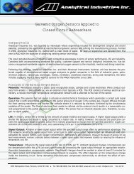
Mounting the <strong>Analyzer</strong>:<br />
Normally mounting a portable analyzer is not a consideration. However, the <strong>GPR</strong>-<strong>1100</strong> analyzer can operate<br />
continuously when connected to AC power using the appropriate charging adapter. The analyzer enclosure is cast<br />
with four (4) holes in the bottom section specifically intended for wall mounting.<br />
12
Gas Connections:<br />
The <strong>GPR</strong>-<strong>1100</strong> flow through configuration is designed for positive<br />
pressure samples and requires connections to incoming sample and<br />
vent female quick disconnect fittings. The user is responsible for<br />
making provision for introducing gases for calibration purposes.<br />
Flow rates of 1-5 SCFH cause no appreciable change in the oxygen<br />
reading. However, flow rates above 5 SCFH generate backpressure<br />
and erroneous oxygen readings because the diameter of the integral<br />
tubing cannot evacuate the sample gas at the higher flow rate.<br />
A flow indicator with an integral metering valve upstream of the sensor<br />
is recommended as a means of controlling the flow rate of the sample<br />
gas. A flow rate of 2 SCFH or 1 liter per minute is recommended for<br />
optimum performance.<br />
Caution: Do not place your finger over the vent (it pressurizes the<br />
sensor) to test the flow indicator when gas is flowing to the sensor.<br />
Removing your finger (the restriction) generates a vacuum on the<br />
sensor and may damage the sensor (voiding the sensor warranty).<br />
To avoid generating a vacuum on the sensor (as described above)<br />
during operation, always select and install the vent fitting first and<br />
remove the vent fitting last.<br />
Procedure:<br />
1. Caution: Do not change the factory setting until instructed.<br />
2. Designate the female quick disconnect fittings, right side of the analyzer, as inlet and vent respectively.<br />
3. Regulate the pressure and flow as described in Pressure & Flow above.<br />
4. Install one mating male vent fitting into the female quick disconnect fitting designated as the VENT –<br />
connection of 1/8” dia. metal vent line (requires an 1/8” male NPT to tube adapter) is optional.<br />
5. Connect the second mating male fitting to 1/8” dia. metal sample line using a 1/8” male NPT to tube adapter.<br />
6. Connect the third mating male fitting to 1/8” dia. metal span gas line using a 1/8” male NPT to tube adapter.<br />
7. Install either the sample or span mating male fitting into the female quick disconnect fitting designated as<br />
SAMPLE.<br />
8. Set the flow rate to 2 SCFH (open the flow control valve completely if using an external sampling pump<br />
positioned downstream of the sensor).<br />
9. Allow gas to flow through the analyzer for 3-5 minutes and proceed to Calibration or Sampling.<br />
13
Power connection:<br />
Locate a source of AC power to meet the area classification, plug in the appropriate charging adapter to the outlet<br />
and connect the jack at the other end to the mating receptacle identified on the analyzer.<br />
Output connection:<br />
The analyzer provides a 0-1V full scale with negative ground signal output for external recording devices.<br />
Procedure:<br />
Connect the lead wires from the external recording device to the male phone plug supplied with analyzer. (Note:<br />
Connect the positive lead to the center terminal of the male phone plug.)<br />
Insert the male phone plug into the integral female OUTPUT jack located on the side of the enclosure.<br />
Installing the <strong>Oxygen</strong> Sensor<br />
<strong>GPR</strong>-<strong>1100</strong> <strong>Portable</strong> <strong>ppm</strong> <strong>Oxygen</strong> <strong>Analyzer</strong> is equipped with an integral oxygen sensor. They are fully operational<br />
from the shipping container with the oxygen sensor installed, tested and calibrated by the manufacturer prior to<br />
shipment. Should it be necessary to install the oxygen sensor – see section 6 Maintenance which covers replacing<br />
the oxygen sensor.<br />
Caution: All analyzer must be calibrated once the installation has been completed and periodically thereafter as<br />
described below.<br />
Caution: DO NOT open the oxygen sensor. The sensor contains a corrosive liquid electrolyte that could be harmful<br />
if touched or ingested, refer to the Material Safety Data Sheet in section 10. Avoid contact with any liquid or crystal<br />
type powder in or around the sensor or sensor housing, as either could be a form of electrolyte. Leaking sensors<br />
should be disposed of in accordance with local regulations.<br />
Span Gas Preparation<br />
Caution: Do not contaminate the span gas cylinder when connecting the regulator. Bleed the air filled regulator<br />
(faster and more reliable than simply flowing the span gas) before attempting the initial calibration of the<br />
instrument.<br />
1. With the span gas cylinder valve closed, install the regulator on the cylinder.<br />
2. Open the regulator’s exit valve and partially open the pressure regulator’s control knob.<br />
3. Open slightly the cylinder valve.<br />
4. Loosen the nut connecting the regulator to the cylinder and bleed the pressure regulator.<br />
5. Retighten the nut connecting the regulator to the cylinder<br />
6. Adjust the regulator exit valve and slowly bleed the pressure regulator.<br />
7. Open the cylinder valve completely.<br />
8. Set the pressure between 5-30 psig using the pressure regulator’s control knob.<br />
Caution: Do not exceed the recommended flow rate. Excessive flow rate could cause the backpressure on the<br />
sensor and may result in erroneous readings and permanent damage to the sensor.<br />
14
Establishing Power to the Electronics:<br />
Establish power to the analyzer electronics by pushing the red ON/OFF key. The digital display responds<br />
instantaneously. When power is applied, the analyzer performs several diagnostic system status checks termed<br />
“START-UP TEST” as illustrated below:<br />
START-UP TEST<br />
ELECTRONICS – PASS<br />
BATTERY – PASS<br />
TEMP SENSOR – PASS<br />
BARO – N/A<br />
REV. 1.37<br />
In the unlikely event the LED warning indicator LOW BATT comes<br />
on when the analyzer is turned on – proceed immediately to the<br />
sub-section on Battery Considerations at the end of section 5<br />
Operation.<br />
Note: The analyzer display defaults to the sampling mode when<br />
30 seconds elapses without user interface.<br />
00.00 PPM<br />
AUTO SAMPLING<br />
10 PPM RANGE<br />
24.5 C<br />
Menu Navigation:<br />
The five (5) pushbuttons located on the front of the analyzer<br />
operate the micro-processor:<br />
1. green ENTER (select)<br />
2. yellow UP ARROW<br />
3. yellow DOWN ARROW<br />
4. blue MENU (escape)<br />
5. red ON/OFF<br />
15
Main Menu:<br />
Access the MAIN MENU by pressing the MENU key:<br />
MAIN MENU<br />
AUTO SAMPLE<br />
MANUAL SAMPLE<br />
SPAN CALIBRATE<br />
ZERO CALIBRATE<br />
DEFAULT SPAN<br />
DEFAULT ZERO<br />
Range Selection:<br />
The <strong>GPR</strong>-<strong>1100</strong> analyzer is equipped with five (5) standard measuring ranges (see specification) and provides users<br />
with a choice of sampling modes. By accessing the MAIN MENU, users may select either the AUTO SAMPLING<br />
(ranging) or MANUAL SAMPLING (to lock on a single range) mode.<br />
Note: For calibration purposes, use of the AUTO SAMPLE mode is recommended. However, the user can select the<br />
full scale MANUAL SAMPLE RANGE for calibration as dictated by the accuracy of the analysis required – for<br />
example, a span gas with an 80 <strong>ppm</strong> oxygen concentration with the balance nitrogen would dictate the use of the<br />
0-100 <strong>ppm</strong> full scale range for calibration and a 0-10 <strong>ppm</strong> measuring range.<br />
Procedure - Auto Sampling:<br />
1. Access the MAIN MENU by pressing the MENU key.<br />
2. Advance the reverse shade cursor to highlight AUTO SAMPLE.<br />
3. Press the ENTER key to select the highlighted menu option.<br />
4. The display returns to the sampling mode:<br />
MAIN MENU<br />
00.00 PPM<br />
AUTO SAMPLE<br />
MANUAL SAMPLE<br />
SPAN CALIBRATE<br />
ZERO CALIBRATE<br />
DEFAULT SPAN<br />
DEFAULT ZERO<br />
>>><br />
24.5 C<br />
AUTO SAMPLING<br />
10 PPM RANGE<br />
The display will shift to the next higher range when the oxygen reading (actually the sensor’s signal output)<br />
exceeds 99.9% of the upper limit of the current range. The display will shift to the next lower range when the<br />
oxygen reading drops to 85% of the upper limit of the next lower range.<br />
16
For example, if the analyzer is reading 1% on the 0-10% range and an upset occurs, the display will shift to the 0-<br />
25% range when the oxygen reading exceeds 9.9%. Conversely, once the upset condition is corrected, the display<br />
will shift back to the 0-10% range when the oxygen reading drops to 8.5%.<br />
Procedure - Manual Sampling:<br />
1. Access the MAIN MENU by pressing the MENU key.<br />
2. Advance the reverse shade cursor to highlight MANUAL SAMPLE.<br />
3. Press the ENTER key to select the highlighted menu option.<br />
4. The following displays appears:<br />
MAIN MENU<br />
AUTO SAMPLE<br />
MANUAL SAMPLE<br />
SPAN CALIBRATE<br />
ZERO CALIBRATE<br />
DEFAULT SPAN<br />
DEFAULT ZERO<br />
>>><br />
25%<br />
1%<br />
1000 PPM<br />
100 PPM<br />
10 PPM<br />
MANUAL RANGE<br />
5. Advance the reverse shade cursor to highlight the desired RANGE.<br />
6. Press the ENTER key to select the highlighted menu option.<br />
7. The following display(s) appear depending on the range selected and oxygen concentration of the sample gas:<br />
00.00 PPM<br />
00.00 PPM<br />
MANUAL SAMPLING<br />
10 PPM RANGE<br />
OR<br />
OVERRANGE<br />
AUTO SAMPLING<br />
10 PPM RANGE<br />
24.5 C<br />
24.5 C<br />
000.0 PPM<br />
000.0 PPM<br />
MANUAL SAMPLING<br />
100 PPM RANGE<br />
OR<br />
OVERRANGE<br />
AUTO SAMPLING<br />
100 PPM RANGE<br />
24.5 C<br />
24.5 C<br />
17
0.000 PPM<br />
0.000 PPM<br />
MANUAL SAMPLING<br />
1000 PPM RANGE<br />
OR<br />
OVERRANGE<br />
AUTO SAMPLING<br />
1000 PPM RANGE<br />
24.5 C<br />
24.5 C<br />
0.000 %<br />
0.000 %<br />
MANUAL SAMPLING<br />
1% RANGE<br />
OR<br />
OVERRANGE<br />
AUTO SAMPLING<br />
1% RANGE<br />
24.5 C<br />
24.5 C<br />
00.00 %<br />
00.00 %<br />
MANUAL SAMPLING<br />
25% RANGE<br />
OR<br />
OVERRANGE<br />
AUTO SAMPLING<br />
25% RANGE<br />
24.5 C<br />
24.5 C<br />
The display will not shift automatically. Instead, when the oxygen reading (actually the sensor’s signal output)<br />
exceeds 110% of the upper limit of the current range an OVER RANGE warning will be displayed.<br />
Once the OVER RANGE warning appears the user must advance the analyzer to the next higher range via the menu<br />
and keypad Press MENU, select MANUAL SAMPLING, press ENTER, select the appropriate MANUAL RANGE and<br />
press ENTER again.<br />
Start-Up is complete . . . proceed to Calibration<br />
18
Zero Calibration<br />
In theory, the oxygen sensor produces no signal output when exposed to an oxygen free sample gas. However, the<br />
analyzer will generate an oxygen reading when sampling oxygen free sample gas due to:<br />
‣ Contamination or quality of the zero gas<br />
‣ Minor leakage in the sample line connections<br />
‣ Residual oxygen dissolved in the sensor’s electrolyte<br />
‣ Tolerances of the electronic components<br />
Recommendation: Zero calibration is recommended for measurements below 1 <strong>ppm</strong> on the 10 <strong>ppm</strong> range only,<br />
as it is not practical on higher ranges as described below.<br />
Procedure:<br />
Zero calibration should precede the span calibration and once performed should not have to be repeated with<br />
subsequent span calibrations. Normally, zero calibrations are performed when a new sensor is installed or changes<br />
are made in the sample system connections.<br />
Refer to Span Calibration below for the detailed procedure. Differences include substituting a suitable zero gas for<br />
the span gas and allowing the analyzer 24 hours with flowing zero gas to determine the true zero offset (a stable<br />
reading evidenced by a horizontal trend on an external recording device) of the system before conducting the zero<br />
calibration. Note: 24 hours is required for the sensor to consume the oxygen that has dissolved into the electrolyte<br />
inside the sensor (while exposed to air or percentage levels of oxygen).<br />
Thus, for this reasons above, it is not practical to zero a portable analyzer every time it is moved from one sample<br />
point to another. Finding the true zero offset is not always necessary particularly in the case of applications<br />
requiring higher level oxygen measurements because of the low offset value, normally < 0.1 <strong>ppm</strong>, is not material<br />
to the accuracy of higher level measurements.<br />
Note: Prematurely zeroing the analyzer can cause a negative reading in both the ZERO and SAMPLE modes.<br />
1. Access the MAIN MENU by pressing the MENU key.<br />
2. Advance the reverse shade cursor to highlight ZERO CALIBRATE.<br />
3. Press the ENTER key to select the highlighted menu option.<br />
4. The following displays appear:<br />
MAIN MENU<br />
AUTO SAMPLE<br />
MANUAL SAMPLE<br />
SPAN CALIBRATE<br />
ZERO CALIBRATE<br />
DEFAULT SPAN<br />
DEFAULT ZERO<br />
>>><br />
0.000 PPM<br />
ZERO<br />
CALIBRTION<br />
ENTER TO CALIBRATE<br />
ESCAPE TO ABORT<br />
5. Press the ENTER key to calibrate, refer to the Span Calibration section for the detailed procedure.<br />
19
Both the Zero Calibrate and Span Calibrate functions result in the following displays:<br />
PASSED<br />
CALIBRATION<br />
OR<br />
FAILED<br />
CALIBRATION<br />
Satisfying users that the zero offset is reasonably acceptable for their application can be accomplished much<br />
quicker. Unless the zero gas is contaminated or there is a significant leak in the sample connections, the analyzer<br />
should read less than 100 <strong>ppm</strong> oxygen within 5 minutes after being placed on zero gas.<br />
The maximum zero calibration adjustment permitted is 60% of the lowest full scale range available, which normally<br />
is 1 <strong>ppm</strong>. Thus the maximum zero calibration adjustment or zero offset is 6 <strong>ppm</strong> oxygen. Accordingly, the<br />
analyzer’s ZERO has not been adjusted prior to shipment because the factory conditions are different from the<br />
application condition at the user’s installation.<br />
Factory Default Zero:<br />
Refer to Appendix A, the software will eliminate any previous span calibration adjustment and display the actual<br />
the signal output of the sensor at a specified oxygen concentration. For example, assuming a zero gas is<br />
introduced, the display will reflect an oxygen reading representing basically the zero calibration adjustment as<br />
described above. This feature allows the user to test the sensor’s signal output without removing it from the sensor<br />
housing.<br />
Span Calibration<br />
Maximum drift from calibration temperature is approximately 0.11% of reading per °C. <strong>Analyzer</strong> is calibrated at the<br />
factory. However, in order to obtain reliable data, the analyzer must be calibrated at the initial start-up and<br />
periodically thereafter. The maximum calibration interval recommended is approximately 3 months, or as<br />
determined by the user’s application.<br />
Calibration involves adjusting the analyzer electronics to the sensor’s signal output at a given oxygen standard, e.g.<br />
a certified span gas with an oxygen content (balance nitrogen) approximating 80% of the next higher full scale<br />
range above the intended measuring range is recommended for optimum accuracy, see Calibration and Accuracy.<br />
Calibration with ambient or instrument air (20.9% or 209,000 <strong>ppm</strong>) is recommended when installing a new sensor<br />
or when a certified gas is not available.<br />
Factory Default Span<br />
The software will set the SPAN adjustment based on the average oxygen reading (actually the sensor’s signal<br />
output) at a specified oxygen concentration. For example, when a span gas is introduced, the micro-processor will<br />
display an oxygen reading within +50% of the span gas value. This feature allows the user to test the sensor’s<br />
signal output without removing it from the sensor housing.<br />
20
Manual Span<br />
The user must ascertain that the oxygen reading (actually the sensor’s signal output) has reached a stable value<br />
within the limits entered below before entering the span adjustment. Failure to do so will result in an error.<br />
Entering the span value – follow the menu layout in Appendix A.<br />
Preparation - Required components:<br />
Refer to Installing Span Gas section above.<br />
1. Certified span gas cylinder with an oxygen concentration, balance nitrogen, approximating 80% of the full scale<br />
range above the intended measuring range.<br />
2. Regulator to reduce pressure to between 5 and 30 psig.<br />
3. Flow meter to set the flow between 1-5 SCFH,<br />
4. 2 lengths of 1/8” dia. metal tubing measuring 4-6 ft. in length.<br />
5. Suitable fittings and 1/8” dia. metal tubing to connect the regulator to the flow meter inlet<br />
6. Suitable fitting and 1/8” dia. metal tubing to connect to the flow meter vent<br />
7. 1/8” male NPT to tube adapter fitting to connect the 1/8” dia. metal tubing from the flow meter vent to the<br />
mating male quick disconnect fitting supplied with the <strong>GPR</strong>-<strong>1100</strong>.<br />
Procedure:<br />
This procedure assumes a span gas under positive pressure and is recommended for an analyzer without an<br />
optional sampling pump, which if installed downstream of the sensor should be placed in the OFF position and<br />
disconnected so the vent is not restricted during calibration.<br />
To assure an accurate calibration, the temperature and pressure of the span gas must closely approximate the<br />
sample conditions.<br />
For calibration purposes, use of the AUTO SAMPLE mode is recommended. However, the user can select the full<br />
scale MANUAL SAMPLE RANGE for calibration as dictated by the accuracy of the analysis required – for example, a<br />
span gas with an 80 <strong>ppm</strong> oxygen concentration with the balance nitrogen would dictate the use of the 0-100 <strong>ppm</strong><br />
full scale range for calibration and a 0-10 <strong>ppm</strong> measuring range. Select as described above.<br />
1. Access the MAIN MENU by pressing the MENU key.<br />
2. Advance the reverse shade cursor to highlight AUTO SAMPLE.<br />
3. Press the ENTER key to select the highlighted menu option.<br />
4. The following displays appear:<br />
MAIN MENU<br />
00.00 PPM<br />
AUTO SAMPLE<br />
MANUAL SAMPLE<br />
SPAN CALIBRATE<br />
ZERO CALIBRATE<br />
DEFAULT SPAN<br />
DEFAULT ZERO<br />
>>><br />
24.5 C<br />
AUTO SAMPLING<br />
10 PPM RANGE<br />
21
5. Assure there are no restrictions in the span gas line.<br />
6. Assure the male fitting designated for the vent is installed and the vent is open.<br />
7. Regulate the pressure and control the flow rate as described above, 5-30 psig and 2 SCFH flow rate.<br />
8. Allow the span gas to flow for 1-2 minutes to purge the air trapped in the span gas line.<br />
9. Disconnect the sample gas line and install the purged span gas line.<br />
10. Caution: Allow the span gas to flow and wait until the reading is stable before proceeding with<br />
calibration. The wait time will vary depending on the amount oxygen introduced to the sensor when the gas<br />
lines were switched.<br />
11. Access the MAIN MENU by pressing the MENU key.<br />
12. Advance the reverse shade cursor to highlight SPAN CALIBRATE.<br />
13. Press the ENTER key to select the highlighted menu option.<br />
14. Note: A span gas concentration above 1000 <strong>ppm</strong> dictates the selection of the PERCENT option.<br />
15. Advance the reverse shade cursor to highlight desired GAS CONCENTRATION.<br />
16. Press the ENTER key to select the highlighted menu option.<br />
MAIN MENU<br />
AUTO SAMPLE<br />
MANUAL SAMPLE<br />
SPAN CALIBRATE<br />
ZERO CALIBRATE<br />
DEFAULT SPAN<br />
DEFAULT ZERO<br />
>>><br />
GAS CONCENTRATION<br />
PERCENT<br />
PPM<br />
17. The following displays appear:<br />
000.00 PPM<br />
PRESS UP OR DOWN<br />
TO CHANGE VALUE<br />
PRESS ENTER TO SAVE<br />
PRESS MENU TO RETURN<br />
>>><br />
80.00 PPM<br />
SPAN<br />
CALIBRATION<br />
ENTER TO CALIBRATE<br />
MENU TO ABORT<br />
18. Press the UP/ DOWN ARROWS to enter the first digit of the span value.<br />
19. Press the ENTER key to advance the underline cursor right or press MENU key to advance the underline cursor<br />
left to change the next digit of the span value.<br />
20. Repeat steps 18 and 19 until the complete span value has been entered.<br />
22
21. Both the Zero Calibrate and Span Calibrate functions result in the following displays:<br />
PASSED<br />
CALIBRATION<br />
OR<br />
FAILED<br />
CALIBRATION<br />
22. The analyzer returns to the AUTO SAMPLING mode after 30 seconds.<br />
23. Before disconnecting the span gas line and connecting the sample gas line, restart if necessary the flow of<br />
sample gas and allow it to flow for 1-2 minutes to purge the air inside the line.<br />
24. Disconnect the span gas line and replace it with the purged sample gas line.<br />
25. Wait 10-15 minutes to ensure the reading is stable and proceed to sampling.<br />
Sampling<br />
<strong>GPR</strong>-<strong>1100</strong> <strong>Portable</strong> <strong>ppm</strong> <strong>Oxygen</strong> <strong>Analyzer</strong> requires positive pressure to flow the sample gas by the sensor to<br />
measure the oxygen concentration in a sample gas. If not available see Pressure & Flow section.<br />
Note: Prematurely zeroing the analyzer can cause the analyzer to display a negative reading in both the ZERO and<br />
SAMPLE modes.<br />
Procedure:<br />
Following calibration the analyzer returns to the SAMPLE mode after 30 seconds.<br />
1. Select the desired sampling mode - auto or if manual, the range that provides maximum resolution.<br />
2. Use metal tubing to transport the sample gas to the analyzer.<br />
3. The main consideration is to eliminate air leaks which can affect oxygen measurements above or below the<br />
20.9% oxygen concentration in ambient air - ensure the sample gas tubing connections fit tightly into the 1/8”<br />
male NPT to tube adapter, and, the NPT end is taped and securely tightened into the mating male quick<br />
disconnect fittings which mate with the female fittings on the analyzer<br />
4. Assure there are no restrictions in the sample line.<br />
5. Refer to the section on Pressure & Flow to determine the appropriate Application Pressure considerations.<br />
6. For sample gases under positive pressure the user must provide a means of controlling the inlet pressure<br />
between 5-30 psig and the flow of the sample gas between 1-5 SCFH, a flow rate of 2 SCHF is recommended<br />
7. For sample gases under atmospheric or slightly negative pressure an optional sampling pump is recommended<br />
to draw the sample into the analyzer. Generally, no pressure regulation or flow control device is involved.<br />
23
8. Caution: If the analyzer is equipped with an optional sampling pump and is intended for use in both positive<br />
and atmospheric/slightly negative pressure applications where a flow meter valve is involved – ensure the valve<br />
is completely open when operating the sampling pump.<br />
9. Assure the sample is adequately vented for optimum response and recovery – and safety.<br />
10. Allow the oxygen reading to stabilize for approximately 10 minutes at each sample point.<br />
To avoid erroneous oxygen readings and damaging the sensor:<br />
‣ Do not place your finger over the vent (it pressurizes the sensor) to test the flow indicator when gas is flowing<br />
to the sensor. Removing your finger (the restriction) generates a vacuum on the sensor and may damage the<br />
sensor (voiding the sensor warranty).<br />
‣ Assure there are no restrictions in the sample or vent lines<br />
‣ Avoid drawing a vacuum that exceeds 14” of water column pressure – unless done gradually<br />
‣ Avoid excessive flow rates above 5 SCFH which generate backpressure on the sensor.<br />
‣ Avoid sudden releases of backpressure that can severely damage the sensor.<br />
‣ Avoid the collection of particulates, liquids or condensation collect on the sensor that could block the diffusion<br />
of oxygen into the sensor.<br />
Battery Considerations<br />
Charging the battery requires a common 9VDC adapter (positive pole located inside the female connector) supplied<br />
with the analyzer and a convenience outlet. The analyzer’s charging circuit accepts 9VDC from any standard AC<br />
110V or 220V adapter. The electronic design enables the analyzer to remain fully operable during the 8-10 hour<br />
charging cycle.<br />
Procedure:<br />
1. Unless the analyzer is to be operated while charging, turn the analyzer OFF when charging the battery for the<br />
shortest charging cycle.<br />
2. Connect the appropriate 9VDC adapter supplied with the analyzer to an 110V or 220V outlet.<br />
3. Insert the male phone plug from the 9VDC adapter into the integral female CHARGE jack located on the<br />
bottom of the enclosure.<br />
4. Caution: The analyzer is designed to operate in the charging mode, however, operating the analyzer in<br />
hazardous or explosive atmospheres while charging the battery IS NOT recommended despite the instrinsically<br />
safe design.<br />
Service: A single charge is sufficient to operate the <strong>GPR</strong>-<strong>1100</strong> Series analyzer continuously for a period of 60 days.<br />
Warning indicators:<br />
1. An LED indicator located on the front panel will light continuously during the CHARGE cycle.<br />
2. A second LED indicator located on the front panel provides a blinking 72 hour warning LOW BATT of the need<br />
to recharge the battery. Caution: Operating the analyzer beyond this 72 hour warning may permanently<br />
damage the battery.<br />
24
Standby<br />
‣ The analyzer has no special storage requirements.<br />
‣ The sensor should remain connected during storage periods.<br />
‣ Store the analyzer with the power OFF.<br />
‣ If storing for an extended period of time, charge before operating.<br />
25
6 Maintenance<br />
Generally, cleaning the electrical contacts or replacing filter elements is the extent of the maintenance<br />
requirements of this analyzer.<br />
Sensor Replacement<br />
Periodically, the oxygen sensor will require replacement. The operating life is determined by a number of factors<br />
that are influenced by the user and therefore difficult to predict. The Features & Specifications define the normal<br />
operating conditions and expected life of the standard sensor utilized by the <strong>GPR</strong>-2000 Series analyzer. Expected<br />
sensor life is inversely proportional to changes in oxygen concentration, pressure and temperature.<br />
Serviceability: Except for replacing the oxygen sensor, there are no parts inside the analyzer for the operator to<br />
service. Only trained personnel with the authorization of their supervisor should conduct maintenance.<br />
Caution: DO NOT open the oxygen sensor. The sensor contains a corrosive liquid electrolyte that could be harmful<br />
if touched or ingested, refer to the Material Safety Data Sheet contained in the Owner’s Manual. Avoid contact with<br />
any liquid or crystal type powder in or around the sensor or sensor housing, as either<br />
could be a form of electrolyte. Leaking sensors should be disposed of in accordance<br />
with local regulations.<br />
Procedure:<br />
1. Remove the four (4) screws securing the analyzer’s front panel.<br />
2. Caution: Do not discard the gaskets from the enclosure.<br />
3. Using the 5/16 wrench supplied loosen but do not remove the clamp bolt located<br />
in the center of the housing with the elbows attached.<br />
4. Rotate the upper section of the sensor housing 90º to disengage from the clamp.<br />
5. Remove the upper section by pulling it straight up and place it on a smooth surface.<br />
6. Remove the old oxygen sensor and dispose of it as you would a battery.<br />
7. Remove the new oxygen sensor from the shipping bag.<br />
8. Remove the red label and the gold ribbon (shorting device) from the PCB at the rear of the sensor.<br />
9. Caution: Minimize the time the sensor is exposed to ambient air.<br />
10. Place the new sensor in the bottom section of the sensor housing with the PCB facing up.<br />
11. Place the upper section of the sensor housing over the sensor.<br />
12. Gently push the upper section downward and rotate 90º to engage the clamp.<br />
13. Finger tighten the clamp bolt and one full turn with the 5/16 wrench to compressed the o-ring seal.<br />
14. Connect zero gas or low oxygen content sample gas line to purge the sensor of oxygen.<br />
15. Span Calibrate the analyzer in approximately 1 hour, once the reading stabilizes.<br />
26
7 Spare Parts<br />
Recommended spare parts for the <strong>GPR</strong>-<strong>1100</strong> Series <strong>Portable</strong> <strong>Oxygen</strong> <strong>Analyzer</strong>:<br />
Item No.<br />
<strong>GPR</strong>-12-333<br />
XLT-12-333<br />
Description<br />
<strong>ppm</strong> <strong>Oxygen</strong> Sensor<br />
<strong>ppm</strong> <strong>Oxygen</strong> Sensor<br />
Other spare parts:<br />
Item No.<br />
Description<br />
A-1163 Battery Assembly<br />
A-1004-3-16 Housing Sensor Stainless Steel<br />
A-1016A-SS<br />
Housing Sensor Bottom Assembly Stainless Steel<br />
A-2762-A-3-16 Housing Sensor Upper Assembly Stainless Steel<br />
MTR-1011<br />
Meter Digital Panel LCD Backlight<br />
ORNG-1007<br />
O-ring 3/32 x 1-3/8 x 1-9/16 Viton<br />
A-1151-E<br />
PCB Assembly Main / Display<br />
PWRS-1002<br />
Power Source Plug-in 9VDC 110V Battery Charger<br />
PWRS-1003<br />
Power Source Plug-in 9VDC 220V Battery Charger<br />
27
8 Troubleshooting<br />
Symptom Possible Cause Recommended Action<br />
Slow recovery<br />
At installation, defective sensor<br />
Replace sensor if recovery unacceptable or<br />
O 2 reading fails to reach 10% of lowest<br />
range<br />
High O 2 reading<br />
after installing or<br />
replacing sensor<br />
High O 2 reading<br />
Sampling<br />
Response time<br />
slow<br />
Air leak in sample system connection(s)<br />
Abnormality in zero gas<br />
Damaged in service - prolonged<br />
exposure to air, electrolyte leak<br />
Sensor nearing end of life<br />
<strong>Analyzer</strong> calibrated before sensor<br />
stabilized caused by:<br />
1) Prolonged exposure to ambient air,<br />
worse if sensor was unshorted<br />
2) Air leak in sample system<br />
connection(s)<br />
3) Abnormality in zero gas<br />
Flow rate exceeds limits<br />
Pressurized sensor<br />
Improper sensor selection<br />
Abnormality in gas<br />
Air leak, dead legs, distance of sample<br />
line, low flow rate, volume of optional<br />
filters and scrubbers<br />
Leak test the entire sample system:<br />
Vary the flow rate, if the O 2 reading<br />
changes inversely with the change in flow<br />
rate indicates an air leak - correct source<br />
of leak<br />
Qualify zero gas (using portable analyzer)<br />
Replace sensor<br />
Replace sensor<br />
Allow O 2 reading to stabilize before making<br />
the span/calibration adjustment<br />
Continue purge with zero gas<br />
Leak test the entire sample system<br />
(above)<br />
Qualify zero gas (using portable analyzer)<br />
Correct pressure and flow rate<br />
Remove restriction on vent line or open<br />
SHUT OFF valve completely<br />
Replace <strong>GPR</strong>/PSR sensor with XLT sensor<br />
when CO 2 or acid gases are present<br />
Qualify the gas (use a portable analyzer)<br />
Leak test (above), reduce dead volume or<br />
increase flow rate<br />
28
Symptom Possible Cause Recommended Action<br />
O 2 reading doesn’t<br />
agree to expected<br />
O 2 values<br />
Pressure and temperature of the sample<br />
is different than span gas<br />
Abnormality in gas<br />
Calibrate the analyzer (calibrate at<br />
pressure and temperature of sample)<br />
Qualify the gas (use a portable analyzer)<br />
Erratic O 2 reading<br />
or<br />
No O 2 reading<br />
Test sensor independent from analyzer<br />
Change in sample pressure<br />
Dirty electrical contacts in upper section<br />
of sensor housing<br />
Corroded solder joints on sensor PCB<br />
from corrosive sample or electrolyte<br />
leakage from sensor<br />
Corroded spring loaded contact in upper<br />
section of sensor housing from liquid in<br />
sample or electrolyte leakage from<br />
sensor<br />
Liquid covering sensing area<br />
Improper sensor selection<br />
Presence of interference gases<br />
Presence of sulfur gases<br />
Unauthorized maintenance<br />
Sensor nearing end of life<br />
Remove sensor from housing. Using a voltmeter<br />
set to uA output; apply the (+) lead<br />
to the outer ring of the sensor PCB and<br />
the (-) lead to the center circle to obtain<br />
the sensor’s output in air. Contact factory<br />
with result.<br />
Sensors without PCB use mV setting.<br />
Calibrate the analyzer (calibrate at<br />
pressure and temperature of sample)<br />
Clean contacts with alcohol (minimize<br />
exposure time of MS sensor to ambient air<br />
to extent possible)<br />
Replace sensor and return sensor to the<br />
factory for warranty determination<br />
Upper section of sensor housing: Clean<br />
contacts with alcohol, flow sample or zero<br />
gas for 2-3 hours to flush sample system<br />
and sensor housing<br />
Sensor: Replace if leaking and return it to<br />
the factory for warranty determination<br />
Wipe with alcohol and lint free towel or<br />
flow sample or zero gas for 2-3 hours to<br />
flush<br />
Replace <strong>GPR</strong>/PSR sensor with XLT sensor<br />
when CO 2 or acid gases are present<br />
Consult factory<br />
Replace sensor and install scrubber<br />
Replace sensor, obtain authorized service<br />
Replace sensor<br />
29
Symptom Possible Cause Recommended Action<br />
Erratic O 2 reading<br />
or<br />
Negative O 2<br />
reading<br />
or<br />
No O 2 reading<br />
possibly<br />
accompanied by<br />
electrolyte<br />
leakage<br />
Pressurizing the sensor by<br />
flowing gas to the sensor with:<br />
the vent restricted or<br />
SHUT OFF valve closed<br />
and<br />
suddenly removing the<br />
restriction draws a vacuum on<br />
the sensor<br />
or<br />
partially opening the valves<br />
upstream of the analyzer when<br />
using a pump downstream of<br />
the analyzer to draw sample<br />
from a process at atmospheric<br />
pressure or a slight vacuum<br />
A pressurized sensor may not<br />
leak but still produce negative<br />
readings.<br />
Placing a vacuum on the sensor<br />
in excess 4” of water column is<br />
strongly discouraged. The front<br />
sensing membrane is .000625<br />
thick, heat sealed to the sensor<br />
body and subject to tearing<br />
when vacuum is suddenly<br />
applied.<br />
A premature adjustment of the<br />
ZERO OFFSET potentiometer is<br />
a common problem<br />
Zero the analyzer. If not successful replace<br />
the sensor<br />
Avoid drawing a vacuum on the sensor<br />
From MAIN MENU select DEFAULT ZERO<br />
30
9 Warranty Policy<br />
The design and manufacture of <strong>Advanced</strong> <strong>Instruments</strong> oxygen analyzers and oxygen sensors are performed under a certified<br />
Quality Assurance System that conforms to established standards and incorporates state of the art materials and components<br />
for superior performance and minimal cost of ownership. Prior to shipment every analyzer is thoroughly tested by the<br />
manufacturer and documented in the form of a Quality Control Certification that is included in the Owner’s Manual<br />
accompanying every analyzer. When operated and maintained in accordance with the Owner’s Manual, the units will provide<br />
many years of reliable service.<br />
Coverage<br />
Under normal operating conditions, analyzers and sensor are warranted to be free of defects in materials and workmanship for<br />
the period specified in accordance with the most recent published specifications, said period begins with the date of shipment<br />
by the manufacturer. The manufacturer information and serial number of this analyzer are located on the rear of the analyzer.<br />
Analytical Industries <strong>Inc</strong>. dba <strong>Advanced</strong> <strong>Instruments</strong> <strong>Inc</strong>. reserves the right in its sole discretion to invalidate this warranty if the<br />
serial number does not appear on the analyzer.<br />
If your analyzer and/or oxygen sensor is determined to be defective with respect to material and/or workmanship, we will repair<br />
it or, at our option, replace it at no charge to you. If we choose to repair your purchase, we may use new or reconditioned<br />
replacement parts. If we choose to replace your analyzer, we may replace it with a new or reconditioned one of the same or<br />
upgraded design. This warranty applies to all analyzers and sensors purchased worldwide. It is the only one we will give and it<br />
sets forth all our responsibilities. There are no other express warranties. This warranty is limited to the first customer who<br />
submits a claim for a given serial number and/or the above warranty period. Under no circumstances will the warranty extend<br />
to more than one customer or beyond the warranty period.<br />
Limitations<br />
Analytical Industries <strong>Inc</strong>. dba <strong>Advanced</strong> <strong>Instruments</strong> will not pay for: loss of time; inconvenience; loss of use of your analyzer or<br />
property damage caused by your analyzer or its failure to work; any special, incidental or consequential damages; or any<br />
damage resulting from alterations, misuse or abuse; lack of proper maintenance; unauthorized repair or modification of the<br />
analyzer; affixing of any attachment not provided with the analyzer or other failure to follow the Owner’s Manual. Some states<br />
and provinces do not allow limitations on how an implied warranty lasts or the exclusion of incidental or consequential damages,<br />
these exclusions may not apply.<br />
Exclusions<br />
This warranty does not cover installation; defects resulting from accidents; damage while in transit to our service location;<br />
damage resulting from alterations, misuse or abuse; lack of proper maintenance; unauthorized repair or modification of the<br />
analyzer; affixing of any label or attachment not provided with the analyzer; fire, flood, or acts of God; or other failure to follow<br />
the Owner’s Manual.<br />
Service<br />
Call <strong>Advanced</strong> <strong>Instruments</strong> <strong>Inc</strong>. at 909-392-6900 (or e-mail infol@aii1.com) between 8:00am and 5:30pm Pacific Time Monday<br />
thru Thursday or before 12:00 pm on Friday. Trained technicians will assist you in diagnosing the problem and arrange to<br />
supply you with the required parts. You may obtain warranty service by returning you analyzer, postage prepaid to:<br />
<strong>Advanced</strong> <strong>Instruments</strong> <strong>Inc</strong>.<br />
2855 Metropolitan Place<br />
Pomona, Ca 91767 USA<br />
Be sure to pack the analyzer securely. <strong>Inc</strong>lude your name, address, telephone number, and a description of the operating<br />
problem. After repairing or, at our option, replacing your Analytical Industries <strong>Inc</strong>. analyzer, we will ship it to you at no cost for<br />
parts and labor.<br />
31
10 Material Safety Data Sheet ( MSDS )<br />
Product Identification<br />
Product Name<br />
Synonyms<br />
Manufacturer<br />
<strong>Oxygen</strong> Sensor Models <strong>GPR</strong>, PSR Series<br />
Galvanic Fuel Cell, Electrochemical Transducer<br />
Analytical Industries <strong>Inc</strong>.<br />
Emergency Phone Number 909-392-6900<br />
Preparation / Revision Date January 1, 1995<br />
Notes<br />
Specific Generic Ingredients<br />
Carcinogens at levels > 0.1%<br />
Others at levels > 1.0%<br />
2855 Metropolitan Place, Pomona, CA 91767 USA<br />
<strong>Oxygen</strong> sensors are sealed, contain protective coverings and in normal conditions do not present a<br />
health hazard. Information applies to electrolyte unless otherwise noted.<br />
None<br />
Potassium Hydroxide, Lead<br />
CAS Number Potassium Hydroxide = KOH 1310-58-3, Lead = Pb 7439-92-1<br />
Chemical (Synonym) and Family<br />
Physical Properties<br />
Boiling Point Range<br />
Melting Point Range<br />
Freezing Point<br />
Potassium Hydroxide (KOH) - Base, Lead (Pb) - Metal<br />
100 to 115° C<br />
KOH -10 to 0° C, Lead 327° C<br />
-40 to 0° C<br />
Molecular Weight KOH = 56, Lead = 207<br />
Specific Gravity<br />
Vapor Pressure<br />
Vapor Density<br />
pH > 14<br />
Solubility in H 2 O<br />
1.09 @ 20° C<br />
Not applicable<br />
Not applicable<br />
Complete<br />
% Volatiles by Volume None<br />
Evaporation Rate<br />
Appearance and Odor<br />
General Requirements<br />
Use<br />
Handling<br />
Storage<br />
Fire and Explosion Data<br />
Flash and Fire Points<br />
Flammable Limits<br />
Extinguishing Method<br />
Special Fire Fighting Procedures<br />
Unusual Fire and Explosion Hazards<br />
Similar to water<br />
Colorless, odorless aqueous solution<br />
Potassium Hydroxide - electrolyte, Lead - anode<br />
Rubber or latex gloves and safety glasses<br />
Indefinitely<br />
Not applicable<br />
Not flammable<br />
Not applicable<br />
Not applicable<br />
Not applicable<br />
32
Reactivity Data<br />
Stability<br />
Conditions Contributing to Instability<br />
<strong>Inc</strong>ompatibility<br />
Hazardous Decomposition Products<br />
Conditions to Avoid<br />
Spill or Leak<br />
Steps if material is released<br />
Waste Disposal Method<br />
Health Hazard Information<br />
Primary Route(s) of Entry<br />
Exposure Limits<br />
Effects of Exposure - Ingestion<br />
Medical Conditions Aggravated<br />
Carcinogenic Reference Data<br />
Other<br />
Emergency First Aid<br />
Ingestion<br />
Skin Contact<br />
Eye Contact<br />
Inhalation<br />
Special Protection Information<br />
Ventilation Requirements<br />
Eye<br />
Hand<br />
Respirator Type<br />
Other Protective Equipment<br />
Special Precautions<br />
Precautions<br />
Transportation<br />
Stable<br />
None<br />
Avoid contact with strong acids<br />
None<br />
None<br />
Sensor is packaged in a sealed protective plastic bag, check the sensor inside for electrolyte<br />
leakage. If the sensor leaks inside the protective plastic bag or inside an analyzer sensor housing<br />
do not remove it without rubber or latex gloves and safety glasses and a source of water. Flush<br />
or wipe all surfaces repeatedly with water or wet paper towel. Use a fresh towel each time.<br />
In accordance with federal, state and local regulations for battery disposal<br />
Ingestion, eye and skin contact<br />
Potassium Hydroxide - ACGIH TLV 2 mg/cubic meter; Lead - OSHA PEL .05 mg/cubic meter<br />
Electrolyte could be harmful or fatal if swallowed. Oral LD50 (RAT) = 2433 mg/kg<br />
- Eye Electrolyte is corrosive and eye contact could result in permanent loss of vision.<br />
- Skin Electrolyte is corrosive and skin contact could result in a chemical burn.<br />
- Inhalation Liquid inhalation is unlikely.<br />
- Symptoms Eye contact - burning sensation; Skin contact - soapy slick feeling.<br />
None<br />
NTP Annual Report on Carcinogens - not listed; LARC Monographs - not listed; OSHA - not listed<br />
Lead is listed as a chemical known to the State of California to cause birth defects or other<br />
reproductive harm.<br />
Do not induce vomiting; Give plenty of cold water; Seek medical attention immediately.<br />
Wash affected area repeatedly with plenty of water; Remove contaminated clothing; If burning<br />
persists, seek medical attention.<br />
Flush repeatedly with plenty of water for at least 15 minutes; Seek medical attention<br />
immediately.<br />
Liquid inhalation is unlikely.<br />
None<br />
Safety glasses<br />
Rubber or latex gloves<br />
Not applicable<br />
None<br />
Do not remove the sensor’s protective Teflon and PCB coverings; Do not probe the sensor with<br />
sharp objects; Wash hands thoroughly after handling; Avoid contact with eyes, skin and clothing;<br />
Empty sensor body may contain hazardous residue.<br />
Not applicable<br />
33
Product Identification<br />
Product Name<br />
Synonyms<br />
Manufacturer<br />
<strong>Oxygen</strong> Sensor Models XLT<br />
Galvanic Fuel Cell, Electrochemical Transducer<br />
Analytical Industries <strong>Inc</strong>.<br />
Emergency Phone Number 909-392-6900<br />
Preparation / Revision Date January 1, 1995<br />
Notes<br />
Specific Generic Ingredients<br />
Carcinogens at levels > 0.1%<br />
Others at levels > 1.0%<br />
2855 Metropolitan Place, Pomona, CA 91767 USA<br />
<strong>Oxygen</strong> sensors are sealed, contain protective coverings and in normal conditions do not present a<br />
health hazard. Information applies to electrolyte unless otherwise noted.<br />
None<br />
Acetic Acid, Lead<br />
CAS Number Acetic Acid = 64-19-7, Lead = Pb 7439-92-1<br />
Chemical (Synonym) and Family<br />
Physical Properties<br />
Boiling Point Range<br />
Melting Point Range<br />
Freezing Point<br />
Acetic Acid (CH 3 CO 2 H) - Acid, Lead (Pb) - Metal<br />
100 to 117° C<br />
Acetic Acid = not applicable, Lead 327° C<br />
-40 to -10° C<br />
Molecular Weight Acetic Acid = not applicable, Lead = 207<br />
Specific Gravity<br />
Vapor Pressure<br />
Vapor Density (air = 1) 2.07<br />
pH 2-3<br />
Solubility in H 2 O<br />
1.05 @ 20° C<br />
11.4 @ 20° C<br />
Complete<br />
% Volatiles by Volume None<br />
Evaporation Rate<br />
Appearance and Odor<br />
General Requirements<br />
Use<br />
Handling<br />
Storage<br />
Fire and Explosion Data<br />
Flash and Fire Points<br />
Flammable Limits<br />
Extinguishing Method<br />
Special Fire Fighting Procedures<br />
Unusual Fire and Explosion Hazards<br />
Reactivity Data<br />
Stability<br />
Conditions Contributing to Instability<br />
Similar to water<br />
Colorless, vinegar-like odor aqueous solution<br />
Acetic Acid - electrolyte, Lead - anode<br />
Rubber or latex gloves; Safety glasses<br />
Indefinitely<br />
Not applicable<br />
Not flammable<br />
Not applicable<br />
Not applicable<br />
Not applicable<br />
Stable<br />
None<br />
34
<strong>Inc</strong>ompatibility<br />
Hazardous Decomposition Products<br />
Conditions to Avoid<br />
Spill or Leak<br />
Steps if material is released<br />
Waste Disposal Method<br />
Health Hazard Information<br />
Primary Route(s) of Entry<br />
Exposure Limits<br />
Effects of Exposure -<br />
Ingestion<br />
Eye<br />
Skin<br />
Inhalation<br />
Symptoms<br />
Medical Conditions Aggravated<br />
Carcinogenic Reference Data<br />
Other<br />
Emergency First Aid<br />
Ingestion<br />
Skin Contact<br />
Eye Contact<br />
Inhalation<br />
Special Protection Information<br />
Ventilation Requirements<br />
Eye<br />
Hand<br />
Respirator Type<br />
Other Protective Equipment<br />
Special Precautions<br />
Precautions<br />
Transportation<br />
Avoid contact with strong bases<br />
Emits toxic fumes when heated<br />
Heat<br />
Sensor is packaged in a sealed protective plastic bag, check the sensor inside for electrolyte<br />
leakage. If the sensor leaks inside the protective plastic bag or inside an analyzer sensor housing<br />
do not remove it without rubber or latex gloves, safety glasses and a source of water. Flush or<br />
wipe all surfaces repeatedly with water or wet paper towel. Use a fresh towel each time.<br />
In accordance with federal, state and local regulations for battery disposal.<br />
Ingestion, eye and skin contact<br />
Acetic Acid - ACGIH TLV / OSHA PEL 10 <strong>ppm</strong> (TWA); Lead - OSHA PEL .05 mg/cubic meter<br />
Electrolyte could be harmful or fatal if swallowed; Oral LD50 (RAT) = 6620 mg/kg<br />
Electrolyte is corrosive and eye contact could result in permanent loss of vision.<br />
Electrolyte is corrosive and skin contact could result in a chemical burn.<br />
Liquid inhalation is unlikely.<br />
Eye contact - burning sensation; Skin contact - burning sensation.<br />
None<br />
NTP Annual Report on Carcinogens - not listed; LARC Monographs - not listed; OSHA - not listed<br />
Lead is listed as a chemical known to the State of California to cause birth defects or other<br />
reproductive harm. Lead acetate formed as the sensor is used is listed as a chemical known to<br />
the State of California to cause cancer.<br />
Do not induce vomiting; Give plenty of cold water or if available milk; Seek medical attention<br />
immediately.<br />
Wash affected area repeatedly with plenty of water; Remove contaminated clothing; If burning<br />
persists, seek medical attention.<br />
Flush repeatedly with plenty of water for at least 15 minutes; Seek medical attention<br />
immediately.<br />
Liquid inhalation is unlikely.<br />
None<br />
Safety glasses<br />
Rubber or latex gloves<br />
Not applicable<br />
None<br />
Do not remove the sensor’s protective Teflon and PCB coverings; Do not probe the sensor with<br />
sharp objects; Wash hands thoroughly after handling; Avoid contact with eyes, skin and clothing;<br />
Empty sensor body may contain hazardous residue.<br />
Not applicable<br />
35