Create successful ePaper yourself
Turn your PDF publications into a flip-book with our unique Google optimized e-Paper software.
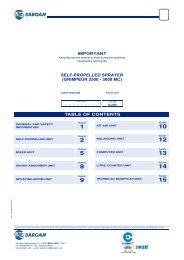
Booklet 3B<br />
<strong>TRAILED</strong> <strong>TANK</strong><br />
user manual<br />
INDEX<br />
Serial number Edition2<br />
01 - 2011<br />
title page title page<br />
TECHNICAL INFORMATION..........................2<br />
Main components ....................................2<br />
Technical specifications ...........................3<br />
Residual volume............................................4<br />
Safety devices .........................................5<br />
Position of signals....................................6<br />
INFORMATION ABOUT HANDLING AND<br />
INSTALLATION...............................................7<br />
Transporting.............................................7<br />
Loading and unloading ............................7<br />
INFORMATION ABOUT ADJUSTMENTS......7<br />
Arm mount adjustment.............................7<br />
Track adjustment .....................................9<br />
Parking brake adjustment......................10<br />
Hydraulic brake adjustment ...................10<br />
CUSHIONED AXLE ADJUSTMENT......10<br />
INFORMATION ABOUT USE .......................12<br />
Instructions for use and operation .........12<br />
Road transport.......................................12<br />
Fixed draw-bar.......................................14<br />
Adjustment of the drawbar height <br />
(3200/4200).................................................14<br />
Adjustment of the drawbar height <br />
(5200/6200).................................................14<br />
Hydraulic steering drawbar....................15<br />
“Straight drawbar" indicator adjustment ......15<br />
How to use the draw-bar .............................15<br />
Computerized drawbar.......................... 16<br />
Installation of the potentiometer ..................16<br />
Using the computerized steering drawbar...16<br />
Basic articulated drawbar with coupling <br />
for height adjuster arms ........................ 17<br />
Adjusting the length of the drawbar arms....17<br />
Adjustment of drawbar brake ......................17<br />
System diagrams .................................. 18<br />
Water system diagram with proportional<br />
control unit...................................................18<br />
Water system diagram with computerized<br />
control unit...................................................19<br />
Water system diagram with centrifugal <br />
pump and computerized control unit ...........20<br />
Tank filling ............................................. 21<br />
Water filling from the upper holes ......... 21<br />
Water filling through tank filling hose..... 22<br />
Filling with centrifugal pump.................. 23<br />
Product mixing ...................................... 24<br />
Spraying ................................................ 24<br />
System washing and emptyng of <br />
residual volume..................................... 26<br />
Without tank inside washing kit ...................27<br />
With tank inside washing kit ........................28<br />
INFORMATION ABOUT <br />
REPLACEMENTS .........................................29<br />
Lubrication points diagram .................... 29<br />
2330091.fm<br />
IMPORTANT SAFETY NOTE<br />
The information published in this booklet regards the<br />
pointed out with relevant symbols in order to safeguard<br />
operational aspects of the operator unit installed<br />
on the people from risks. Remember that prudence is<br />
irreplaceable. machine. It is however necessary that<br />
you carefully read the Safety is also in the hands of all<br />
the operators who interact general safety regulations<br />
published in Booklet 1 and those with the machine.<br />
English<br />
- 1 -<br />
user manual
Trailed tank<br />
Booklet3B<br />
TECHNICAL INFORMATION<br />
MAIN COMPONENTS<br />
233009001-00<br />
2330091.fm<br />
A) Spray product tank.<br />
B) Pump.<br />
C) Water control unit<br />
D) Clean water tank for hand washing.<br />
E) Clean water tank for system washing.<br />
F) Mixer (on request).<br />
H) Pressure gauge to measure the working pressure<br />
of spraying boom.<br />
M1)Fixed draw-bar (3200/4200)<br />
M2)Fixed draw-bar (5200/6200)<br />
M3)Computerised draw-bar (3200/4200)<br />
M4)Computerised draw-bar (5200/6200)<br />
M5)Basic articulated draw-bar with hitch in the lifting<br />
device arms (Version with pump on the frame)<br />
M6)Basic articulated draw-bar with hitch in the lifting<br />
device arms (Version with pump on the drawbar)<br />
English<br />
- 2 -<br />
user manual
Trailed tank<br />
Booklet3B<br />
N) Ramp.<br />
P) Boom lifting device (see booklet “Height adjustment<br />
equipment”).<br />
Q) Pressure gauge to measure pressure of service<br />
water system. If the central spray section closes or<br />
if the pressure gauge (H) breaks down, take an approximate<br />
measurement of the pressure of supply<br />
to the boom.<br />
R) Product basket<br />
S) Manual hydraulic pump for the operation of the support<br />
leg (3200/4200).<br />
T) Water cocks: to select suction, use and washing.<br />
Information concerning components that is not included<br />
in this manual is detailed in the relevant instruction<br />
manuals. The information about the components that<br />
is not included in this manual is detailed in the relevant<br />
instruction manuals.<br />
<br />
TECHNICAL SPECIFICATIONS<br />
Models vary according to drawbar type and tank size.<br />
The table shows the technical features of each model.<br />
The table shows the technical specifications of each<br />
model.<br />
Version with fixed and computerised draw-bar<br />
Model<br />
Capacity (Lt)<br />
Size<br />
A ( 3 ) B C D E F G H<br />
Weight<br />
(kg)<br />
3200 ( 1 ) 3000 1600÷2500 4135 2920 5483 3450 2100 500 1340 2300<br />
4200 ( 1 ) 4000 1600÷2500 4135 2920 5483 3450 2100 500 1340 2300<br />
5200 ( 2 ) 5100 1600÷2500 4800 2884 6540 3450 2100 460÷630 1340 2680<br />
6200 ( 2 ) 6000 1600÷2500 4800 2884 6540 3450 2100 460÷630 1340 2750<br />
( 1 ) The sizes refer to the sprayer with 11.2 R48 (270/<br />
95 R48) wheels and with fixed or steering drawbar.<br />
( 2 ) Sizes refer to type 12,4 R46 sprayer with wheels<br />
(300/95 R46).<br />
( 3 ) The track size depends on the type of tyre and on<br />
the type of hub installed.<br />
233009003-00<br />
2330091.fm<br />
English<br />
- 3 -<br />
user manual
Trailed tank<br />
Booklet3B<br />
Version with basic articulated draw-bar with hitch in the lifting device arms<br />
Model<br />
Capacity (Lt)<br />
Size<br />
A ( 2 ) B C D E F G H<br />
Weight<br />
(kg)<br />
3200 ( 1 ) 3000 1600÷2500 3505÷3745 2920 4845÷5085 3450 2100 750 1340 2350<br />
4200 ( 1 ) 4000 1600÷2500 3505÷3745 2920 4845÷5085 3450 2100 750 1340 2380<br />
( 1 ) The sizes refer to the sprayer with 11.2 R48 (270/<br />
95 R48) wheels and with fixed or steering drawbar.<br />
( 2 ) The track size depends on the type of tyre and on<br />
the type of hub installed.<br />
233009003a-00<br />
Tyre pressure (empty machine): 3.5÷4 bars<br />
Residual volume<br />
The liquid volume that cannot be properly distributed<br />
(technical residue) does not exceed 0.5% of nominal<br />
volume plus 2 litres per boom meter.<br />
The table shows the value of both soluble and non<br />
soluble technical residues.<br />
3200 (Nominal capacity: 3000 litres - Effective capacity: 3200 litres)<br />
4200 (Nominal capacity: 4000 litres - Effective capacity: 4250 litres)<br />
5200 (Nominal capacity: 4800 litres - Effective capacity: 5100 litres)<br />
6200 (Nominal capacity: 6000 litres - Effective capacity: 6300 litres)<br />
Boom length (meters) Soluble * (litres) Non soluble ** (litres) Total (litres)<br />
18 33,1 19,5 52,6<br />
20 33,1 21,1 54,2<br />
21 33,1 21,7 54,8<br />
24 33,1 24,8 57,9<br />
27 33,1 27,9 61<br />
28 33,1 28,9 62<br />
30 33,1 30,2 63,3<br />
32 33,1 32,6 65,7<br />
2330091.fm<br />
33 33,1 33,2 66,3<br />
(*) Soluble technical residue during washing<br />
(**) Non soluble technical residue during washing<br />
English<br />
- 4 -<br />
user manual
Trailed tank<br />
Booklet3B<br />
SAFETY DEVICES<br />
A) Support: to support the supply hoses.<br />
B) Parking brake: to avoid accidental movement of<br />
the machine, activate the brake before switching<br />
off.<br />
C) Handrail: to prevent falls.<br />
D) Stop valve (hydraulic system with solenoid<br />
valve kit): device preventing the boom from dropping<br />
suddenly in the event of a leak in the hydraulic<br />
hose.<br />
E) Protective sheathing: to protect the supply hoses.<br />
F) Cardan shaft guard: to avoid entanglement with<br />
parts of the body.<br />
G) Cardan shaft support: to support the shaft while<br />
disconnected from power take-off.<br />
H) Support leg: to support the equipment before disconnection<br />
so that reconnection is simpler.<br />
L) Ramp locking: to avoid accidental opening.<br />
M) Wheel chocks: to avoid accidental movement of<br />
the vehicle, position chocks before switching off<br />
N) Cock (only for equipment with cushioned axle): To<br />
block the lifting device during the maintenance operation<br />
in the area below<br />
O) Fixed guard: To protect pipes and fittings<br />
P) Lock valve (for hydraulic system with quick cou<br />
plings and single-acting lifting): Device preventing<br />
the boom from dropping suddenly in the event of a<br />
leak in the hydraulic hose<br />
Q) Spraying bar arm support: to avoid accidental<br />
movement, used to lock boom in place during road<br />
transfer.<br />
R) Arm mount for spraying boom: to avoid accidental<br />
movement, used to lock boom in place during<br />
road transfer.<br />
Caution - Warning<br />
Check daily that all safety devices are correctly installed<br />
and in working order.<br />
233009004-00<br />
2330091.fm<br />
English<br />
- 5 -<br />
user manual
Trailed tank<br />
Booklet3B<br />
POSITION OF SIGNALS<br />
The figure shows the location of all safety plates, while<br />
their meaning is explained in booklet 1. <br />
Important<br />
Make sure that all plates are legible. If they are not,<br />
clean or replace, if necessary, ensuring the new ones<br />
are placed in the original position.<br />
233009005-00<br />
2330091.fm<br />
English<br />
- 6 -<br />
user manual
Trailed tank<br />
Booklet3B<br />
INFORMATION ABOUT HANDLING AND INSTALLATION<br />
TRANSPORTING<br />
Loading and transporting can be carried out in different<br />
ways, according to the destination. In all cases the<br />
equipment must not be packaged.<br />
LOADING AND UNLOADING<br />
Danger - Warning<br />
Lifting and handling must be carried<br />
out with the tank empty and using appropriate<br />
equipment, by skilled staff<br />
specialized in this kind of operation.<br />
1 - Prepare a lifting hook with an adequate<br />
loading capacity and connect<br />
as shown in the figure below.<br />
2 - Lift slowly, move very gently and<br />
avoid all swinging.<br />
3 - Load onto the vehicle and secure<br />
using ropes and chocks.<br />
<br />
<br />
233009008-00<br />
INFORMATION ABOUT ADJUSTMENTS<br />
ARM MOUNT ADJUSTMENT<br />
Supports (A and B) can be installed in<br />
positions 1 or 2 depending on the equipment<br />
versions. During transportation,<br />
the track is adjusted to the narrower position<br />
and the supports in the lower position.<br />
To widen the track, it is necessary to adjust<br />
the height of the supports (A and B,<br />
if fitted)<br />
1 - Lift boom above the wheel using<br />
the control.<br />
2330091.fm<br />
233007028-00<br />
English<br />
- 7 -<br />
user manual
Trailed tank<br />
Booklet3B<br />
2 - Loosen the screws (C) and adjust<br />
the position of the supports at the<br />
corresponding holes, so that the<br />
seat (D) rests on the roller (E).<br />
Important<br />
The supports must be placed so that<br />
they are secured by at least three<br />
screws (C).<br />
233007029-00<br />
Only for the version with hydraulic<br />
booms with lateral folding<br />
3 - Install lateral supports (G) and fasten<br />
them with screws (F).<br />
2330091.fm<br />
233007071-00<br />
English<br />
- 8 -<br />
user manual
Trailed tank<br />
Booklet3B<br />
TRACK ADJUSTMENT<br />
Caution - Warning<br />
Carry out this operation on flat<br />
ground, with the equipment hitched to<br />
the tractor, parking brake set and an<br />
empty tank.<br />
1 - Lift the axle slightly using the special<br />
device and line it up with the<br />
data plate (B).<br />
Important<br />
Determine whether it is easier to turn<br />
the wheel over and/or loosen or tighten<br />
the axle.<br />
2 - Loosen screws (A) and adjust<br />
track.<br />
Caution - Warning<br />
The maximum extension allowed is<br />
limited by the three screws (A); more<br />
precisely, the extension tube must be<br />
secured at all times by the three screws (A) together.<br />
233009009-00<br />
3 - Tighten screws (A).<br />
4 - Repeat on the opposite axle.<br />
Caution - Warning<br />
After a short distance (~1 km), tighten<br />
the wheel screws and nuts once more.<br />
Narrow track<br />
Wide track<br />
233009010-00<br />
2330091.fm<br />
English<br />
- 9 -<br />
user manual
Trailed tank<br />
Booklet3B<br />
PARKING BRAKE ADJUSTMENT<br />
Caution - Warning<br />
Carry out this operation on flat ground, with the<br />
equipment hitched to the tractor, parking brake set<br />
and an empty tank.<br />
1 - Lift the axle using the special device and line it up<br />
with the data plate so that the wheel no longer<br />
touches the ground.<br />
2 - Adjust the lever (B) to position 1; the wheel should<br />
turn freely.<br />
3 - Bring the lever (B) to position 2; the wheel should<br />
be completely locked.<br />
4 - Adjust the register of the corresponding wheel to<br />
get the best position from the two phases<br />
explained above and then tighten the lock nut (C)<br />
at the end of this operation.<br />
5 - Repeat this procedure for the other wheel.<br />
233009011-00<br />
HYDRAULIC BRAKE ADJUSTMENT<br />
Important<br />
This operation must be carried out<br />
while the parking brake is released.<br />
To increase braking speed, turn valve<br />
(A) anticlockwise and reduce by turning<br />
clockwise.<br />
233009012-00<br />
CUSHIONED AXLE ADJUSTMENT<br />
2330091.fm<br />
Important<br />
Carry out this operation in order toobtain the best<br />
cushioning withempty and fully loaded equipment.The<br />
adjustment must be carried outwith the<br />
boom folded in transportposition and when the<br />
equipment isempty..<br />
English<br />
- 10 -<br />
user manual
Trailed tank<br />
Booklet3B<br />
Adjustment of shock absorbers must<br />
be carried out with a folded boom and<br />
empty tank.<br />
1 - Remove caps (A) and connect<br />
thepump hoses to cocks (B-C).<br />
<br />
<br />
<br />
<br />
<br />
<br />
<br />
<br />
<br />
2 - Connect pressure gauge (D) to<br />
pressure intake (E).<br />
3 - Open valve (C) and pump oil until<br />
approx. pressure of 85 bars is<br />
reached.<br />
<br />
<br />
<br />
<br />
<br />
<br />
<br />
<br />
4 - Close valve (C) and release pump<br />
pressure through knob (F).<br />
<br />
<br />
<br />
<br />
<br />
<br />
<br />
<br />
<br />
<br />
<br />
233009013-00<br />
233009014-00<br />
2330091.fm<br />
5 - Connect pressure gauge (D) to<br />
pressure intake (G).<br />
6 - Open valve (B) and pump oil until<br />
approx. pressure of 122 bars is<br />
reached.<br />
<br />
<br />
<br />
<br />
<br />
<br />
<br />
233009015-00<br />
233009016-00<br />
English<br />
- 11 -<br />
user manual
Trailed tank<br />
Booklet3B<br />
7 - Close cock (B) and discharge thepressure<br />
by means of knob (F).<br />
<br />
<br />
<br />
<br />
<br />
<br />
<br />
<br />
<br />
<br />
<br />
<br />
233009017-00<br />
8 - Open cock (C) and discharge the<br />
oilup to the cylinder extension<br />
of11cm.<br />
233009018-00<br />
INFORMATION ABOUT USE<br />
INSTRUCTIONS FOR USE AND OPERATION<br />
All the general information concerning the use of the<br />
tractor is in the special booklet, which describes all the<br />
specific information of the different parts of the equipment.<br />
ROAD TRANSPORT<br />
Road transport is allowed ONLY to approved<br />
equipment and to tractor drivers who have the<br />
necessary requirements according to the laws in<br />
force.<br />
Important<br />
Road transport is allowed only when the equipment<br />
is completely empty.<br />
In any case, before transport:<br />
- lock the parts that may cause sudden and unexpected<br />
movements.<br />
- make sure that the equipment does not exceed the<br />
maximum permitted overall dimensions.<br />
- if necessary, provide the equipment with the special<br />
signals.<br />
- Completely empty the tank.<br />
Caution - Warning<br />
If the equipment is approved for road transport with<br />
filled tank, the liquid shall not be mixed with the<br />
chemical products to be strayed.<br />
2330091.fm<br />
English<br />
- 12 -<br />
user manual
Trailed tank<br />
Booklet3B<br />
- Adjust the drawbar to the minimum<br />
length (see illustration).<br />
- Make sure that the equipment is<br />
properly connected to the tractor.<br />
- Make sure that the tractor power<br />
take-off is disconnected.<br />
- Make sure that the boom is properly<br />
closed and positioned on its supports.<br />
- Deactivate the control board.<br />
233007086-00<br />
Important<br />
Road transport requires the knowledge<br />
and the observance of the regulations contained<br />
in the manual "Road transport regulations".<br />
<br />
<br />
<br />
If the equipment is approved for road<br />
transport with filled tank proceed as follows:<br />
1 - Loosen knobs (A) of the rear<br />
reflectors.<br />
2 - Remove safety pin (B)<br />
3 - Loosen knobs (A) of the rear<br />
reflectors and lower support (C)<br />
until it stops onto pin (D)<br />
4 - Introduce safety pins (B) into hole<br />
(E).<br />
5 - Tighten knobs (A).<br />
<br />
<br />
<br />
<br />
<br />
233007035-00<br />
6 - Loosen knobs (F) of front reflector<br />
supports (G).<br />
7 - Adjust reflectors (G) at a width of<br />
2100 mm and tighten knobs (F).<br />
2330091.fm<br />
<br />
<br />
<br />
<br />
<br />
<br />
233009029-00<br />
English<br />
- 13 -<br />
user manual
Trailed tank<br />
Booklet3B<br />
FIXED DRAW-BAR<br />
Adjustment of the drawbar height (3200/4200)<br />
Caution - Warning<br />
During this operation the equipment<br />
must be in horizontal position and the<br />
tank must be empty; the wheels and<br />
the system must be blocked according<br />
to the figure.<br />
1 - Loosen screws (E);<br />
2 - Unscrew and remove screw (F);<br />
3 - Lift or lower drawbar to coincide<br />
with one of the three holes still<br />
available;<br />
4 - Replace screw (F) and tighten;<br />
5 - Tighten screws (E);<br />
<br />
<br />
<br />
<br />
<br />
<br />
233009030-00<br />
Adjustment of the drawbar height (5200/6200)<br />
If the height of the tractor hook does not coincide with<br />
the eyelet, adjust the height of the drawbar as follows.<br />
1 - Loosen the screws (A).<br />
2 - Lift, lower and rotate plate (B), if necessary, until<br />
the desired height is obtained (see diagram).<br />
Note: Sizes refer to type 12,4 R46 sprayer with<br />
wheels (300/95 R46).<br />
3 - Screw screws (A).<br />
2330091.fm<br />
233009021-00<br />
English<br />
- 14 -<br />
user manual
Trailed tank<br />
Booklet3B<br />
HYDRAULIC STEERING DRAWBAR<br />
“Straight drawbar" indicator adjustment<br />
1 - Place the drawbar end-piece (A)<br />
so that it is perfectly aligned with<br />
the frame (B).<br />
<br />
233007042-00<br />
2 - Loosen the clamp (C) and place it<br />
on the white indicator (D).<br />
3 - Tighten the clamp (C) when adjustment<br />
is completed.<br />
233007043-00<br />
How to use the draw-bar<br />
The articulated drawbar can be adjusted<br />
using the hydraulic cylinder (B) so<br />
that the tank follows the tractor around<br />
bends and crosswise on slopes.<br />
Important<br />
Before using the steering drawbar,<br />
disconnect the tie-rod (C) and lay it in<br />
the rest position (2).<br />
233009033-00<br />
2330091.fm<br />
Danger - Warning<br />
Opening and closing the steering drawbar cylinder<br />
should only be done when the spray boom is completely<br />
unfolded. If this condition is not met, the tank<br />
may overturn.<br />
Important<br />
Before road transfer, the drawbar MUST be locked<br />
using the tie-rod (C) (position 1).<br />
English<br />
- 15 -<br />
user manual
Trailed tank<br />
Booklet3B<br />
COMPUTERIZED DRAWBAR<br />
Installation of the potentiometer<br />
1 - Install gyroscope support (A) on the back of the in<br />
vertical position. After installation, make sure that<br />
the support is free from swinging.<br />
2 - Connect gyroscope support (B) to support (A) by<br />
means of screws (C).<br />
Important<br />
The caption "TOP - OBEN" must be positioned on<br />
top. <br />
The gyroscope works correctly only if it is installed<br />
in a vertical position and if, during operation, it is in<br />
a fixed position on the tractor and does not swing.<br />
233007037-00<br />
3 - If necessary, install the bushing (G) and check<br />
that it lines up perfectly with both pin and tractor<br />
hitch pin. If not, adjust.<br />
Important<br />
Clearance between eyelet and pin, which would jeopardize<br />
correct functioning of the drawbar.<br />
<br />
<br />
233007038-00<br />
Using the computerized steering drawbar<br />
When the tie-rod (C) is in position (1),<br />
the drawbar articulation is locked and<br />
the automatic steering control device is<br />
disabled by the sensor (D).<br />
Disconnect the tie-rod (C) and place it<br />
in position (2), to reactivate the automatic<br />
steering control device from the<br />
control panel (see enclosed computer<br />
booklet).<br />
Steering is controlled by the cylinder<br />
(B).<br />
Danger - Warning<br />
Opening and closing the steering<br />
drawbar cylinder should only be done when the<br />
spray boom is completely unfolded. If this condition<br />
is not met, the tank may overturn.<br />
233009025-00<br />
2330091.fm<br />
English<br />
- 16 -<br />
user manual
Trailed tank<br />
Booklet3B<br />
BASIC ARTICULATED DRAWBAR WITH COUPLING FOR HEIGHT ADJUSTER<br />
ARMS<br />
Adjusting the length of the drawbar<br />
arms<br />
Proceed as follows:<br />
1 - Unscrew the screws (A).<br />
2 - Adjust the clamps (B) as necessary.<br />
3 - Tighten screws (A).<br />
Adjustment of drawbar brake<br />
1 - Loosen screws (A)<br />
2 - Use screws (B) so that the brake<br />
pads create friction on the disc.<br />
Move draw-bar manually in order to<br />
determine the desired friction level.<br />
3 - Tighten screws (A)<br />
233009031-00<br />
Important<br />
do not tighten screws (B) to an extent<br />
that blocks the movement of the halfdisc.<br />
233009032-00<br />
2330091.fm<br />
English<br />
- 17 -<br />
user manual
Trailed tank<br />
Booklet3B<br />
SYSTEM DIAGRAMS<br />
Water system diagram with proportional control unit<br />
Legend<br />
37<br />
233009038-00<br />
1 - Suction filter (filling)<br />
3 - Litre counter (filling)<br />
4 - Tank emptying valve<br />
5 - 3-way ball valve<br />
6 - Stainless steel manifold<br />
7 - Suction filter<br />
8 - Diaphragm pump<br />
9 - Maximum pressure control valve<br />
10 - 3-way ball valve<br />
11 - Product transfer valve<br />
12 - Container washing lever-operated<br />
con- trol valve<br />
13 - Mixer<br />
14 - Control unit line filter<br />
15 - Pressure control engine<br />
16 - Main engine<br />
17 - Tank inside washing valve<br />
18 - Water supply litre counter<br />
19 - Tap assembly<br />
20 - Solenoid valve assembly<br />
21 - Stainless steel pipes<br />
22 - Equipment washing valve<br />
23 - Hose reel for equipment washing<br />
25 - Equipment washing spray gun<br />
26 - Clear water suction valve<br />
27 - 3-way ball valve<br />
28 - Distribution line filters<br />
29 - Clear water tank<br />
30 - Product tank<br />
33 - Control unit<br />
34 - Non return valve<br />
35 - Pressure gauge<br />
36 - Working pressure gauge<br />
37 - 5 ways valve<br />
2330091.fm<br />
English<br />
- 18 -<br />
user manual
Trailed tank<br />
Booklet3B<br />
Water system diagram with computerized control unit<br />
18<br />
37<br />
233009037-00<br />
Legend<br />
1 - Suction filter (filling)<br />
3 - Litre counter (filling)<br />
4 - Tank emptying valve<br />
5 - 3-way ball valve<br />
6 - Stainless steel manifold<br />
7 - Suction filter<br />
8 - Diaphragm pump<br />
9 - Maximum pressure control valve<br />
10 - 3-way ball valve<br />
11 - Product transfer valve<br />
12 - Container washing lever-operated<br />
con- trol valve<br />
13 - Mixer<br />
14 - Control unit line filter<br />
15 - Pressure control engine<br />
16 - Main engine<br />
17 - Tank inside washing valve<br />
18 - Water supply litre counter<br />
19 - Tap assembly<br />
20 - Solenoid valve assembly<br />
21 - Stainless steel pipes<br />
22 - Equipment washing valve<br />
23 - Hose reel for equipment washing<br />
25 - Equipment washing spray gun<br />
26 - Clear water suction valve<br />
27 - 3-way ball valve<br />
28 - Distribution line filters<br />
29 - Clear water tank<br />
30 - Product tank<br />
33 - Control unit<br />
35 - Pressure gauge<br />
36 - Working pressure gauge<br />
37 - 5 ways valve<br />
2330091.fm<br />
English<br />
- 19 -<br />
user manual
Trailed tank<br />
Booklet3B<br />
Water system diagram with centrifugal pump and computerized control unit<br />
18<br />
Legend<br />
37<br />
233009039-00<br />
1 - Suction filter (filling)<br />
2 - Centrifugal pump (filling)<br />
3 - Litre counter (filling)<br />
4 - Tank emptying valve<br />
5 - 3-way ball valve<br />
6 - Stainless steel manifold<br />
7 - Suction filter<br />
8 - Diaphragm pump<br />
9 - Maximum pressure control valve<br />
10 - 3-way ball valve<br />
11 - Product transfer valve<br />
12 - Container washing lever-operated<br />
con- trol valve<br />
13 - Mixer<br />
14 - Control unit line filter<br />
15 - Pressure control engine<br />
16 - Main engine<br />
17 - Tank inside washing valve<br />
18 - Water supply litre counter<br />
19 - Tap assembly<br />
20 - Solenoid valve assembly<br />
21 - Stainless steel pipes<br />
22 - Equipment washing valve<br />
23 - Hose reel for equipment washing<br />
25 - Equipment washing spray gun<br />
26 - 3-way ball valve<br />
27 - Clear water suction valve<br />
28 - Distribution line filters<br />
29 - Clear water tank<br />
30 - Product tank<br />
32 - Clear water tank filling valve<br />
33 - Control unit<br />
35 - Pressure gauge<br />
36 - Working pressure gauge<br />
37 - 5 ways valve<br />
2330091.fm<br />
English<br />
- 20 -<br />
user manual
Trailed tank<br />
Booklet3B<br />
<strong>TANK</strong> FILLING<br />
The tank can be filled in two different ways:<br />
- Water filling from the upper holes (page 21);<br />
- Water filling through tank filling hose (page 22);<br />
- Filling with centrifugal pump (page 23);<br />
Important<br />
When filling the tank, ensure that hand-washingtank<br />
(C) has been filled with clean water and filledit up, if<br />
necessary.<br />
WATER FILLING FROM THE UPPER HOLES<br />
Use an external water source or a tank<br />
that is located on a level higher than<br />
filling hole (A and B).<br />
Fill tank (C) with hand-washing water<br />
Important<br />
Tank filling opening (B) must be<br />
equipped with the basket filter (mesh<br />
size 1 mm).<br />
Important<br />
The tank (A) must be filled with clean<br />
water.<br />
233009022-00<br />
2330091.fm<br />
English<br />
- 21 -<br />
user manual
Trailed tank<br />
Booklet3B<br />
WATER FILLING THROUGH <strong>TANK</strong> FILLING HOSE<br />
L<br />
2<br />
1<br />
C<br />
233007049-00<br />
2330091.fm<br />
Caution - Warning<br />
Make sure that no part of the tank-filling hose comes<br />
into contact with the chemical spray products, so<br />
that the water source does not become polluted.<br />
1 - Plunge floating filter (G) into the water source<br />
(reservoir, external tank, ditch, etc).<br />
2 - Remove the cap (A) from the coupling (C).<br />
3 - Connect the tank-filling hose (B) to the coupling (C).<br />
4 - Place the valve levers (E-F-H) in the position<br />
shown. Turn valve levers (L) to position 2.<br />
5 - Connect the PTO.<br />
6 - To fill the clear water tank, turn valve lever (L) to<br />
position 1.<br />
7 - When filling is over, return lever to position 2.<br />
8 - Reduce the power take-off rpm.<br />
English<br />
- 22 -<br />
user manual
Trailed tank<br />
Booklet3B<br />
9 - Turn valve levers (H) to position 2.<br />
10- When the operation is over, disconnect the hose<br />
(B) and replace the cap (A). The machine is ready<br />
to start spraying.<br />
<br />
<br />
FILLING WITH CENTRIFUGAL PUMP<br />
233009035-00<br />
233009034-00<br />
2330091.fm<br />
Proceed as follows.<br />
1 - Remove cap (A).<br />
2 - Connect the hose (B) to the coupling (C).<br />
Caution - Warning<br />
Make sure that no part of the tank- filling hose comes<br />
into contact with the chemical spray products, so<br />
that the water source does not become polluted.<br />
3 - Plunge floating filter (G) into the water source<br />
(reservoir, external tank, ditch, etc).<br />
4 - Connect the PTO.<br />
5 - To fill the clear water tank, turn valve lever (D) to<br />
position 1.<br />
6 - Reduce the power take-off rpm.<br />
7 - When the operation is over, disconnect the hose<br />
(B) and replace the cap (A).<br />
English<br />
- 23 -<br />
user manual
Trailed tank<br />
Booklet3B<br />
PRODUCT MIXING<br />
L<br />
233007051-00<br />
To mix the product, follow the procedure below:<br />
1 - Make sure that the system is clean and pour the<br />
necessary water for the treatment into the main<br />
tank (see page 22 water filling with tank filling<br />
hose).<br />
If the main tank contains a suitable quantity of<br />
water, go on to the following steps with valve lever<br />
(H) in position 2<br />
2 - Lower the Mixer in order to facilitate the product<br />
preparation steps<br />
3 - Place the valve levers (L) in the position shown.<br />
4 - Activate the pump.<br />
5 - Carry out the operations for the preparation and<br />
mixing of the chemical (see leaflet 5).<br />
6 - When the operation is complete, raise the mixer.<br />
SPRAYING<br />
2330091.fm<br />
Important<br />
The environment and field conditions of the area<br />
where you plan to operate have to be checked every<br />
time the equipment is set up for spraying.<br />
Evaluate the following requirements.<br />
- Check whether or not there are electric lines and<br />
assess the risks of contact with the spraying<br />
booms.<br />
- Check the gradient of the land so as to evaluate the<br />
most suitable conditions for operating in safety.<br />
Always bear in mind the maximum gradients<br />
allowed.<br />
English<br />
- 24 -<br />
user manual
Trailed tank<br />
Booklet3B<br />
L<br />
233007053-00<br />
2330091.fm<br />
- In the event of spraying while moving crosswise to<br />
the slope, follow the instructions extremely carefully:<br />
Boom unfolding stage: always unfold the uphill<br />
boom first, and then the downhill boom.<br />
Boom folding stage: always fold the downhill boom<br />
first, and then the uphill boom.<br />
- Never leave the downhill boom alone unfolded.<br />
- Keep the forward speed moderate (max. 8-10 km/<br />
h) to prevent the booms from swinging and to keep<br />
spraying even.<br />
- Before you start spraying an area, make sure there<br />
is enough product in the tank.<br />
- It is important to be up to date with the weather<br />
conditions while spraying. Wind speed should not<br />
exceed 5m/sec.<br />
Proceed as follows for spraying:<br />
1 - Place valve levers (E-F-H-L) in the position<br />
shown.<br />
2 - Connect the tractor PTO (max. 540rpm).<br />
3 - Unfold the spraying boom.<br />
4 - Select the sections of the boom that correspond to<br />
the area to be sprayed.<br />
5 - Use the switch of the control board to supply the<br />
boom and start the tractor<br />
Important<br />
If it is windy, (even below the maximum limit of 5 m/<br />
sec) to prevent the product from drifting, keep the<br />
boom low and increase the size of the droplets.<br />
Danger - Warning<br />
Prevent outsiders from approaching the working<br />
area when the equipment is in use. If necessary, stop<br />
spraying immediately and get the people in the risk<br />
area to move away.<br />
English<br />
- 25 -<br />
user manual
Trailed tank<br />
Booklet3B<br />
SYSTEM WASHING AND EMPTYNG OF RESIDUAL VOLUME<br />
L<br />
233007054-00<br />
Caution - Warning<br />
Pollutant substances must be properly disposed of<br />
in compliance with current legislation. Special care<br />
should be taken to avoid polluting waterways and<br />
groundwater with spraying chemicals. Keep product<br />
out of reach of children.<br />
- Pour clean water into the tank, diluting residual<br />
product in a ratio of 1:10.<br />
- Spray all the retrievable product onto a surface.<br />
Washing and emptying of the residual volume may be<br />
carried out in various ways according to the set-up of<br />
the machine.<br />
- Without tank inside washing kit.<br />
- With tank inside washing kit.<br />
Important<br />
Residual volume is the leftover liquid that cannot be<br />
suctioned up and remains on the bottom of the tank.<br />
2330091.fm<br />
English<br />
- 26 -<br />
user manual
Trailed tank<br />
Booklet3B<br />
Without tank inside washing kit<br />
1 - Place valve levers (E-F-H-L) in the<br />
position shown.<br />
2 - Remove the main lid of the tank<br />
and clean the walls with a jet of<br />
water.<br />
L<br />
Important<br />
Bear in mind that there must be a 1:10<br />
ratio between the residual volume and<br />
the water used for cleaning.<br />
3 - Start the water pump.<br />
4 - Wash the Mixer and pipes (see<br />
Mixer booklet).<br />
5 - Set machine up for spraying (see<br />
"Spraying" page 24).<br />
6 - Spray all retrievable liquid onto an<br />
area to be treated.<br />
7 - Remove the cap (Z), place a receptacle<br />
beneath the valve (V) and<br />
open the lever to drain off the residual<br />
liquid.<br />
8 - Close the lever again (V) and<br />
replace the cap (Z).<br />
Z<br />
V<br />
233009023-00<br />
2330091.fm<br />
English<br />
- 27 -<br />
user manual
Trailed tank<br />
Booklet3B<br />
With tank inside washing kit<br />
1 - Place valve levers (E-F-H-L) in the<br />
position shown.<br />
2 - Connect the PTO for ~ 5 sec. and<br />
bring the valve lever (G) to position<br />
1 to wash the inside walls.<br />
3 - Return the valve lever (G) to position<br />
2.<br />
L<br />
Important<br />
Bear in mind that there must be a 1:10<br />
ratio between the residual volume and<br />
the water used for cleaning.<br />
4 - Wash the Mixer and pipes (see<br />
Mixer booklet).<br />
5 - Set machine up for spraying (see<br />
"Spraying" page 24).<br />
6 - Spray all retrievable liquid onto an<br />
area to be treated.<br />
Z<br />
7 - Remove the cap (Z), place a<br />
receptacle beneath the valve (V)<br />
and open the lever to drain off the<br />
residual liquid.<br />
8 - Close the lever again (V) and<br />
replace the cap (Z).<br />
9 - Open valve (M) to clean filter (N).<br />
10- Remove the intake filter (P), mesh<br />
size 0.25 mm, and wash it with a<br />
water jet.<br />
11- Remove the in-line bar filters (see<br />
leaflet 9) and wash them with a<br />
water jet.<br />
12- Wash the outside of the tanks and<br />
the areas in contact with the product<br />
with a water jet.<br />
V<br />
2330091.fm<br />
233009040-00<br />
English<br />
- 28 -<br />
user manual
Trailed tank<br />
Booklet3B<br />
INFORMATION ABOUT REPLACEMENTS<br />
LUBRICATION POINTS DIAGRAM<br />
Oil all greasing points and sliding surfaces, particularly<br />
whenever the system is washed.<br />
233009036-00<br />
Use PERSIAN POLIGREASE 2 grease<br />
<br />
2330091.fm<br />
English<br />
- 29 -<br />
user manual
Trailed tank<br />
Booklet3B<br />
2330091.fm<br />
English<br />
- 30 -<br />
user manual