DMT testing for redesign using shallow foundations - Marchetti DMT
DMT testing for redesign using shallow foundations - Marchetti DMT
DMT testing for redesign using shallow foundations - Marchetti DMT

You also want an ePaper? Increase the reach of your titles
YUMPU automatically turns print PDFs into web optimized ePapers that Google loves.
PROCEEDINGS FROM THE SECOND INTERNATIONAL FLAT DILATOMETER CONFERENCE<br />
<strong>DMT</strong> <strong>testing</strong> <strong>for</strong> <strong>redesign</strong> <strong>using</strong> <strong>shallow</strong> <strong>foundations</strong><br />
Roger Failmezger<br />
In-Situ Soil Testing, L.C., 173 Dillin Drive, Lancaster, Virginia 22503, email: insitusoil@prodigy.net<br />
Paul Till<br />
Hardin-Kight Associates, Inc., 12515 Caterpillar Lane, Bishopville, Maryland 21813, email: PTillHKA@aol.com<br />
Keywords: Dilatometer, standard penetration test, settlement, case studies<br />
ABSTRACT: Yes, the United States has far too many lawyers, and geotechnical engineers worry about their<br />
liability. But, when geotechnical engineers recommend costly foundation solutions because they don’t have<br />
accurate enough data, we are making inexcusable errors and are not serving the owner’s needs. Dilatometer<br />
tests provide engineers with high quality data so that they can make good foundation design decisions. Presented<br />
in this paper are several case studies showing how dilatometer tests and analyses resulted in much<br />
more economical foundation design solutions than in the originally proposed solutions.<br />
1 INTRODUCTION<br />
Engineers in the U.S. often use standard penetration<br />
<strong>testing</strong> as the only method of investigating a project<br />
site. Laboratory consolidation <strong>testing</strong> is routinely<br />
omitted either due to too small of a <strong>testing</strong> fee or<br />
sands that are difficult to sample. Because of the<br />
high uncertainty in defining and understanding the<br />
de<strong>for</strong>mation characteristics of the soil, the engineer<br />
becomes overly conservative with his design. Un<strong>for</strong>tunately,<br />
many engineers are often reluctant to<br />
ask the owner to pay <strong>for</strong> additional investigations after<br />
they know that they need them to do good design.<br />
Faced with expensive foundation recommendations<br />
that the owner is not sure he needs, the owner will<br />
lose confidence in the first engineer and often ask<br />
another engineer to <strong>redesign</strong> the foundation. As the<br />
second engineers, we per<strong>for</strong>med subsurface investigations<br />
<strong>using</strong> dilatometer tests to characterize the de<strong>for</strong>mation<br />
characteristics of the soils better and provide<br />
much more economical yet safe designs.<br />
2 REVIEW OF SPT SETTLEMENT<br />
PREDICTION<br />
2.1 SPT Procedure<br />
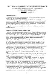
The standard penetration test (SPT) is a dynamic<br />
penetration test that strains the soil to much higher<br />
levels than what structures impose on the underlying<br />
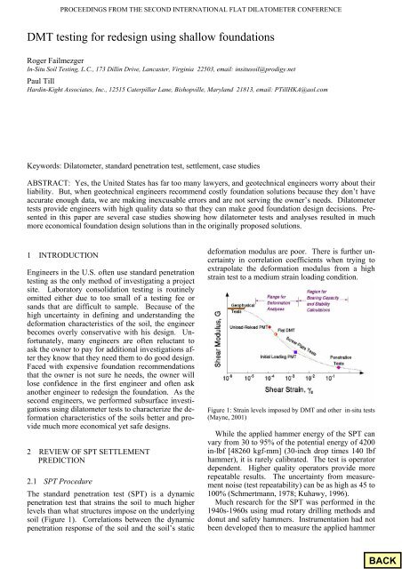
soil (Figure 1). Correlations between the dynamic<br />
penetration response of the soil and the soil’s static<br />
de<strong>for</strong>mation modulus are poor. There is further uncertainty<br />
in correlation coefficients when trying to<br />
extrapolate the de<strong>for</strong>mation modulus from a high<br />
strain test to a medium strain loading condition.<br />
Figure 1: Strain levels imposed by <strong>DMT</strong> and other in-situ tests<br />
(Mayne, 2001)<br />
While the applied hammer energy of the SPT can<br />
vary from 30 to 95% of the potential energy of 4200<br />
in-lbf [48260 kgf-mm] (30-inch drop times 140 lbf<br />
hammer), it is rarely calibrated. The test is operator<br />
dependent. Higher quality operators provide more<br />
repeatable results. The uncertainty from measurement<br />
noise (test repeatability) can be as high as 45 to<br />
100% (Schmertmann, 1978; Kuhawy, 1996).<br />
Much research <strong>for</strong> the SPT was per<strong>for</strong>med in the<br />
1940s-1960s <strong>using</strong> mud rotary drilling methods and<br />
donut and safety hammers. Instrumentation had not<br />
been developed then to measure the applied hammer<br />
91<br />
S
PROCEEDINGS FROM THE SECOND INTERNATIONAL FLAT DILATOMETER CONFERENCE<br />
energy. Researchers believe the applied hammer<br />
energies were about 55 to 60% of the potential energy.<br />
Skempton (1986) proposed correcting the SPT<br />
N-value to an N 60 -value, representing a 60% applied<br />
hammer energy. However, even today it has been<br />
rare to find N 60 values shown on boring logs in the<br />
U.S.<br />
Many newer SPT drill rigs use automatic hammers.<br />
Many of these hammers, provided that they<br />
are well maintained, consistently deliver 90 to 95%<br />
of the SPT potential energy. Without making the<br />
N 60 correction, the N-value from the automatic<br />
hammer will be about 2/3 of the N-value from a<br />
safety hammer.<br />
In the 1940s-1960s the inner diameter of the barrel<br />
of the SPT spoon was the same as the tip. Today,<br />
the inner barrel has an inside diameter that is larger<br />
than the tip inside diameter, which allows liners to<br />
be inserted in the barrel. Without liners, the frictional<br />
resistance along the inside of the spoon is<br />
greatly reduced. While the reduction in resistance<br />
depends on soil conditions, Skempton (1986) suggests<br />
that an average reduction of 20% occurs.<br />
When a borehole is made <strong>using</strong> hollow-stem augers,<br />
the pre-existing geostatic stresses are removed.<br />
When a borehole is made <strong>using</strong> mud rotary drilling,<br />
about half of the pre-existing geostatic stresses are<br />
removed. Reductions in the pre-existing geostatic<br />
stresses soften or loosen the soils and result in lower<br />
N-values.<br />
With today’s methods and without the N 60 correction,<br />
the uncorrected N-values can be ½ of the N-<br />
value measured during the 1940s-1960s. Yet, geotechnical<br />
engineers will often use their uncorrected<br />
N-values with the design methods from that era. As<br />
a result, they are misled into believing the soils are<br />
much weaker than they actually are.<br />
2.2 SPT Design Methods <strong>for</strong> Settlement<br />
In sands Burland and Burbridge (1985) developed<br />
the following equation to predict settlement <strong>using</strong><br />
the SPT:<br />
S = B 0.75 {1.7/(N 60AVG ) 1.4 }(q-2/3σ vo ’)<br />
where S= predicted settlement (mm),<br />
B= footing width (m),<br />
q = applied bearing pressure (kPa),<br />
σ vo ’ = initial effective vertical stress at the base of<br />
the footing level (kPa),<br />
and N 60AVG = average SPT blow count within a<br />
depth of B 0.75 meters beneath the footing.<br />
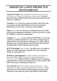
Their case study database revealed the following<br />
graph (Figure 2) of predicted and measured settlement.<br />
SANDS ONLY<br />
Fiure 2: Predicted vs. Measured Settlement from SPT in Sands<br />
Only (Burland and Burbridge (1985).<br />
Based on the Burland and Burbridge (1985) equation,<br />
Duncan (2000) presented a settlement example<br />
that showed that an average settlement of 0.3 inches<br />
[7.6 mm] was required <strong>for</strong> the structure to have less<br />
than 1.0 inch [25 mm] of settlement. Duncan (2000)<br />
showed that the coefficient of variation (standard<br />
deviation/average value) was 0.67 <strong>for</strong> the Burland<br />
and Burbridge (1985) method. Failmezger (2001)<br />
showed that when measurement noise (test repeatability)<br />
and spatial (site subsurface variability) are<br />
considered in addition to the method error, the average<br />
settlement such that settlement would not likely<br />
exceed 1.0 inch [25 mm] is less than 0.3 inches [7.6<br />
mm].<br />
Engineers may use other design charts or correlations<br />
to predict settlement in sands and even other<br />
soil types. SPT tests in clay and residual soils destroy<br />
the soil structure and will often result in low<br />
“N” values that may only be representative of remolded<br />
properties instead of intact properties. The<br />
accuracy with these methods will be even less than<br />
the Burland and Burbridge (1985) method.<br />
In summary, settlement predictions based on SPT<br />
are too inaccurate to be used <strong>for</strong> design.<br />
3 REVIEW OF <strong>DMT</strong> SETTLEMENT<br />
PREDICTION<br />
Schmertmann (1986) developed his ordinary and<br />
special methods <strong>for</strong> computing settlement of a structure<br />
or embankment. The ordinary method is simply<br />
the increase stress multiplied by the layer thickness<br />
divided by the constrained de<strong>for</strong>mation modulus. In<br />
his special method the modulus is adjusted to account<br />
<strong>for</strong> whether the increase stress occurs below<br />
the preconsolidation pressure (highly overconsolidated<br />
soil), above the preconsolidation pressure<br />
(normally consolidated soil) or starts below the preconsolidation<br />
pressure and then exceeds it (lightly<br />
92
PROCEEDINGS FROM THE SECOND INTERNATIONAL FLAT DILATOMETER CONFERENCE<br />
overconsolidated soil). Generally, settlement prediction<br />
from the ordinary method is within 10% of the<br />
special method. Using his 16 case studies, Schmertmann<br />
(1986) had an average predicted to measured<br />
ratio of 1.18 with a standard deviation of 0.38. If the<br />
predictions where the dilatometer blade was driven<br />
and where tests were per<strong>for</strong>med in quick clayey silts<br />
are excluded from the data set, the average predicted<br />
to measured ratio reduces to 1.07 with a standard<br />
deviation of 0.22.<br />
From dilatometer test data, Hayes (1986) computed<br />
settlement at 5 sites <strong>using</strong> Schmertmann’s<br />
(1986) methods. From his case studies with the ordinary<br />
method, the average predicted to measured<br />
ratio was 1.02 with a standard deviation of 0.14 and<br />
<strong>for</strong> the special method, the average predicted to<br />
measured ratio was 1.06 with a standard deviation of<br />
0.25. If we use all the case study data and exclude<br />
the data <strong>for</strong> the quick clayey silts and driven <strong>DMT</strong><br />
data, the average predicted to measured ratio is 1.06<br />
and its standard deviation is 0.18. A summary graph<br />
(Figure 3) from these researchers is shown below:<br />
PREDICTED SETTLEMENT (mm)<br />
2000<br />
1000<br />
500<br />
200<br />
100<br />
50<br />
20<br />
10<br />
5<br />
2<br />
ALL SOILS<br />
1<br />
1 2 5 10 20 50 100 200 500 1000 2000<br />
MEASURED SETTLEMENT (mm)<br />
Figure 3: Predicted vs. Measured Settlement from <strong>DMT</strong> in All<br />
Soils (adapted from Schmertmann, 1986) and Hayes, 1986)<br />
4 CASE STUDIES<br />
Five case studies are presented below that demonstrate<br />
the value of <strong>using</strong> dilatometer test data <strong>for</strong> design.<br />
In each case the <strong>redesign</strong> saved the owners between<br />
US $200,000 and US $800,000. Each<br />
building is per<strong>for</strong>ming to the satisfaction of the<br />
owners. A summary of the original design and the<br />
<strong>redesign</strong> based on dilatometer <strong>testing</strong> is shown in<br />
Table 1.<br />
Table 1: Summary of Foundation Redesign Case Studies<br />
93
PROCEEDINGS FROM THE SECOND INTERNATIONAL FLAT DILATOMETER CONFERENCE<br />
4.1 Westminister Village<br />
In the first geotechnical investigation program, soil<br />
test borings showed 7 to 13 feet [2.1 to 4.0 m] of<br />
sand underlain by a soft to medium stiff clay. One<br />
laboratory consolidation test was per<strong>for</strong>med on an<br />
“undisturbed” clay sample. The stress-strain curve<br />
from that test was rather flat indicating that the sample<br />
was disturbed. The geotechnical engineer predicted<br />
settlements between 1 and 7 inches [25 and<br />
178 mm] <strong>for</strong> <strong>shallow</strong> spread footings and recommended<br />
pile <strong>foundations</strong>.<br />
We per<strong>for</strong>med dilatometer tests near the two boring<br />
locations where the clay was the softest and<br />
thickest. The results of the dilatometer tests are presented<br />
in Figure 4. We <strong>redesign</strong>ed the building to be<br />
supported on <strong>shallow</strong> spread footings and conventional<br />
ground supported floor slabs. We predicted<br />
settlements of about 0.5 inches [12.7 mm].<br />
0<br />
1<br />
CLAY<br />
SAND<br />
Effective Vertical Stress, σ v'<br />
Preconsolidation Pressure, P c<br />
0<br />
1<br />
would impose. Piezometers and settlement points<br />
were installed within the embankment. Under the<br />
load, a settlement of 0.5 inches [12.7 mm] occurred<br />
rapidly and excess pore pressures dissipated quickly.<br />
DEPTH, Z (meters)<br />
0<br />
1<br />
2<br />
3<br />
4<br />
CLAY<br />
SAND<br />
5<br />
0.6 1.2<br />
0 1 10<br />
MATERIAL INDEX, I D<br />
Effective Vertical Stress, σ v'<br />
Preconsolidation Pressure, P c<br />
0.0 0.2 0.4 0.6 0.8 1.0<br />
STRESS (MPa)<br />
Sounding D-1<br />
Sounding D-3<br />
Sounding D-4<br />
Sounding D-7<br />
Sounding D-9<br />
0.1 1 10 100<br />
CONSTRAINED MODULUS, M (MPa)<br />
Figure 5: Summary of dilatometer tests from Ocean Landing<br />
Shopping Center<br />
400<br />
0<br />
1<br />
2<br />
3<br />
4<br />
5<br />
DEPTH, Z (meters)<br />
2<br />
Sounding D-3<br />
2<br />
Sounding D-4<br />
DEPTH, Z (meters)<br />
3<br />
4<br />
5<br />
3<br />
4<br />
5<br />
DEPTH, Z (meters)<br />
6<br />
6<br />
7<br />
7<br />
8<br />
0.6 1.2<br />
0 1 10<br />
MATERIAL INDEX, I D<br />
0.0 0.2 0.4 0.6 0.8 1.0<br />
STRESS (MPa)<br />
0.1 1 10 100<br />
CONSTRAINED MODULUS, M (MPa)<br />
400<br />
8<br />
Figure 4: Summary of dilatometer results from Westminister<br />
Village<br />
4.2 Ocean Landing Shopping Center--Walmart<br />
Store<br />
For the Walmart Store site, the first geotechnical engineer<br />
per<strong>for</strong>med soil test borings that showed sand<br />
with an underlying near surface organic silt and clay<br />
layer. Based on a consolidation test from an undisturbed<br />
Shelby tube sample, the engineer predicted<br />
2.5 inches [64 mm] of settlement. The engineer recommended<br />
pile <strong>foundations</strong> to support the column<br />
and slab loads.<br />
We per<strong>for</strong>med 13 dilatometer test soundings<br />
within the footprint of the building. Representative<br />
results are presented on Figure 5. We predicted settlement<br />
to be between 0.25 and 0.75 inches [6.4 and<br />
19.1 mm].<br />
To verify our settlement predictions, an embankment<br />
load test was per<strong>for</strong>med (Figure 6). The fill<br />
height was 8 feet [2.4 m], which imposed the same<br />
stress on the organic layer that the proposed footings<br />
Figure 6: Embankment load test setup<br />
At an adjacent site, without the benefit of dilatometer<br />
test data, the geotechnical engineer recommended<br />
<strong>using</strong> stone columns to support a similarly<br />
loaded structure. We investigated the adjacent parcel<br />
on the other side to this center parcel with dilatometer<br />
tests. The boring logs show that all three<br />
sites have similar geologic conditions. The two sites<br />
where dilatometer tests were per<strong>for</strong>med were successfully<br />
designed <strong>using</strong> conventional spread footings,<br />
while we believe the center site was overdesigned<br />
at an additional cost of US $750,000.<br />
4.3 Old Town Crescent<br />
Based on standard penetration tests, the first geotechnical<br />
engineers found a loose silty fine sand between<br />
12 and 22 feet [3.7 and 6.7 m]. Groundwater<br />
was about 5 feet [1.6 m] deep. They recommended<br />
94
PROCEEDINGS FROM THE SECOND INTERNATIONAL FLAT DILATOMETER CONFERENCE<br />
<strong>using</strong> <strong>shallow</strong> spread footings with an allowable<br />
bearing pressure of 1500 psf [72 kPa].<br />
Settlement predictions based on SPT are very inaccurate<br />
even in sands (Failmezger, 2001). As the<br />
second geotechnical engineer, we per<strong>for</strong>med dilatometer<br />
test soundings at the corners and center of<br />
the proposed building. Those <strong>DMT</strong> results are<br />
summarized on Figure 7. Because the structure also<br />
had a 1-level underground garage, we considered the<br />
removal of 960 psf [46 kPa] of overburden as well<br />
as no overburden removal in our settlement analyses.<br />
The design column load was 250 kips [1110<br />
kN]. With the overburnen removal and with a design<br />
bearing pressure of 5000 psf [240 kPa], our settlement<br />
predictions were less than 0.25 inches [6.4<br />
mm]. Without the overburden removal, our settlement<br />
predictions were between 0.2 and 1.1 inches<br />
[5.1 and 27.9 mm].<br />
DEPTH, Z (meters)<br />
0<br />
1<br />
2<br />
3<br />
4<br />
5<br />
6<br />
7<br />
CLAY<br />
SAND<br />
8<br />
0.6 1.2<br />
0 1 10<br />
MATERIAL INDEX, I D<br />
Effective Vertical Stress, σ v'<br />
Preconsolidation Pressure, P c<br />
0.0 0.2 0.4 0.6 0.8 1.0<br />
STRESS (MPa)<br />
Sounding D-6<br />
Sounding D-7<br />
Sounding D-9<br />
Sounding D-10<br />
Sounding D-11<br />
0.1 1 10 100<br />
CONSTRAINED MODULUS, M (MPa)<br />
Figure 8: Summary of dilatometer tests from Fox Run Village<br />
400<br />
0<br />
1<br />
2<br />
3<br />
4<br />
5<br />
6<br />
7<br />
8<br />
DEPTH, Z (meters)<br />
DEPTH, Z (meters)<br />
0<br />
1<br />
2<br />
3<br />
4<br />
5<br />
6<br />
7<br />
8<br />
9<br />
10<br />
CLAY<br />
SAND<br />
0.6 1.2<br />
0 1 10<br />
MATERIAL INDEX, I D<br />
Effective Vertical Stress, σ v'<br />
Preconsolidation Pressure, P c<br />
0.0 0.2 0.4 0.6 0.8 1.0<br />
STRESS (MPa)<br />
Sounding D-1<br />
Sounding D-2<br />
Sounding D-3<br />
Sounding D-4<br />
Sounding D-5<br />
0 1 10 100<br />
CONSTRAINED MODULUS, M (MPa)<br />
Figure 7: Summary of dilatometer tests from Old Town Crescent<br />
4.4 Fox Run Village<br />
The first geotechnical engineer recommended a mat<br />
foundation <strong>for</strong> the proposed 3 to 4 story residential<br />
retirement buildings. From the standard penetration<br />
test results, the first engineer concluded that the<br />
clays at the site were soft. One building was under<br />
construction and the two other buildings (Nos. 2.3<br />
and 3.1) had their building pads graded when we<br />
were hired to reevaluate the first engineer’s recommendations.<br />
We per<strong>for</strong>med dilatometer test soundings <strong>for</strong><br />
Buildings 2.3 and 3.1 and one dilatometer sounding<br />
adjacent to the constructed mat foundation. For<br />
Buildings 2.3 and 3.1, we predicted settlements of<br />
less than 1.0 inch [25 mm] <strong>for</strong> the design column<br />
load of 300 kips [1334 kN] <strong>using</strong> an applied bearing<br />
stress of 4 ksf [191 kPa]. For the building with an<br />
existing mat foundation, we found that the clays<br />
were softer there. Here the <strong>foundations</strong> needed an<br />
applied bearing pressure of 1.7 ksf [81 kPa] to keep<br />
settlements less than 1.0 inch [25 mm].<br />
400<br />
0<br />
1<br />
2<br />
3<br />
4<br />
5<br />
6<br />
7<br />
8<br />
9<br />
10<br />
DEPTH, Z (meters)<br />
4.5 Monarch Landing<br />
The first geotechnical engineer per<strong>for</strong>med 62 soil<br />
test borings and 21 test pits as their subsurface exploration<br />
plan. They recommended supporting the<br />
building, which had design interior column loads of<br />
1500 kips [6672 kN] on spread footing <strong>using</strong> an allowable<br />
bearing pressure of 3000 psf [144 kPa].<br />
We per<strong>for</strong>med 15 dilatometer test soundings at<br />
the site to reevaluate their design. While the depth<br />
intervals <strong>for</strong> the dilatometer tests were generally 20<br />
cm, in areas where softer clays were found we used<br />
depth intervals of 10 cm to define those clays better.<br />
Where the clays were too soft to provide adequate<br />
support, the close interval test spacing helped us to<br />
determine how deep to undercut those clays and replace<br />
them with compacted structural fill. We found<br />
that the allowable bearing pressure could be 6000<br />
psf [287 kPa] and the resulting settlements would be<br />
less than 1.0 inch [25 mm].<br />
DEPTH, Z (meters)<br />
0<br />
1<br />
2<br />
3<br />
4<br />
5<br />
CLAY<br />
SAND<br />
6<br />
0.6 1.2<br />
0 1 10<br />
MATERIAL INDEX, I D<br />
Effective Vertical Stress, σ v'<br />
Preconsolidation Pressure, P c<br />
0.0 0.2 0.4 0.6 0.8 1.0<br />
STRESS (MPa)<br />
Sounding SBH-3<br />
Sounding SBH-7<br />
Sounding SBH-8<br />
Sounding SBH-9<br />
Sounding SBH-10<br />
0.1 1 10 100<br />
CONSTRAINED MODULUS, M (MPa)<br />
Figure 9: Summary of dilatometer tests from Monarch Landing<br />
400<br />
0<br />
1<br />
2<br />
3<br />
4<br />
5<br />
6<br />
DEPTH, Z (meters)<br />
95
PROCEEDINGS FROM THE SECOND INTERNATIONAL FLAT DILATOMETER CONFERENCE<br />
5 CONCLUSIONS<br />
1. Today engineers’ biggest mistakes are recommending<br />
a costly foundation solution<br />
without adequate data to prove that this solution<br />
is necessary.<br />
2. Standard penetration test data should never<br />
be used to predict foundation settlements <strong>for</strong><br />
any soil.<br />
3. Accurate settlement predictions can be made<br />
<strong>using</strong> dilatometer test data.<br />
4. The dilatometer is not an expensive in-situ<br />
test, and the appropriate interpretation of the<br />
<strong>testing</strong> data can save quite a lot of money in<br />
the foundation design, as presented in the<br />
five case studies.<br />
6 REFERENCES<br />
Burland, J. B. and Burbridge, M. C., (1985), “Settlement of<br />
Foundations on Sand and Gravel”, Proc., Inst. of Civ.<br />
Engrs, Part 1, 78, 1325-1381.<br />
Duncan, J. M. (2000), “Factors of Safety and Reliability in<br />
Geotechnical Engineering”, ASCE Journal of Geotechnical<br />
and Geoenvironmental Engineering, Vol 126, No. 4, pp.<br />
307-316.<br />
Failmezger, R. A., (2001), Discussion of “Factors of Safety and<br />
Reliability in Geotechnical Engineering”, ASCE Journal of<br />
Geotechnical and Geoenvironmental Engineering, Vol 127,<br />
No. 8, pp. 703-704.<br />
Failmezger, R. A. and Bullock, P. J., (2004), “Individual foundation<br />
design <strong>for</strong> column loads”, International Site Characterization<br />
’02, Porto, Portugal, pp. 1439-1442.<br />
Hayes, J.A., (1986), “Comparison of flat dilatometer in-situ<br />
test results with observed settlement of structures and<br />
earthwork”, Proceedings 39 th Geotechnical Conference, Ottawa,<br />
Ontario, Canada.<br />
<strong>Marchetti</strong>, S., (1980), “In situ tests by flat dilatometer, Journal<br />
of the Geotechnical Engineering Division, ASCE, Vol. 106,<br />
No. GT3, pages 299-321.<br />
Mayne, P. W. (2001). Keynote: “Stress-Strain-Strength-Flow<br />
Parameters from Enhanced In-Situ Tests”, Proceedings, International<br />
Conference on In-Situ Measurement of Soil<br />
Properties & Case Histories (In-Situ 2001), Bali, Indonesia,<br />
27-47.<br />
Schmertman, J. H. (1978), “Use the SPT to Measure Dynamic<br />
Soil Properties? – Yes, But..!”, Dynamic Geotechnical<br />
Testing, ASTM STP 654, American Society <strong>for</strong> Testing and<br />
Materials, pp. 341-355.<br />
Schmertmann, J. H., (1986), “Dilatometer to compute foundation<br />
settlement”, Proceedings, ASCE Specialty Conference,<br />
In-Situ ’86, VPI, Blacksburg, Virginia, pages 303-321.<br />
Skempton, A. W. (1986), “Standard penetration test procedures<br />
and the effects in sands of overburden pressure, relative<br />
density, particle size, ageing, and overconsolidation”, Geotechnique<br />
36, No.3, pp. 425-447.<br />
96