ON THE CALIBRATION OF THE DMT MEMBRANE - Marchetti DMT
ON THE CALIBRATION OF THE DMT MEMBRANE - Marchetti DMT
ON THE CALIBRATION OF THE DMT MEMBRANE - Marchetti DMT
Create successful ePaper yourself
Turn your PDF publications into a flip-book with our unique Google optimized e-Paper software.
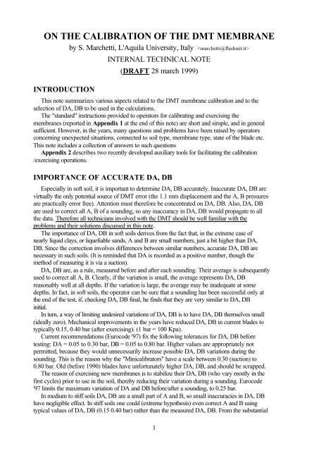
<strong>ON</strong> <strong>THE</strong> CALIBRATI<strong>ON</strong> <strong>OF</strong> <strong>THE</strong> <strong>DMT</strong> <strong>MEMBRANE</strong>by S. <strong>Marchetti</strong>, L'Aquila University, Italy INTRODUCTI<strong>ON</strong>INTERNAL TECHNICAL NOTE(DRAFT 28 march 1999)This note summarizes various aspects related to the <strong>DMT</strong> membrane calibration and to theselection of DA, DB to be used in the calculations.The "standard" instructions provided to operators for calibrating and exercising themembranes (reported in Appendix 1 at the end of this note) are short and simple, and in generalsufficient. However, in the years, many questions and problems have been raised by operatorsconcerning unexpected situations, connected to soil type, membrane type, state of the blade etc.This note includes a collection of answers to such questionsAppendix 2 describes two recently developed auxiliary tools for facilitating the calibration/exercising operations.IMPORTANCE <strong>OF</strong> ACCURATE DA, DBEspecially in soft soil, it is important to determine DA, DB accurately. Inaccurate DA, DB arevirtually the only potential source of <strong>DMT</strong> error (the 1.1 mm displacement and the A, B pressuresare practically error free). Attention must therefore be concentrated on DA, DB. Also, DA, DBare used to correct all A, B of a sounding, so any inaccuracy in DA, DB would propagate to allthe data. Therefore all technicians involved with the <strong>DMT</strong> should be well familiar with theproblems and their solutions discussed in this note.The importance of DA, DB in soft soils derives from the fact that, in the extreme case ofnearly liquid clays, or liquefiable sands, A and B are small numbers, just a bit higher than DA,DB. Since the correction involves differences between similar numbers, accurate DA, DB arenecessary in such soils. (It is reminded that DA is recorded as a positive number, though themethod of measuring it is via a suction).DA, DB are, as a rule, measured before and after each sounding. Their average is subsequentlyused to correct all A, B. Clearly, if the variation is small, the average represents DA, DBreasonably well at all depths. If the variation is large, the average may be inadequate at somedepths. In fact, in soft soils, the operator can be sure that a sounding has been successful only atthe end of the test, if, checking DA, DB final, he finds that they are very similar to DA, DBinitial.In turn, a way of limiting undesired variations of DA, DB is to have DA, DB themselves small(ideally zero). Mechanical improvements in the years have reduced DA, DB in current blades totypically 0.15, 0.40 bar (after exercising). (1 bar = 100 Kpa).Current recommendations (Eurocode '97) fix the following tolerances for DA, DB beforetesting: DA = 0.05 to 0.30 bar, DB = 0.05 to 0.80 bar. Higher values are appropriately notpermitted, because they would unnecessarily increase possible DA, DB variations during thesounding. This is the reason why the "Minicalibrators" have a scale between 0.30 (suction) to0.80 bar. Old (before 1990) blades have unfortunately higher DA, DB, and should be scrapped.The reason of exercising new membranes is to stabilize their DA, DB (who vary mostly in thefirst cycles) prior to use in the soil, thereby reducing their variation during a sounding. Eurocode'97 limits the maximum variation of DA and DB before/after a sounding, to 0.25 bar.In medium to stiff soils DA, DB are a small part of A and B, so small inaccuracies in DA, DBhave negligible effect. In stiff soils one could (extreme hypothesis) even correct A and B usingtypical values of DA, DB (0.15 0.40 bar) rather than the measured DA, DB. From the substantial1
viewpoint the Eurocode '97 prescriptions for DA, DB are too severe for a stiff soil, because theresults would be correct anyway for all practical purposes. However using laxer tolerances is notadvisable because it would induce the operator to a bad habit.NOTE : The "membrane calibration" is not, strictly speaking, a calibration, since the termcalibration is usually related to the scale of a measuring instrument. The membrane, instead, is apassive separator gas/soil and not a measuring instrument. Actually the membrane is a "tare" andthe "calibration" is in reality a "tare determination". Such distinction will be ignored below.SELECTING <strong>THE</strong> "AVERAGE" DA, DB TO BE USED IN <strong>THE</strong>CALCULATI<strong>ON</strong>SSelecting the average DA, DB is a step deserving the attention of the engineer. As a minimum,while performing the average, he will get a feeling of the entity of DA, DB and their variationsduring the sounding (a broad measure of the care exercised during the execution).If the test has been regular (e.g. the membrane has not been overinflated, and the Eurocode '97limits for DA, DB and their variations have not been exceeded), as it happens in most cases, thebefore/after values of DA, DB are very close, so that their arithmetic average is perfectlyadequate (even though, if some rounding has to be done, it is advisable to choose the average onthe low side. E.g. assume 0.14 as the average between 0.16 and 0.13).The case of wider DA, DB variations is considered in a next paragraph.INFLUENCE <strong>OF</strong> UNCERTAINTIES <strong>OF</strong> DA, DB <strong>ON</strong> <strong>THE</strong> INTERPRETEDRESULTSFor the following considerations, the equations for interpreting Cu and Ed can beapproximated as :Cu = p o / 9Ed = 34.7 [(B-A) - (DA+DB)]Typical variations of DA during a sounding : from a few KPa to 20 KPa (20 KPa is anunusually high variation). Note that even such 20 KPa variation (corresponding to an uncertainty= distance from average = 10) would translate into an uncertainty in Cu of nearly 1 KPa, a verysmall quantity.Typical variations of (DA+DB) during a sounding : from a few KPa to 30 KPa (30 KPa is anunusually high variation). Note that even such 30 KPa variation (uncertainty = 15) wouldtranslate into an uncertainty in Ed of nearly 5 bar, a quite small quantity.In conclusion the resolution, even for unusually high DA, DB variations, are 1 KPa for Cu, 5bar for Ed (or M). A more typical resolution is 0.5 KPa for Cu and 3 bar for Ed (or M). (All theabove resolution figures should be intended preceded by the ± sign).It may be noted that Cu is much less vulnerable than the moduli to uncertainties in DA, DB.Cu is derived essentially by A, and, as noted, uncertainties in DA very rarely translate intouncertainties in Cu higher than 1 Kpa. Hence even in situations of "bad DA, DB", Cu from <strong>DMT</strong>is instrumentally highly dependable.SELECTING <strong>THE</strong> "AVERAGE" DA, DB IN CASE <strong>OF</strong> WIDEVARIATI<strong>ON</strong>SIf DA or DB vary more than 0.25 bar during a sounding, the results, according to Eurocode '97prescriptions, should be discarded and the sounding repeated. This is an appropriate clause for astandard. However, in many cases, the results can be salvaged, obtaining quite reasonable results,provided DA, DB are chosen with care. Unfortunately then, selecting DA, DB becomessubjective, which in general is undesirable and should be avoided.2
For any useful purpose, this section offers guidance to perform judiciously such subjectiveDA, DB choice.If the soil is stiff, the results are not much affected by DA, DB. Therefore, if using thearithmetic average of DA, DB, leads to a minimum value of Ed in the entire sounding say ≥ 25bar, then DA, DB can be confirmed.If the soil is soft, inaccurate or excessive DA, DB variations may give rise to severalcontradictions. A frequent contradiction, for instance, is the presence of many negative Ed(physically impossible). Such negative Ed will be noted by the operator when, after havingentered the data in the computer, he prints the intermediate output, containing the input data andthe Ed. In principle, in presence of several negative Ed, the results should be discarded. As analternative, as mentioned, in many cases the data can still be salvaged by modifying judiciouslyDA, DB. In choosing the "adequate average" DA, DB, the following suggestions may be useful :1. Verify if the negative Ed are only a few or many. In the first case check if A, B, at thedepths of the negative Ed, were entered correctly. In case of suspect A,B enter 0,0(interpreted by the computer as missing A,B at that depth).2. If the Ed negative are many, (hence isolated typing errors are not the cause), all Ed can belifted by reducing DA, DB. While reducing DA,DB keep in mind the following:• Typical average values of DA, DB are 0.15, 0.40.• Very seldom DA is outside the range 0.07-0.23 bar. Very often values of DA in thevicinity of 0.20 are directly reduced to 0.15 or 0.10.• Decrease DA, DB in a balanced (proportional) manner.• Keep reducing DA, DB until all Ed values are non-negative (or maybe 4-7 bar), byconsulting each time the intermediate output.3. In general, a "logical" average is better than the "arithmetic" average. For instance, in caseof a combination of a soft layer and a hard layer, choose DA, DB closer to DA, DB thatpresumably were in effect in the soft layer, mostly in need of adequate DA, DB.Another contradiction (the expert operator can use it to recognize a situation of bad DA, DB)is represented by pairs of A, B whose difference B-A is smaller than DA+DB (all positivenumbers). E.g. if DA=0.15 and DB=0.40, B-A should not be less than 0.55. In fact the modulusEd is proportional to the difference (B-A) - (DA+DB). Since DA, DB are nothing less than A andB in free air, the distance B-A, when the blade is in the soil, can only increase, but not decrease(negative modulus physically impossible). The same condition is expressed, in mathematicalform, by the equation reported above for Ed. Hence B-A smaller than DA+DB signals some erroreither in A, B or in DA, DB. On the other hand, in water, or even in liquid mud, both B and Awould increase with depth, but the difference would remain 0.55.CASES WHEN DA, DB <strong>OF</strong> A NEW <strong>MEMBRANE</strong> ARE (RARELY)OUTSIDE TOLERANCEWhen a new membrane is mounted on a current (after 1990) blade, DA, DB are, as a rule,within tolerance (even before exercising), i.e. DA0.80, the likely reason is that the bladeis older than 1990. These blades are obsolete and should be scrapped. (Another good reason toscrap the old blades is that they were made of mild stainless steel, very vulnerable to damage andbending). Anyway even DA, DB of an old blade can be reduced within tolerance by the expedientof interposing an additional 0.15 gasket on top of the basic gasket.Even in recent blades it has been found, exceptionally (when the geometrical tolerancescombine most unfavorably), DA>0.30 or DB>0.80. In this case the remedy is to use a slightly3
thicker neoprene gasket (say 0.97 mm rather than the usual 0.90 mm) or to add an additional 0.15mm gasket on top of the basic gasket. This will reduce DA, DB within tolerance.HOW DA, DB CAN GO OUT <strong>OF</strong> TOLERANCE AND HOW TO AVOID ITIn practice the only mechanism by which DA, DB can go out of tolerance is overinflation ofthe membrane (far) beyond the B position. Once overinflated, a membrane requires excessivesuction to close (DA generally >0.30 bar), and even DB may be a suction.It is possible that the soil, by pushing repeatedly against an overinflated membrane, will sendit back below B. But then DA, DB final will differ considerably, in general, from the initialvalues.For accuracy and productivity it is convenient to avoid the two causes of membrane overinflation.The first cause is a trivial one, i.e. omitting deflation after the B-signal. This may happen to aninexperienced operator, but he will learn quickly.A more serious reason can be the absence of the B-signal (an electrical malfunctioning). Thisinconvenience is discussed in the next section.ABSENCE <strong>OF</strong> <strong>THE</strong> B-SIGNALSuch absence is due to the lack of contact at the B-position, in turn due to dirt/ grains/ tissue atthe points of electrical contact, namely below the sensing disk or at the bases of the small steelcylinders (see arrows in the figure below).If the absence of B starts suddenly in the middle of a sounding, the operator has no way ofbeing aware of this inconvenience, and finds himself in a puzzling situation, since he does notknow if the high pressure he is reaching is due to anunexpectedly stronger layer or to the absence of B-signal. Insuch cases a prudent step may be to deflate and take a secondchance by advancing the tip 10 cm, rather than the usual 20cm, and repeating A, B. (Then the operator must advance thetip only 10 cm to recoup the right sequence).The obvious remedy to the absence of the B-signal is tokeep well clean the electrical contact points, blowing each ofthe involved pieces with compressed air. There is no need todo the cleaning periodically, but only after a damageallowing dirt inside the blade.A recommended check (before starting a sounding) useful for reducing the risk of absence ofB reading during a sounding, is the following. At the beginning of the test (i.e. at calibration),push-pull the syringe i.e. repeat DA, DB 10 or 20 times, to make sure that the A-signal and B-signal are sharp.Another rare cause of absence of B-signal may be the lack of contact between the sensing diskand its seating, i.e. the disk not reaching the bottom of the seating. This, in turn, may be due toinadequate gripping force of the pvc lining on the sensing disk. The correct gripping shouldcorrespond to an extraction force of the sensing disk of at least 2 or 3 Kg. If the couplingbecomes loose (disk too free to move) then the gripping force should be re-increased. One quickfix can be the addition, while reinstalling the disk, of a small piece of plastic sheet laterally (NOTon the bottom).TYPES <strong>OF</strong> <strong>MEMBRANE</strong>S AVAILABLEThis information updates previous information contained in various manuals or papers.Since 1990 one type of membrane is by far the mostly frequently used. This type is the "highstrength" (or "hard") membrane 0.20 mm thick.4
Such choice is a consequence of the improvements introduced in all blades after 1990 in theshape of the "hub" receiving the membranes. Such improvements have led to DA, DB, with hardmembranes, lower than old blades with soft membranes. Thus the combination "new blade + hardmembranes" has low DA, DB, and, at the same time, substantially increased damage resistance.Therefore the old soft membranes, though still available, are rarely used.Another valid type of membrane is also available. The material is the same as the "highstrength" membranes, but the thickness is 0.25 mm, further increasing damage resistance.Fortunately DA, DB of the 0.25 membranes are only 15-20% higher than for the 0.20 mmmembranes, i.e. their typical DA, DB are say 0.18, 0.55. Hence their possible variation during asounding is larger by a similar percentage. Thus the typical resolution for the 0.25 mmmembranes may be 0.8 KPa for Cu and 5 bar for Ed (or M). Since the difference in resolution(0.8 vs 0.5 Kpa for Cu and 5 vs 3 bar for Ed) is quite small, then the 0.25 mm thickness may bepreferable when testing in soils that may cut the membrane.NOTE : In order to distinguish soft/hard membranes, examine the outer rim. If the rim isperfectly flat, the membranes are soft. If the rim has "waves", the membranes are hard.HOW TO HANDLE <strong>THE</strong> ZERO <strong>OF</strong>FSET <strong>OF</strong> <strong>THE</strong> GAGE (Zm)Ideally, the zero offset of the pressure gage (Zm = reading of the gage of the front panel of<strong>DMT</strong> when the vent valve is open) should be zero (in most <strong>DMT</strong> pressure gages Zm can beregulated and set to zero). However small deviations, properly considered, are ininfluent onaccuracy.The rest of this paragraph will consider the general case of a gage having a non-zero Zm.In order to handle Zm correctly, it is necessary to recognize first which one of the following 2cases applies :• Case 1 : the same gage is used for reading DA,DB and all subsequent A and B• Case 2 : DA, DB are determined using a separate accurate vacuomanometer (withtypically its zero offset =0). Then all A, B are read by means of the gage of the<strong>DMT</strong>.Since the introduction of the dual gage front panel (approximately 1990), Case 1 is by far themost common, since the low scale gage permits to read DA, DB with fair accuracy.In Case 1 Zm should be recorded as zero even if Zm is not zero. In fact not only all A, B, butalso DA, DB are affected by Zm, so that the Zm correction is already accounted for in DA, DB(this compensation can be derived readily from the algebra of the correction formulae for A andB). In conclusion today's operators have to write "zero" for Zm in the field form. If the operatorprefers, for correctness of documentation, he can write the real Zm. But in any case later in thecomputer Zm must be entered as Zm=0 (entering the real Zm would result in applying twice thecorrection to A and B).By contrast, in Case 2 (the today unusual case when the old single-gage panel is used) the Zmthat operators have to write in the field form is the real Zm of the front panel gage. Similarly, theZm to be entered later in the computer must be the real Zm. This because originally the formulaewere developed assuming that DA, DB were exact (being measured by a separate accuratevacuomanometer), and only A and B needed the correction.BIBLIOGRAPHYDetails on membrane calibration and selection of DA,DB can also be found in the following tworeferences, though, of course, many changes since have been updated in this document.<strong>Marchetti</strong>, S. & Crapps, D.K. 1981. Flat Dilatometer Manual. Internal Report of G.P.E. Inc. (in particular p.4.1)Schmertmann, J.H.1988. Guidelines for Using the CPT, CPTU and <strong>Marchetti</strong> <strong>DMT</strong> for Geotechnical Design. U.S.Dept. of Transportation, Federal Highway Administration, Office of Research and Special Studies. Report No.FHWA-PA-87-024+84-24, Vol. 3-4.(In particular Vol. 3 - <strong>DMT</strong> Test Methods And Data Reduction pp. 2.16-2.22)5
APPENDIX 1"STANDARD" OPERATOR's INSTRUCTI<strong>ON</strong>S C<strong>ON</strong>CERNING :<strong>MEMBRANE</strong> CALIBRATI<strong>ON</strong> AND EXERCISING PROCEDURECALIBRATI<strong>ON</strong>The membrane calibration (determining DA, DB) can be performed in two configurations :1. The first configuration (blade accessible) is adopted for example at the beginning of asounding, when the blade is still in the hands of the operator. The operator will then use theshort calibration cable, or the short calibration connector (attached to a clamp on the carryingcase).2. The second configuration (blade not readily accessible) is used when the blade is under thepenetrometer, and is connected to the control box with cables of normal length (say 20 to 30m).Calibration using the short calibration connector (blade accessible)Insert the syringe quickconnector into the socket "syringe" in the front panelDetach the "short calibration connector" from the clamp in the carrying case and :(a) Attach one end to the blade to be calibrated"(b) Plug the quickconnector into the socket "dilatometer" in the front panel.(c) Connect the electrical jack to the socket "ground" in the front panelSet piston of the syringe approximately half way (when in need of sucking or expel surplus air,open/ then close the fast-vent-valve).Pull back (almost fully) the piston of the syringe, then slowly release it and read DA.Push slowly the piston of the syringe and read DB. (If necessary to charge/discharge the syringe,open/ then close the fast-vent-valve).Repeat the DA, DB determination a few times to be sure, then write their values.Calibration with the blade under the penetrometer (blade not readily accessible).The connections are the same as during current testing. Thus the blade is connected to thecontrol box by a tubing say 20 or 30 m long, while the ground cable connects the control box tothe rods.Set piston of the syringe approximately half way and proceed as indicated in the previousconfiguration. The only difference is that, due to the length of the <strong>DMT</strong> tubings, the response ofthe pressure gages to the syringe is not immediate (there is some time lag). Therefore, in thatconfiguration, DA, DB must be taken slowly.NOTESDuring calibration, the valve "general" should be closed, to avoid communication with the highpressureportion of the circuit. Better still, the gas tank should be disconnected and the entirehigh-pressure portion vented. As an additional precaution, close also the micrometer valve, notneeded for the calibration.Generally DA, DB of a blade are checked in the office (e.g. by the Minicalibrator) and written ona sticker on the blade. Once in the field, there could be small differences between DA and DB onthe sticker and DA, DB taken before testing. The DA, DB to consider are those taken, just beforetesting, with the same control box used to take all the A, B readings.6
EXERCISING PROCEDUREAfter having mounted a new membrane, the membrane needs to be "exercised" in order tostabilize DA, DB. The exercising operation simply consists in pressurizing the blade in free airat 4-5 bar. This pressurization can be performed in the same configuration as when testing, or,more conveniently, using an auxiliary tool, the "exercise syringe", permitting to performhandily the exercising operation, without need to use the gas tank, the control box and atubing.The "exercise syringe" is directly screwed (as a screwdriver) on the rear of the blade. Note thatthe syringe has a START mark and an END mark. Before connecting the syringe to theblade, the piston should be at the START position, then the syringe can be screwed to theblade.When pushing the piston of the syringe from START to END , the air pressure will reach 4 to 5bar, which is the pressure needed for the exercising (the force is approximately 25 Kg, or 250Newton).The exercising pressure can be applied only once, or, equally well, 2 or 3 times.If the exercising is performed with the blade vertical submerged in a bucket of water, it ispossible to verify blade airtightness.After exercising, insure that DA, DB are in tolerance : DA=0.05 to 0.30 (typically 0.15), DB=0.05 to 0.80 bar (typically 0.40).Connections during calibration in case the blade is easily accessible7
APPENDIX 2TWO AUXILIARY TOOLS FOR FACILITATING <strong>THE</strong> CALIBRATI<strong>ON</strong>AND <strong>THE</strong> EXERCISING OPERATI<strong>ON</strong>S :<strong>THE</strong> MINICALIBRATOR AND <strong>THE</strong> EXERCISE SYRINGE<strong>THE</strong> MINICALIBRATORThe Minicalibrator is an auxiliary tool permitting to perform handily the calibration of amembrane (determine DA, DB) and to verify the proper functioning of a blade (regular on/offswitching of the signal), without need of deploying the regular control box.Characteristics of the Minicalibrator:• It is small (20 cm long) and light (200 grams), and is able by itself (without control box,cables, ground cable) to check DA, DB of a blade.• It is equipped with a pressure gage that is small, but has a scale spanning the full tolerancerange (-30 to 80 KPa), and therefore is very accurate.• It is equipped with a small buzzer and a battery that will last for years. Uses one 1/2 AA 3Vbattery, terminating with wires (easily found in computer shops).• It is directly screwed (as a screwdriver) on the rear of the blade.It fulfills fast and conveniently the following tasks :• Check DA, DB after a blade has just been revised.• Check DA, DB and run a general functioning check of a blade in the office before moving to asite.• Check if DA, DB have reached regular values after installing / exercising a new membrane.• Check handily in a hotel room, after a day of field work, if the blades are working properly. IfDA, DB are outside the green scale of the gage, the membrane has to be replaced. (Note thatblades older than 1990 may have DA, DB too high. Anyway DA, DB of a new membrane inan old blade can still be reduced within tolerance by interposing an additional 0.15 gasket ontop of the basic gasket).• Permits to field supervisors to verify quickly if the blades in use at the site are workingproperly and DA, DB are in tolerance"Cleanliness" checkThe Minicalibrator also permits to verify if the inside of the blade, below the sensing disk, is freefrom dirt or pieces of tissue or fabric. For this check, the operator applies 10 or 20 push-pullcycles and note if the signal inversions are sharp. If they are "hesitant", the operator shouldremove the membrane and clean or blow off dirt from the electrical contact points.NOTE• DA, DB of a real test, as a rule, must be taken - and written in the data sheet - just before (andafter) a sounding using the same control box used for performing the sounding. Hence DA,DB taken previously with the Minicalibrator have to be considered as indicative. Nevertheless,in most cases, the differences are very small.• Due to the lack of tubing, the response of the gage of the Minicalibrator to the pressuresapplied by the syringe is immediate. This immediate response should not induce the operatorto forget that, when he takes DA, DB with the usual 20 or 30 m <strong>DMT</strong> tubing, there is sometime lag, and therefore, in the configuration with real tubings, he must take DA, DB slowly.8
<strong>THE</strong> MINICALIBRATOR<strong>THE</strong> EXERCISE SYRINGEThe "exercise syringe" is an auxiliary tool permitting to perform handily the exercisingoperation, without need to use the gas tank, the control box and a tubing.The exercising operation is performed whenever a new membrane is mounted. The scope is tostabilize DA, DB. The operation consists in pressurizing the blade in free air at 4-5 bar.The "exercise syringe" is directly screwed (as a screwdriver) on the rear of the blade. Note thatthe syringe has a START mark and an END mark. Before connecting the syringe to theblade, the piston should be at the START position, then the syringe can be screwed to theblade.When pushing the piston of the syringe from START to END , the air pressure will reach 4 to 5bar, which is the pressure needed for the exercising (the force is approximately 25 Kg, or 250Newton).The exercising pressure can be applied only once, or, equally well, 2 or 3 times.If the exercising is performed with the blade vertical submerged in a bucket of water, it ispossible to verify blade airtightness.After exercising, insure that DA, DB are in tolerance : DA=0.05 to 0.30 (typically 0.15), DB=0.05 to 0.80 bar (typically 0.40).<strong>THE</strong> EXERCISE SYRINGE9


