(SDMT) in non-penetrable soils - Marchetti DMT
(SDMT) in non-penetrable soils - Marchetti DMT
(SDMT) in non-penetrable soils - Marchetti DMT

You also want an ePaper? Increase the reach of your titles
YUMPU automatically turns print PDFs into web optimized ePapers that Google loves.
V S measurements by seismic dilatometer (<strong>S<strong>DMT</strong></strong>) <strong>in</strong> <strong>non</strong>-<strong>penetrable</strong> <strong>soils</strong><br />
Mesures de V S par le dilatomètre sismique (<strong>S<strong>DMT</strong></strong>) dans sols <strong>non</strong> pénétrables<br />
G. Totani, P. Monaco, S. <strong>Marchetti</strong><br />
University of L'Aquila, Italy<br />
D. <strong>Marchetti</strong><br />
Studio Prof. <strong>Marchetti</strong>, Rome, Italy<br />
ABSTRACT<br />
This paper illustrates the procedure for obta<strong>in</strong><strong>in</strong>g measurements of the shear wave velocity V S by seismic dilatometer (<strong>S<strong>DMT</strong></strong>) <strong>in</strong><br />
backfilled boreholes <strong>in</strong> <strong>non</strong>-<strong>penetrable</strong> <strong>soils</strong>. The possibility of such measurement descends from the fact that the path of the shear<br />
wave from the surface to the upper and lower receiver <strong>in</strong>cludes a short path <strong>in</strong> the backfill of very similar length for both receivers.<br />
The <strong>S<strong>DMT</strong></strong> equipment/test procedure and the borehole backfill<strong>in</strong>g technique are briefly described. The validation of the method by<br />
comparison of parallel profiles of V S obta<strong>in</strong>ed <strong>in</strong> the "virg<strong>in</strong>" soil and <strong>in</strong> a backfilled borehole is presented. V S profiles obta<strong>in</strong>ed by<br />
<strong>S<strong>DMT</strong></strong> <strong>in</strong> backfilled boreholes at two test sites <strong>in</strong> central Italy, Sulmona (coarse gravel) and L'Aquila (calcareous breccia), are<br />
compared to V S profiles obta<strong>in</strong>ed by the traditional Down-Hole technique and related to the stratigraphic profiles of the subsoil.<br />
RÉSUMÉ<br />
Cet article décrit la procédure pour obtenir des mesures de la vitesse des ondes de cisaillement V S par le dilatomètre sismique (<strong>S<strong>DMT</strong></strong>)<br />
dans forages remblayés avec du sable dans sols <strong>non</strong> pénétrables. La possibilité d'une telle mesure descend du fait que le chem<strong>in</strong> de<br />
l'onde de cisaillement de la surface au récepteur supérieur et <strong>in</strong>férieur <strong>in</strong>clut un court chem<strong>in</strong> dans le remblai de longueur très<br />
semblable pour les deux récepteurs. L'équipement et la procédure de l'essai par <strong>S<strong>DMT</strong></strong> et la technique de remblayage du forage sont<br />
brièvement décrites. La validation de la méthode par la comparaison des profils parallèles de V S obtenu dans le sol "vierge" et dans un<br />
forage remblayé est présentée. Les profils de V S obtenus par <strong>S<strong>DMT</strong></strong> dans forages remblayés à deux sites d'essai en l'Italie centrale,<br />
Sulmona (gravier grossier) et L'Aquila (brèche calcaire), sont comparés à les profils de V S obtenus par la technique Down-Hole<br />
traditionnelle et mise en relation avec les profils stratigraphiques du sous-sol.<br />
Keywords : seismic dilatometer <strong>S<strong>DMT</strong></strong>, shear wave velocity V S , <strong>non</strong>-<strong>penetrable</strong> <strong>soils</strong><br />
1 INTRODUCTION<br />
The seismic dilatometer (<strong>S<strong>DMT</strong></strong>) is the comb<strong>in</strong>ation of the<br />
traditional "mechanical" Flat Dilatometer (<strong>DMT</strong>) <strong>in</strong>troduced by<br />
<strong>Marchetti</strong> (1980) with a seismic module placed above the <strong>DMT</strong><br />
blade. The <strong>S<strong>DMT</strong></strong> module is a probe provided with two<br />
receivers, spaced 0.5 m, for measur<strong>in</strong>g the shear wave velocity<br />
V S . From V S the small stra<strong>in</strong> shear modulus G 0 may be<br />
determ<strong>in</strong>ed us<strong>in</strong>g the theory of elasticity. The eng<strong>in</strong>eer<strong>in</strong>g<br />
application of such technique follows from different motivations:<br />
– V S and G 0 are at the base of any seismic analysis.<br />
– The G-γ decay curves of stiffness with stra<strong>in</strong> level are an<br />
<strong>in</strong>creas<strong>in</strong>gly requested <strong>in</strong>put <strong>in</strong> seismic analyses and, <strong>in</strong><br />
general, <strong>in</strong> <strong>non</strong> l<strong>in</strong>ear analyses.<br />
– Increas<strong>in</strong>g demand for liquefiability evaluations.<br />
– Seismic site classification us<strong>in</strong>g directly V S rather than the<br />
SPT blow count N SPT or the undra<strong>in</strong>ed shear strength s u (as<br />
required e.g. by the Eurocode 8 and by EC8-<strong>in</strong>spired<br />
national technical codes).<br />
– Availability of the usual <strong>DMT</strong> results (e.g. constra<strong>in</strong>ed<br />
modulus M <strong>DMT</strong> ) for common design applications (e.g.<br />
settlement predictions).<br />
The <strong>S<strong>DMT</strong></strong> equipment and test procedure are briefly<br />
described <strong>in</strong> the paper. Detailed <strong>in</strong>formation and comments on<br />
<strong>S<strong>DMT</strong></strong> results and applications can be found <strong>in</strong> previous papers,<br />
<strong>in</strong> particular <strong>in</strong> <strong>Marchetti</strong> et al. (2008). (Information on the<br />
mechanical <strong>DMT</strong> can be found <strong>in</strong> the comprehensive report by<br />
the ISSMGE Technical Committee TC16 2001).<br />
This paper is focused essentially on the procedure for<br />
obta<strong>in</strong><strong>in</strong>g profiles of V S by <strong>S<strong>DMT</strong></strong> <strong>in</strong> backfilled boreholes <strong>in</strong><br />
<strong>non</strong>-<strong>penetrable</strong> <strong>soils</strong>. In particular the paper presents the results<br />
of V S measurements obta<strong>in</strong>ed by <strong>S<strong>DMT</strong></strong> <strong>in</strong> backfilled boreholes<br />
at various test sites located <strong>in</strong> the old centres of the towns of<br />
Sulmona and L'Aquila, <strong>in</strong> a highly seismic region <strong>in</strong> central<br />
Italy. The subsoil at the <strong>in</strong>vestigated sites is predom<strong>in</strong>antly<br />
coarse gravel (Sulmona) and calcareous breccia (L'Aquila).<br />
<strong>S<strong>DMT</strong></strong> test<strong>in</strong>g was part of site <strong>in</strong>vestigation programs carried<br />
out to determ<strong>in</strong>e fundamental soil parameters required for<br />
seismic microzonation, prediction of the site seismic response<br />
and design of retrofitt<strong>in</strong>g of historic build<strong>in</strong>gs.<br />
2 THE SEISMIC DILATOMETER (<strong>S<strong>DMT</strong></strong>)<br />
The seismic dilatometer (<strong>S<strong>DMT</strong></strong>) is the comb<strong>in</strong>ation of the<br />
standard <strong>DMT</strong> equipment with a seismic module for measur<strong>in</strong>g<br />
the shear wave velocity V S . Initially conceived for research, the<br />
<strong>S<strong>DMT</strong></strong> is gradually enter<strong>in</strong>g <strong>in</strong>to use <strong>in</strong> current site <strong>in</strong>vestigation<br />
practice. The test is conceptually similar to the seismic cone<br />
(SCPT). First <strong>in</strong>troduced by Hepton (1988), the <strong>S<strong>DMT</strong></strong> was<br />
subsequently improved at Georgia Tech, Atlanta, USA (Mart<strong>in</strong><br />
& Mayne 1997, 1998, Mayne et al. 1999).<br />
A new <strong>S<strong>DMT</strong></strong> system (Fig. 1) has been recently developed <strong>in</strong><br />
Italy. The seismic module (Fig. 1a) is a cyl<strong>in</strong>drical element<br />
placed above the <strong>DMT</strong> blade, provided with two receivers<br />
spaced 0.5 m. The signal is amplified and digitized at depth.<br />
The true-<strong>in</strong>terval test configuration with two receivers avoids<br />
possible <strong>in</strong>accuracy <strong>in</strong> the determ<strong>in</strong>ation of the "zero time" at<br />
the hammer impact, sometimes observed <strong>in</strong> the pseudo-<strong>in</strong>terval<br />
one-receiver configuration. Moreover, the couple of<br />
seismograms recorded by the two receivers at a given test depth<br />
corresponds to the same hammer blow and not to different<br />
blows <strong>in</strong> sequence, which are not necessarily identical. Hence<br />
the repeatability of V S measurements is considerably improved
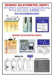
a) b) c) d)<br />
Figure 1. (a) <strong>DMT</strong> blade and seismic module. (b) Schematic layout of the seismic dilatometer test. (c) Seismic dilatometer equipment. (d) Shear wave<br />
source at the surface.<br />
seismograms – <strong>in</strong> particular the <strong>in</strong>itial waves – rather than be<strong>in</strong>g<br />
based on the first arrival time or specific marker po<strong>in</strong>ts <strong>in</strong> the<br />
seismogram. Figure 2 shows an example of seismograms<br />
obta<strong>in</strong>ed by <strong>S<strong>DMT</strong></strong> at various test depths at the site of Fuc<strong>in</strong>o (it<br />
is a good practice to plot side-by-side the seismograms as<br />
recorded and re-phased accord<strong>in</strong>g to the calculated delay).<br />
V S measurements by <strong>S<strong>DMT</strong></strong> have been validated by<br />
comparison with V S measurements obta<strong>in</strong>ed by other <strong>in</strong> situ<br />
seismic tests at various research sites. As an example Figure 3<br />
shows V S comparisons at the research site of Fuc<strong>in</strong>o, Italy (NC<br />
cemented clay), extensively <strong>in</strong>vestigated at the end of the '80s.<br />
The profile of V S obta<strong>in</strong>ed by <strong>S<strong>DMT</strong></strong> <strong>in</strong> 2004 (Fig. 3) is <strong>in</strong> quite<br />
good agreement with V S profiles obta<strong>in</strong>ed by SCPT, Cross-Hole<br />
and SASW <strong>in</strong> previous <strong>in</strong>vestigations (AGI 1991). Similar<br />
favourable comparisons are reported e.g. by Hepton (1988),<br />
McGillivray & Mayne (2004) and Młynarek et al. (2006).<br />
Figure 2. Example of seismograms obta<strong>in</strong>ed by <strong>S<strong>DMT</strong></strong> at the site of<br />
Fuc<strong>in</strong>o (Italy)<br />
SCPT<br />
Cross Hole<br />
SASW<br />
AGI (1991)<br />
<strong>S<strong>DMT</strong></strong><br />
(2004)<br />
Figure 3. Comparison of V S profiles obta<strong>in</strong>ed by <strong>S<strong>DMT</strong></strong> and by SCPT,<br />
Cross-Hole and SASW (AGI 1991) at the research site of Fuc<strong>in</strong>o (Italy)<br />
(observed V S repeatability ≈ 1-2 %). V S is obta<strong>in</strong>ed (Fig. 1b) as<br />
the ratio between the difference <strong>in</strong> distance between the source<br />
and the two receivers (S 2 - S 1 ) and the delay of the arrival of the<br />
impulse from the first to the second receiver (∆t). V S<br />
measurements are obta<strong>in</strong>ed every 0.5 m of depth. The shear<br />
wave source at the surface (Fig. 1d) is a pendulum hammer<br />
which hits horizontally a steel rectangular base pressed vertically<br />
aga<strong>in</strong>st the soil (by the weight of the truck) and oriented with its<br />
long axis parallel to the axis of the receivers, so that they can<br />
offer the highest sensitivity to the generated shear wave.<br />
The determ<strong>in</strong>ation of the delay from <strong>S<strong>DMT</strong></strong> seismograms,<br />
normally carried out us<strong>in</strong>g the cross-correlation algorithm, is<br />
generally well conditioned, be<strong>in</strong>g based on the two<br />
3 V S BY <strong>S<strong>DMT</strong></strong> IN NON-PENETRABLE SOILS<br />
In cases where the soil is too hard to penetrate (e.g. gravel), or<br />
even <strong>in</strong> rock, V S measurements can be obta<strong>in</strong>ed by <strong>S<strong>DMT</strong></strong>s<br />
carried out <strong>in</strong>side boreholes backfilled with sand (only V S – no<br />
<strong>DMT</strong> measurements). The possibility of such measurement<br />
descends from the fact that the path of the shear wave from the<br />
surface to the upper and lower receiver <strong>in</strong>cludes a short path <strong>in</strong><br />
the backfill of very similar length for both receivers.<br />
The procedure is the follow<strong>in</strong>g:<br />
(1) A borehole, cased or uncased, is drilled by use of a drill<br />
rig to the required test depth.<br />
(2) The borehole is then backfilled with clean coarse sand –<br />
f<strong>in</strong>e gravel (gra<strong>in</strong> size 1-2 to 4-5 mm, no f<strong>in</strong>es) by pour<strong>in</strong>g the<br />
sand from the top of the borehole. The fill<strong>in</strong>g operation is<br />
carried out for depth <strong>in</strong>tervals of maximum length equal to the<br />
length of a s<strong>in</strong>gle section of the cas<strong>in</strong>g (e.g. 1.5 m), ensur<strong>in</strong>g<br />
each time that the bottom of the cas<strong>in</strong>g is ma<strong>in</strong>ta<strong>in</strong>ed below the<br />
top of the fill<strong>in</strong>g. The volume of the poured sand and the level<br />
of the backfill <strong>in</strong>side the borehole are systematically measured.<br />
If necessary water is poured from the top of the borehole to<br />
facilitate s<strong>in</strong>k<strong>in</strong>g and densification of the sand (these operations<br />
m<strong>in</strong>imize the risk that voids <strong>in</strong> the backfill may later reduce the<br />
contact between the seismic probe and the soil, required for<br />
obta<strong>in</strong><strong>in</strong>g accurate measurements of V S ). After fill<strong>in</strong>g each 1.5<br />
m depth <strong>in</strong>terval the cas<strong>in</strong>g is lifted, avoid<strong>in</strong>g rotation. This<br />
sequence is repeated until the borehole is completely filled with<br />
sand.<br />
(3) The <strong>S<strong>DMT</strong></strong> is then <strong>in</strong>serted and advanced <strong>in</strong>to the<br />
backfilled borehole <strong>in</strong> the usual way, e.g. by use of a<br />
penetrometer rig (carefully positioned <strong>in</strong> correspondence of the<br />
borehole) and V S measurements are carried out every 0.5 m of<br />
depth. No <strong>DMT</strong> measurements – mean<strong>in</strong>gless <strong>in</strong> the backfill<br />
soil – are taken <strong>in</strong> this case.
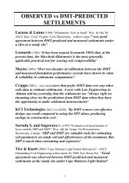
Vs (m /s)<br />
0 200 400 600 800<br />
0<br />
5<br />
10<br />
V S values expected for the soil types recognized <strong>in</strong> the borehole<br />
logs (Figs. 5 to 7).<br />
(b) The V S values by <strong>S<strong>DMT</strong></strong> are significantly dispersed <strong>in</strong><br />
gravel (≈ 400-800 m/s) and <strong>in</strong> the silty layers (≈ 400-600 m/s),<br />
more uniform <strong>in</strong> the deep stiff clay (≈ 500 m/s, Fig. 5). The<br />
"spikes" (high values of V S ) frequently observed <strong>in</strong> the V S<br />
profiles down to ≈ 30 m may possibly reflect a variable degree<br />
of cementation / composition / gra<strong>in</strong> size of the gravel.<br />
Z (m)<br />
15<br />
20<br />
25<br />
30<br />
<strong>S<strong>DMT</strong></strong> <strong>in</strong> the natural soil<br />
<strong>S<strong>DMT</strong></strong> <strong>in</strong> a drilled hole filled with sand<br />
35<br />
Figure 4. Comparison of V S profiles obta<strong>in</strong>ed by <strong>S<strong>DMT</strong></strong> <strong>in</strong> the natural<br />
soil and <strong>in</strong> a backfilled borehole at the site of Montescaglioso – G<strong>in</strong>osa<br />
(Matera), Italy<br />
Comparative tests at various sites <strong>in</strong>dicate that the values of<br />
V S obta<strong>in</strong>ed <strong>in</strong> a backfilled borehole are nearly co<strong>in</strong>cident with<br />
the V S obta<strong>in</strong>ed by penetrat<strong>in</strong>g the "virg<strong>in</strong>" soil. Figure 4 shows<br />
the comparison between the profiles of V S obta<strong>in</strong>ed, at the same<br />
site, by penetrat<strong>in</strong>g the "virg<strong>in</strong>" soil and <strong>in</strong> an adjacent borehole<br />
filled with sand. The good agreement observed between the two<br />
V S profiles (Fig. 4) supports the reliability of V S values obta<strong>in</strong>ed<br />
by this procedure.<br />
4 V S MEASUREMENTS BY <strong>S<strong>DMT</strong></strong> IN BACKFILLED<br />
BOREHOLES AT VARIOUS TEST SITES<br />
4.1 Sulmona site<br />
<strong>S<strong>DMT</strong></strong> tests at Sulmona were carried out <strong>in</strong> December 2006 –<br />
January 2007, <strong>in</strong> comb<strong>in</strong>ation with other seismic tests (Down-<br />
Hole, microtremor measurements). The site <strong>in</strong>vestigation<br />
program was part of a research project aimed at the second level<br />
seismic microzonation of the town of Sulmona, funded by<br />
Regione Abruzzo <strong>in</strong> cooperation with the Comune di Sulmona<br />
and <strong>in</strong>volv<strong>in</strong>g researchers of the University of L'Aquila, the<br />
University of Rome "La Sapienza" (Dipartimento Scienze della<br />
Terra) and the Dipartimento della Protezione Civile – Servizio<br />
Sismico Nazionale (see research report by Totani et al. 2007).<br />
The subsoil <strong>in</strong> the old town centre of Sulmona is generally<br />
constituted by an upper layer of calcareous medium to coarse<br />
well-graded gravel <strong>in</strong> sandy matrix, <strong>in</strong>clud<strong>in</strong>g layers of sandy<br />
and clayey silts. The gravel extends to a depth of ≈ 20-30 m<br />
below the ground surface and overlays a stiff clay layer,<br />
followed by dense sand below ≈ 57-60 m. The groundwater<br />
level is found at ≈ 19 to 25 m depth.<br />
Due to the predom<strong>in</strong>ance of "<strong>non</strong>-<strong>penetrable</strong>" coarse gravel<br />
<strong>in</strong> the upper 20-30 m, V S measurements by <strong>S<strong>DMT</strong></strong> were carried<br />
out <strong>in</strong> boreholes filled with sand accord<strong>in</strong>g to the above outl<strong>in</strong>ed<br />
procedure. Three boreholes were executed at different locations<br />
<strong>in</strong> the old town centre of Sulmona: Villa Comunale (30 m<br />
depth), Scuola Masciangioli (30 m) and Largo Tommasi (60 m).<br />
Figure 5 shows the profile of V S obta<strong>in</strong>ed by <strong>S<strong>DMT</strong></strong> down to a<br />
depth of 60 m <strong>in</strong> the backfilled borehole S3 (Largo Tommasi).<br />
The stratigraphic profile of the subsoil is shown alongside.<br />
Figures 6 and 7 show the profiles of V S obta<strong>in</strong>ed by <strong>S<strong>DMT</strong></strong><br />
down to 30 m <strong>in</strong> the backfilled boreholes S1 (Villa Comunale)<br />
and S2 (Scuola Masciangioli), the stratigraphic profiles of the<br />
subsoil and the profiles of V S obta<strong>in</strong>ed by Down-Hole tests<br />
carried out <strong>in</strong> adjacent boreholes (≈ 2 m distance) by researchers<br />
of the University of Rome "La Sapienza". Comments:<br />
(a) The values of V S obta<strong>in</strong>ed by <strong>S<strong>DMT</strong></strong> are <strong>in</strong> keep<strong>in</strong>g with<br />
Figure 5. Sulmona (Largo Tommasi) – Profile of V S obta<strong>in</strong>ed by <strong>S<strong>DMT</strong></strong><br />
<strong>in</strong> backfilled borehole and stratigraphic profile<br />
Figure 6. Sulmona (Villa Comunale) – Profiles of V S by <strong>S<strong>DMT</strong></strong> <strong>in</strong><br />
backfilled borehole, V S by Down-Hole and stratigraphic profile
L'Aquila – Piazza del Teatro. Also <strong>in</strong> this case the values of V S<br />
obta<strong>in</strong>ed by <strong>S<strong>DMT</strong></strong> are <strong>in</strong> keep<strong>in</strong>g with V S values expected for<br />
the soil types recognized <strong>in</strong> the borehole log. The values of V S<br />
<strong>in</strong> the breccia are very high (≈ 600-1000 m/s) and <strong>in</strong>crease with<br />
depth. The dispersion of the V S values possibly reflects the<br />
variability <strong>in</strong> soil properties due to the variability <strong>in</strong> sandy or<br />
silty-sandy matrix and cementation typical of this material.<br />
5 CONCLUSIONS<br />
Figure 7. Sulmona (Scuola Masciangioli) – Profiles of V S by <strong>S<strong>DMT</strong></strong> <strong>in</strong><br />
backfilled borehole, V S by Down-Hole and stratigraphic profile<br />
The results presented <strong>in</strong> this paper <strong>in</strong>dicate that the seismic<br />
dilatometer (<strong>S<strong>DMT</strong></strong>) can be advantageously used for obta<strong>in</strong><strong>in</strong>g<br />
measurements of V S (and of the small stra<strong>in</strong> shear modulus G 0<br />
determ<strong>in</strong>ed from V S ) <strong>in</strong> backfilled boreholes <strong>in</strong> <strong>non</strong>-<strong>penetrable</strong><br />
<strong>soils</strong>, commonly encountered <strong>in</strong> many seismic areas, e.g. <strong>in</strong> the<br />
Apenn<strong>in</strong>es regions <strong>in</strong> Italy. The possibility of such measurement<br />
descends from the fact that the path of the shear wave from the<br />
surface to the upper and lower receiver <strong>in</strong>cludes a short path <strong>in</strong><br />
the backfill of very similar length for both receivers.<br />
Comparisons at various sites, presented <strong>in</strong> this paper,<br />
<strong>in</strong>dicate that the true-<strong>in</strong>terval V S measurements obta<strong>in</strong>ed by<br />
<strong>S<strong>DMT</strong></strong> <strong>in</strong> backfilled boreholes, typically every 0.5 m of depth,<br />
provide more detailed and realistic profiles of V S compared to<br />
traditional techniques (e.g. pseudo-<strong>in</strong>terval Down-Hole<br />
method). Hence the <strong>S<strong>DMT</strong></strong> could be an alternative/<strong>in</strong>tegration<br />
to commonly used techniques to obta<strong>in</strong> reliable and detailed V S<br />
profiles <strong>in</strong> hard <strong>soils</strong>/soft rocks.<br />
ACKNOWLEDGMENTS<br />
<strong>S<strong>DMT</strong></strong> <strong>in</strong>vestigations at Sulmona and L'Aquila were funded by<br />
Regione Abruzzo.<br />
REFERENCES<br />
Figure 8. L'Aquila (Piazza del Teatro) – Profile of V S obta<strong>in</strong>ed by<br />
<strong>S<strong>DMT</strong></strong> <strong>in</strong> backfilled borehole and stratigraphic profile<br />
(c) The values of V S obta<strong>in</strong>ed by <strong>S<strong>DMT</strong></strong> are substantially <strong>in</strong><br />
agreement with the V S obta<strong>in</strong>ed by Down-Hole (Figs. 6 and 7).<br />
However the true-<strong>in</strong>terval V S measurements obta<strong>in</strong>ed by <strong>S<strong>DMT</strong></strong><br />
every 0.5 m of depth (every 0.25 m <strong>in</strong> the borehole S2, Fig. 7)<br />
provide more detailed and realistic profiles of V S compared to<br />
the pseudo-<strong>in</strong>terval Down-Hole technique (V S measurements<br />
every 1 m), which <strong>in</strong> this case had produced constant values of<br />
V S over several metres of depth.<br />
4.2 L'Aquila site<br />
One <strong>S<strong>DMT</strong></strong> test <strong>in</strong> a backfilled borehole to 30 m depth was<br />
carried out <strong>in</strong> the old town centre of L'Aquila (Piazza del<br />
Teatro) <strong>in</strong> April 2008. The subsoil <strong>in</strong> this area is generally<br />
constituted by an upper thick layer of calcareous breccia (f<strong>in</strong>e to<br />
coarse calcareous fragments generally <strong>in</strong> sandy or silty-sandy<br />
matrix). At the test site of Piazza del Teatro the breccia extends<br />
to a depth of ≈ 28 m below the ground surface, where marly<br />
limestone is encountered. The mechanical properties of the<br />
calcareous breccia are known to be highly variable, mostly<br />
depend<strong>in</strong>g on the variable degree of cementation.<br />
Figure 8 shows the profile of V S obta<strong>in</strong>ed by <strong>S<strong>DMT</strong></strong> (every<br />
0.25 m of depth) and the stratigraphic profile of the subsoil at<br />
AGI. 1991. Geotechnical Characterization of Fuc<strong>in</strong>o Clay. Proc. X<br />
ECSMFE, Firenze, 1: 27-40.<br />
Hepton, P. 1988. Shear wave velocity measurements dur<strong>in</strong>g penetration<br />
test<strong>in</strong>g. Proc. Penetration Test<strong>in</strong>g <strong>in</strong> the UK: 275-278. ICE.<br />
<strong>Marchetti</strong>, S. 1980. In Situ Tests by Flat Dilatometer. J. Geotech.<br />
Engrg. Div., 106(GT3): 299-321. ASCE.<br />
<strong>Marchetti</strong>, S., Monaco, P., Totani, G. & <strong>Marchetti</strong>, D. 2008. In Situ<br />
Tests by Seismic Dilatometer (<strong>S<strong>DMT</strong></strong>). In J.E. Laier, D.K. Crapps<br />
& M.H. Husse<strong>in</strong> (eds), From Research to Practice <strong>in</strong> Geotechnical<br />
Eng<strong>in</strong>eer<strong>in</strong>g, ASCE Geotech. Spec. Publ. No. 180: 292-311.<br />
Mart<strong>in</strong>, G.K. & Mayne, P.W. 1997. Seismic Flat Dilatometer Tests <strong>in</strong><br />
Connecticut Valley Varved Clay. ASTM Geotech. Test<strong>in</strong>g J., 20(3):<br />
357-361.<br />
Mart<strong>in</strong>, G.K. & Mayne, P.W. 1998. Seismic flat dilatometer <strong>in</strong><br />
Piedmont residual <strong>soils</strong>. Proc. 1 st Int. Conf. on Site<br />
Characterization, Atlanta, 2: 837-843. Rotterdam: Balkema.<br />
Mayne, P.W., Schneider, J.A. & Mart<strong>in</strong>, G.K. 1999. Small- and largestra<strong>in</strong><br />
soil properties from seismic flat dilatometer tests. Proc. 2 nd<br />
Int. Symp. on Pre-Failure Deformation Characteristics of<br />
Geomaterials, Tor<strong>in</strong>o, 1: 419-427.<br />
McGillivray, A. & Mayne, P.W. 2004. Seismic piezocone and seismic<br />
flat dilatometer tests at Treporti. Proc. 2 nd Int. Conf. on Site<br />
Characterization, Porto, 2: 1695-1700. Rotterdam: Millpress.<br />
Młynarek, Z., Gogolik, S. & <strong>Marchetti</strong>, D. 2006. Suitability of the<br />
<strong>S<strong>DMT</strong></strong> method to assess geotechnical parameters of post-flotation<br />
sediments. In R.A. Failmezger & J.B. Anderson (eds), Proc. 2 nd Int.<br />
Conf. on the Flat Dilatometer, Wash<strong>in</strong>gton D.C.: 148-153.<br />
TC16. 2001. The Flat Dilatometer Test (<strong>DMT</strong>) <strong>in</strong> Soil Investigations -<br />
A Report by the ISSMGE Committee TC16. May 2001, 41 pp.<br />
Repr<strong>in</strong>ted <strong>in</strong> R.A. Failmezger & J.B. Anderson (eds), Proc. 2 nd Int.<br />
Conf. on the Flat Dilatometer, Wash<strong>in</strong>gton D.C.: 7-48.<br />
Totani, G. (coord<strong>in</strong>ator University of L'Aquila – DISAT), Scarascia<br />
Mugnozza, G. (University of Rome "La Sapienza" – DST) & Naso,<br />
G. (Dipartimento Protezione Civile – Servizio Sismico Nazionale).<br />
(2007). Second level seismic microzonation of the town of<br />
Sulmona. F<strong>in</strong>al Research Report to Regione Abruzzo (<strong>in</strong> Italian).