(SDMT) in non-penetrable soils - Marchetti DMT
(SDMT) in non-penetrable soils - Marchetti DMT
(SDMT) in non-penetrable soils - Marchetti DMT

You also want an ePaper? Increase the reach of your titles
YUMPU automatically turns print PDFs into web optimized ePapers that Google loves.
a) b) c) d)<br />
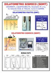
Figure 1. (a) <strong>DMT</strong> blade and seismic module. (b) Schematic layout of the seismic dilatometer test. (c) Seismic dilatometer equipment. (d) Shear wave<br />
source at the surface.<br />
seismograms – <strong>in</strong> particular the <strong>in</strong>itial waves – rather than be<strong>in</strong>g<br />
based on the first arrival time or specific marker po<strong>in</strong>ts <strong>in</strong> the<br />
seismogram. Figure 2 shows an example of seismograms<br />
obta<strong>in</strong>ed by <strong>S<strong>DMT</strong></strong> at various test depths at the site of Fuc<strong>in</strong>o (it<br />
is a good practice to plot side-by-side the seismograms as<br />
recorded and re-phased accord<strong>in</strong>g to the calculated delay).<br />
V S measurements by <strong>S<strong>DMT</strong></strong> have been validated by<br />
comparison with V S measurements obta<strong>in</strong>ed by other <strong>in</strong> situ<br />
seismic tests at various research sites. As an example Figure 3<br />
shows V S comparisons at the research site of Fuc<strong>in</strong>o, Italy (NC<br />
cemented clay), extensively <strong>in</strong>vestigated at the end of the '80s.<br />
The profile of V S obta<strong>in</strong>ed by <strong>S<strong>DMT</strong></strong> <strong>in</strong> 2004 (Fig. 3) is <strong>in</strong> quite<br />
good agreement with V S profiles obta<strong>in</strong>ed by SCPT, Cross-Hole<br />
and SASW <strong>in</strong> previous <strong>in</strong>vestigations (AGI 1991). Similar<br />
favourable comparisons are reported e.g. by Hepton (1988),<br />
McGillivray & Mayne (2004) and Młynarek et al. (2006).<br />
Figure 2. Example of seismograms obta<strong>in</strong>ed by <strong>S<strong>DMT</strong></strong> at the site of<br />
Fuc<strong>in</strong>o (Italy)<br />
SCPT<br />
Cross Hole<br />
SASW<br />
AGI (1991)<br />
<strong>S<strong>DMT</strong></strong><br />
(2004)<br />
Figure 3. Comparison of V S profiles obta<strong>in</strong>ed by <strong>S<strong>DMT</strong></strong> and by SCPT,<br />
Cross-Hole and SASW (AGI 1991) at the research site of Fuc<strong>in</strong>o (Italy)<br />
(observed V S repeatability ≈ 1-2 %). V S is obta<strong>in</strong>ed (Fig. 1b) as<br />
the ratio between the difference <strong>in</strong> distance between the source<br />
and the two receivers (S 2 - S 1 ) and the delay of the arrival of the<br />
impulse from the first to the second receiver (∆t). V S<br />
measurements are obta<strong>in</strong>ed every 0.5 m of depth. The shear<br />
wave source at the surface (Fig. 1d) is a pendulum hammer<br />
which hits horizontally a steel rectangular base pressed vertically<br />
aga<strong>in</strong>st the soil (by the weight of the truck) and oriented with its<br />
long axis parallel to the axis of the receivers, so that they can<br />
offer the highest sensitivity to the generated shear wave.<br />
The determ<strong>in</strong>ation of the delay from <strong>S<strong>DMT</strong></strong> seismograms,<br />
normally carried out us<strong>in</strong>g the cross-correlation algorithm, is<br />
generally well conditioned, be<strong>in</strong>g based on the two<br />
3 V S BY <strong>S<strong>DMT</strong></strong> IN NON-PENETRABLE SOILS<br />
In cases where the soil is too hard to penetrate (e.g. gravel), or<br />
even <strong>in</strong> rock, V S measurements can be obta<strong>in</strong>ed by <strong>S<strong>DMT</strong></strong>s<br />
carried out <strong>in</strong>side boreholes backfilled with sand (only V S – no<br />
<strong>DMT</strong> measurements). The possibility of such measurement<br />
descends from the fact that the path of the shear wave from the<br />
surface to the upper and lower receiver <strong>in</strong>cludes a short path <strong>in</strong><br />
the backfill of very similar length for both receivers.<br />
The procedure is the follow<strong>in</strong>g:<br />
(1) A borehole, cased or uncased, is drilled by use of a drill<br />
rig to the required test depth.<br />
(2) The borehole is then backfilled with clean coarse sand –<br />
f<strong>in</strong>e gravel (gra<strong>in</strong> size 1-2 to 4-5 mm, no f<strong>in</strong>es) by pour<strong>in</strong>g the<br />
sand from the top of the borehole. The fill<strong>in</strong>g operation is<br />
carried out for depth <strong>in</strong>tervals of maximum length equal to the<br />
length of a s<strong>in</strong>gle section of the cas<strong>in</strong>g (e.g. 1.5 m), ensur<strong>in</strong>g<br />
each time that the bottom of the cas<strong>in</strong>g is ma<strong>in</strong>ta<strong>in</strong>ed below the<br />
top of the fill<strong>in</strong>g. The volume of the poured sand and the level<br />
of the backfill <strong>in</strong>side the borehole are systematically measured.<br />
If necessary water is poured from the top of the borehole to<br />
facilitate s<strong>in</strong>k<strong>in</strong>g and densification of the sand (these operations<br />
m<strong>in</strong>imize the risk that voids <strong>in</strong> the backfill may later reduce the<br />
contact between the seismic probe and the soil, required for<br />
obta<strong>in</strong><strong>in</strong>g accurate measurements of V S ). After fill<strong>in</strong>g each 1.5<br />
m depth <strong>in</strong>terval the cas<strong>in</strong>g is lifted, avoid<strong>in</strong>g rotation. This<br />
sequence is repeated until the borehole is completely filled with<br />
sand.<br />
(3) The <strong>S<strong>DMT</strong></strong> is then <strong>in</strong>serted and advanced <strong>in</strong>to the<br />
backfilled borehole <strong>in</strong> the usual way, e.g. by use of a<br />
penetrometer rig (carefully positioned <strong>in</strong> correspondence of the<br />
borehole) and V S measurements are carried out every 0.5 m of<br />
depth. No <strong>DMT</strong> measurements – mean<strong>in</strong>gless <strong>in</strong> the backfill<br />
soil – are taken <strong>in</strong> this case.