Speedometer Calibrator - Howard Instruments
Speedometer Calibrator - Howard Instruments
Speedometer Calibrator - Howard Instruments

You also want an ePaper? Increase the reach of your titles
YUMPU automatically turns print PDFs into web optimized ePapers that Google loves.
<strong>Speedometer</strong><br />
<strong>Calibrator</strong><br />
<strong>Speedometer</strong> calibrator<br />
for automotive applications<br />
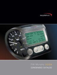
Hummingbird's <strong>Speedometer</strong> <strong>Calibrator</strong><br />
corrects signals from both hall-effect and<br />
inductive speed sensors, compensating for<br />
both manufacturer and user induced errors.<br />
Electronic systems in vehicles, require<br />
accurate speed information to operate<br />
correctly. Hummingbird's simple to install<br />
<strong>Speedometer</strong> <strong>Calibrator</strong> corrects for common<br />
sources of error and provides accurate speed<br />
without having to change the mechanics of<br />
the vehicle.<br />
Powerful Performance<br />
Designed for harsh automotive environments,<br />
the module features transient voltage<br />
protection on the supply and short circuit<br />
protected outputs. The unit is designed to<br />
work from 6V to 30V and so is suitable for use<br />
in motorcycles, cars and trucks.<br />
Common sources of speed error include:<br />
● 2% to 10% error direct from the manufacturer<br />
● Change of wheel or tyre size<br />
● Gearing changes: sprockets, differentials etc.<br />
● Replacement of gearbox, engine or<br />
differential<br />
● Instrument cluster / speedo faceplate change<br />
The <strong>Speedometer</strong> <strong>Calibrator</strong> is able to<br />
compensate for signal errors by dividing the<br />
input signal down to as low as 1/8th and up to<br />
as high as 8 times in 0.1% increments.<br />
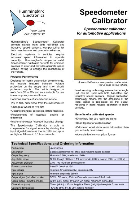
Speedo <strong>Calibrator</strong> – true speed no matter what<br />
you've done to your vehicle<br />
Level sensing technology means that a single<br />
unit can be used with both hall-effect and<br />
inductive speed sensors. Signal duplication<br />
technology means that the amplitude of the<br />
input signal is replicated on the output<br />
resulting in more reliable operation in more<br />
vehicles.<br />
Benefits of a calibrated speedo<br />
•Know how fast you really are going<br />
•Road legal after customisation<br />
•Odometer won't show more kilometers than<br />
you actually have driven<br />
● Accurate fuel consumption figures<br />
Technical Specifications and Ordering Information<br />
Part number<br />
HMSC8000A<br />
Description<br />
Speed calibrator for hall effect and inductive speed sensors<br />
Output frequency<br />
Minimum 0.5Hz, maximum 10kHz<br />
Adjustable range<br />
12.5% though 800% in 0.1% increments (200Hz can be 25Hz to 1600Hz)<br />
Adjustment precision<br />
0.1% - via multi-turn potentiometer<br />
Power consumption<br />
240mW, 20mA at 12V<br />
Input voltage<br />
minimum for operation 6V; maximum 30V<br />
Input signal<br />
minimum amplitude 250mV<br />
Output signal (hall effect mode)<br />
Output signal (inductive mode)<br />
Dimensions (mm)<br />
0/5V in 5V mode; 0/Vin in Vin mode; maximum 25mA tel: +61 drain(0)2 8006 2121<br />
±2.5V in 5V mode; ±Vin/2 in Vin www.hummingbirdelectronics.com.au<br />
mode; maximum 10mA drain<br />
35mm (width) x 35mm (length) info@hummingbirdelectronics.com.au<br />
x 20mm (height) – baseplate 51mm wide<br />
Operating temperature<br />
-40 o C to 85 o C; 5% to 95% relative humidity
<strong>Speedometer</strong><br />
<strong>Calibrator</strong><br />
Setup instructions<br />
Installation of a <strong>Speedometer</strong> <strong>Calibrator</strong> is<br />
straightforward as long as a few critical points<br />
are noted. Critical items will be highlighted in<br />
bold italics in this document for your quick<br />
reference.<br />
+<br />
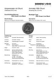
Changing the calibration value<br />
1) Identify the fine adjustment screw. Turn<br />
the screw clockwise to increase the<br />
multiplication factor and anti-clockwise to<br />
decrease it.<br />
3) For more coarse adjustment, change the<br />
multiplication factor by inserting the link<br />
provided on either pins 1&2 or pins 2&3<br />
according to the table below.<br />
Link Output range<br />
open 0.5 to 2 times input<br />
1-2 0.125 to 0.5 times input<br />
2-3 2 to 8 times input<br />
-<br />
Works with hall-effect and inductive sensors<br />
Installation Instructions<br />
1) Connect positive power to the red wire<br />
and ground to the black wire. Some speed<br />
senders have a local power supply, and it may<br />
be possible to use this supply to power the<br />
unit.<br />
2) The inductive or hall effect pulse output<br />
from the existing speed sender should be<br />
connected to the yellow wire on the<br />
speedometer calibrator.<br />
3) The green wire from the speedometer<br />
calibrator goes to the speedometer which<br />
needs to be calibrated.<br />
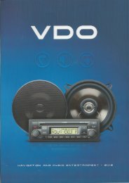
Changing the sensor type<br />
1) Open the unit by unscrewing the two<br />
screws on the rear of the unit.<br />
2) Change the switch settings according to<br />
the table below to select the correct output<br />
mode.<br />
Function On Off<br />
Switch 1 sensor type Hall-effect Inductive<br />
Switch 2 output amplitude Vin 5V<br />
Example – inductive in, inductive out, divide by 4<br />
Pin 1 Pin 4<br />
adjust screw<br />
amplitude<br />
mode<br />
Internal view with cover removed<br />
tel: +61 (0)2 8006 2121<br />
www.hummingbirdelectronics.com.au<br />
info@hummingbirdelectronics.com.au