Camera Gimbal Control System for Unmanned Platforms
Camera Gimbal Control System for Unmanned Platforms
Camera Gimbal Control System for Unmanned Platforms

Create successful ePaper yourself
Turn your PDF publications into a flip-book with our unique Google optimized e-Paper software.
7th International DAAAM Baltic Conference<br />
"INDUSTRIAL ENGINEERING<br />
22-24 April 2010, Tallinn, Estonia<br />
CAMERA GIMBAL CONTROL SYSTEM FOR UNMANNED<br />
PLATFORMS<br />
Tiimus, K. & Tamre, M.<br />
Abstract: This paper gives an overview of<br />
a gyro-stabilized motion control system <strong>for</strong><br />
camera gimbals designed <strong>for</strong> unmanned<br />
systems. The original mechanism was<br />
initially developed <strong>for</strong> medium sized<br />
remotely piloted helicopters, but the system<br />
has now gone through a 2nd development<br />
stage and there<strong>for</strong>e can be implemented<br />
into both smaller and larger applications<br />
ranging from miniature UAV systems to<br />
large scale observation plat<strong>for</strong>ms. The<br />
functioning prototype gimbal mehcanism<br />
has a 3 axis design driven by gearhead DC<br />
motors with incremental encoder feedback<br />
and AHRS unit <strong>for</strong> angular movement<br />
corrections.<br />
Key words: UAV, camera gimbal, IMU,<br />
AHRS, remotely piloted helicopter, motion<br />
control system.<br />
1. INTRODUCTION<br />
The aim of this project was to develop a<br />
gyro-stabilized camera control system that<br />
could be adapted into various types of<br />
camera stabilization mechanism of<br />
unmanned aerial vehicles. The reasearch<br />
and development in the field of mechanical<br />
and electrical engineering have led to a<br />
rapid upgrade in the market of available<br />
system components, which can be used as<br />
key elements in this type of electromechanical<br />
system. Some of the notable<br />
components that have gone through<br />
significant improvement processes during<br />
the recent past are:<br />
• Attitude and Heading Reference<br />
<strong>System</strong>s (AHRS)<br />
• DC gearhed motors with integrated<br />
incremental encoders<br />
• Modular ultra high resolution<br />
miniature incremental encoders<br />
• Fast and capable microprocessor<br />
systems and single board computers<br />
(ARM technology <strong>for</strong> example)<br />
Other highly important factors, which help<br />
to design and manufcature a system of<br />
moderate complicity, are 3D CAD<br />
programs like Solid Edge with Syncronous<br />
Tehcnology and availability of instant<br />
CNC machining to manufacture the<br />
prototype of the designed system.<br />
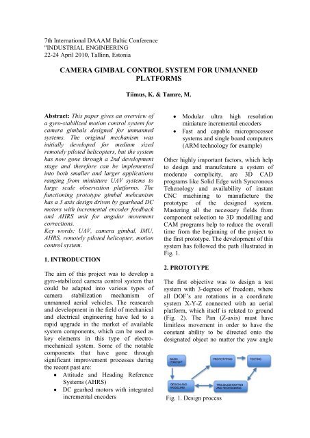
Mastering all the necessary fields from<br />
component selection to 3D modelling and<br />
CAM programs help to reduce the overall<br />
time from the beginning of the project to<br />
the first prototype. The development of this<br />
system has followed the path illustrated in<br />
Fig. 1.<br />
2. PROTOTYPE<br />
The first objective was to design a test<br />
system with 3-degrees of freedom, where<br />
all DOF’s are rotations in a coordinate<br />
system X-Y-Z connected with an aerial<br />
plat<strong>for</strong>m, which itself is related to ground<br />
(Fig. 2). The Pan (Z-axis) must have<br />
limitless movement in order to have the<br />
constant ability to be directed onto the<br />
designated object no matter the yaw angle<br />
Fig. 1. Design process
Fig. 3. Coordinate system 0 - ground, 1<br />
- air vehicle, 2 - camera gimbal<br />
of the plat<strong>for</strong>m. Tilt and roll axes (Y and<br />
X) rotational movement range depends<br />
higly on the pitch and roll movements of<br />
the aerial vehicle and also the task of the<br />
gimbal. For example if a gimbal <strong>for</strong> a<br />
photocamera had a roll axis movement<br />
range of ±90 degrees and an additional 10<br />
degrees of stabilization overlay, it could<br />
easily be used to take Portrait and<br />
Landscape pictures during the same flight<br />
without the need to mechanically<br />
reposition the camera.<br />
An important point was to keep in mind<br />
that the system must have the ability to be<br />
implemented in mechanisms of very<br />
different size and purpose. No matter if it is<br />
a 1, 2 or 3 axis mechanism, miniature,<br />
medium or large sized, <strong>for</strong> stabilizing a<br />
video- or photocamera or other sensorics<br />
like spectrometers – the same core system<br />
can be used and reconfigured with ease.<br />
All things considered, the most suitable<br />
flying plat<strong>for</strong>m <strong>for</strong> a first prototype was a<br />
remotely piloted helicopter as it can hover<br />
and move very slowly and thus makes an<br />
ideal solution to develop the camera<br />
gimbal system and tune its parameters.<br />
Hereby a 3 axis mechanism <strong>for</strong> a Canon<br />
DSLR camera was decided to be built as<br />
the prototype mechanism.<br />
The gimbal should actively compensate the<br />
rotational movements of the helicopter it is<br />
mounted on. Two of the main aspects in<br />
all motion control systems with similar<br />
tasks are position feedback and position<br />
reference data. Feedback tells us where the<br />
mechanism is, reference tells us where the<br />
mechanism has to be. The resolution of the<br />
feedback device along with the update<br />
frequency and accuracy of the reference<br />
unit are essential figures if a smooth and<br />
precise system is conseptualized. The<br />
kinematics scheme, mechanical properties<br />
and quality of the components and<br />
assembly determine the final quality of the<br />
system.<br />
2.1 Kinematics scheme<br />
The 3 axes of the prototype system<br />
compensate all the angular movements of<br />
the hull it is attached to and the general<br />
principle of the axes arrangement assure it<br />
is able to avoid the gimbal lock state during<br />
its normal operation. The configuration -<br />
pan over tilt over roll (Fig. 3) - allows up<br />
to 90 degrees of roll or pitch movement by<br />
the aircraft be<strong>for</strong>e a gimbal lock occurs,<br />
which of course is highly unlike to ever<br />
happen.<br />
2.2 Rotational movement feedback<br />
A simple camera control mechanism<br />
(camera gimbal) has 2 degrees of freedom<br />
– pan and tilt, that are driven by actuators<br />
which, incase of manual control, do not<br />
necessarily need to have any sorts of<br />
feedback (e.g. security camera gimbal in a<br />
supermarket). Now if we want precise<br />
in<strong>for</strong>mation regarding the cameras<br />
rotational movement, we must have either<br />
analog or digital feedback units installed,<br />
that detect rotational movement of the<br />
gimbals axis. Analog rotational movement<br />
detectors are called potentiometers, they<br />
output voltage, digital ones are called<br />
Fig. 2. Kinematics scheme showing 3<br />
revolute joints
otational encoders, which output binary<br />
code. Potentiometers may cause drift as<br />
they are quite temperature sensitive and<br />
they normally have rotational limits and<br />
there<strong>for</strong>e not being able to provide<br />
continuous rotation in certain needed<br />
situations - pan axis <strong>for</strong> example.<br />
Rotational encoders, on the other hand,<br />
have no drift and no limits regarding<br />
rotational movement. They lack drift as the<br />
output is a digital signal, which is in direct<br />
line relationship with the encoders<br />
resolution and the movement angle of the<br />
encoders axis.<br />
Rotational encoders output can either be<br />
absolute or incremental, with absolute<br />
having a unique binary code <strong>for</strong> every<br />
position and thus the number of contact<br />
wires increases in conjunction with the<br />
resolution. Incremental encoders on the<br />
opposite have usually only 2 channels and<br />
2 signal wires that give out readings<br />
regarding the direction and increments of<br />
the rotational movement.<br />
Both encoder types come in various sizes<br />
and configurations and both have<br />
advantages and disadvantages in different<br />
fields of usage. In small and miniature<br />
camera gimbal mechanism however, a<br />
incremental encoder type has better<br />
features than absolute encoder especially<br />
by having a significantly better size to<br />
resolution ratio and this is the main reason<br />
why incremental encoders were chosen to<br />
be utilized in the described camera control<br />
system.<br />
2.3 Initial absolute positioning<br />
The described system can use different<br />
types of incremental encoders – <strong>for</strong><br />
example modular encoders that may be<br />
installed to the gimbals output axis in<br />
various configurations, or integrated<br />
encoders, which already are assembled into<br />
the end shaft of a planetary gearhead<br />
motor. In most cases, incremental encoders<br />
Fig. 4. Opto switch and interrupt disc<br />
<strong>for</strong> axis absolute positioning<br />
need to be zeroed, or in other words, they<br />
need to know their home position about<br />
what the relative position feedback is given<br />
to.<br />
Using an optical switch and an interrupt<br />
disc (Fig. 4), which determines the state of<br />
the axis right after the power up of the<br />
system, solves the homing of each<br />
individual axis. The optical switch has a<br />
binary output, so if the interrupt discs<br />
separator line is mechanically aligned to 0<br />
degrees, the direction the axis needs to be<br />
moved after power up is known and when<br />
the optical switch registers a binary signal<br />
transition, the home position is reached and<br />
the incremental encoders offset will be<br />
zeroed.<br />
2.4 Positional reference system<br />
Another highly important device is an<br />
Attitude and Heading Reference <strong>System</strong> or<br />
simply AHRS, which provides data about<br />
the attitude change and the heading of a<br />
rigid system. The accuracy and update rate<br />
of the unit determine how fast and precise<br />
is the registering of change in attitude and<br />
heading and how often can correctional<br />
data be sent from the main controller to the<br />
motor controllers. The most suitable AHRS<br />
<strong>for</strong> this project was a SBG <strong>System</strong>s IG-<br />
500 A that has 100 Hz update rate and +/-<br />
1 degree error margin.
Apart from the mechanical stiffness of the<br />
mechanism, the feedback resolution and<br />
precision of the AHRS are the main<br />
parameters that determine the possible<br />
accuracy of the completed camera gimbal.<br />
2.5 Prototype mechanism<br />
After the basic calculations <strong>for</strong> moment of<br />
inertia of each axis and motor selection, the<br />
gimbal was modeled in Solid Edge ST<br />
(Fig. 5).<br />
The gimbal consists of three subassemblies<br />
that divide into smaller<br />
segments. The whole device is constructed<br />
Fig. 5. Testing mechanism <strong>for</strong> integrating<br />
a slip-ring module<br />
to be very modular and easily<br />
reconfigurable incase a component needs<br />
to be replaced. A variety of different DC<br />
motors, encoders and transmissions were<br />
tested be<strong>for</strong>e an acceptable solution was<br />
reached and testing could start.<br />
Roll and tilt axis use the same motors and<br />
bevel gear transmissions to assure the<br />
unified movements of the tilting axes. Pan<br />
axis has a worm gear transmission and a<br />
high-speed motor. The self-braking worm<br />
gear takes the load coming from sudden<br />
pan axis decelerations and prevents the<br />
transmission to break incase of an under<br />
slung configuration on a RC helicopter.<br />
As the pan axis has limitless movement<br />
capability, it is equipped with a slip-ring<br />
(Fig. 6) <strong>for</strong> the power and signal contacts<br />
in roll and tilt sub-assemblies and all the<br />
control signals [ 4 ].<br />
2.6 Vibration<br />
The helicopter has 4 main vibration<br />
sources: main rotor, tail rotor, electric<br />
motor and transmissions. The motor, tail<br />
rotor and transmissions have relatively low<br />
vibrations compared to vibrations coming<br />
from the main rotor and their effect to the<br />
cameras sensor is minimal.<br />
Fig. 6. Assemblies of the prototype<br />
gimbal<br />
The only considerable vibration source is<br />
the main rotor which spins about<br />
1500…2000 rpm having a frequency of<br />
25…33.3 Hz. It is very hard to measure the<br />
vibration and take every different situation
into account – mass of the camera, angle of<br />
the main blades etc. and the fastest way to<br />
find a solution <strong>for</strong> vibration dampening is<br />
by trial and error.<br />
There are a few good sources <strong>for</strong><br />
in<strong>for</strong>mation about wire rope isolators [ 1 ],<br />
[ 2 ]. For the prototype a custom wire rope<br />
isolator with exchangeable and extendable<br />
wire rope was designed.<br />
2.7 Motor controllers<br />
Combining the DC motors, encoders and<br />
opto switches was another major task [ 3 ].<br />
In order to assure that different sized<br />
motors with varying input voltage and<br />
power could be used, an all-in-one motor<br />
controller was designed. The controller has<br />
a Silabs 8051 series processor type F310<br />
and a BD6231F H-bridge, which can drive<br />
6-24 V motors and give output current up<br />
to 1 A. The principle of the motor<br />
controller is shown on Fig. 7. It has 2<br />
separate communications protocols <strong>for</strong><br />
added functionality – UART and I 2 C. The<br />
same motor controller can be used with a<br />
DC planetary gearhead motor equipped<br />
with an integrated encoder, or a suitable<br />
DC motor and an external modular encoder<br />
(Figs. 8-9), depending on the configuration<br />
of the system. Different motors can be used<br />
as long as the supply voltage and current<br />
consumption are within limits.<br />
2.8 Main <strong>Control</strong>ler<br />
All of the above must be joined with a<br />
main controller unit. The main controller<br />
has to be able to per<strong>for</strong>m matrix<br />
Fig. 9. Block diagram of motor<br />
controller<br />
calculations, read the AHRS output and<br />
Fig. 7. Motor controller with an<br />
integrated encoder/motor<br />
Fig. 8. Motor controller with modular<br />
encoder<br />
communicate with a data modem and<br />
motor controllers. In order to do that 2<br />
UART and I 2 C protocols was needed.<br />
There were 2 suitable single board<br />
computers – Beagle Board and Gumstix<br />
Overo. Both are based on ARM Cortex A8<br />
processors, which have excellent efficiency<br />
and are widely used in many multimedia<br />
applications like Smart-phones, GPS<br />
devices and PDA’s. Gumstix has extension<br />
options <strong>for</strong> WiFi and Bluetooth and smaller<br />
overall dimensions.<br />
3. FUTURE DEVELOPMENTS<br />
The prototype <strong>for</strong> the remotely piloted<br />
helicopter has gone through extensive<br />
testing and some major changes to improve<br />
the per<strong>for</strong>mance of the system. One notable<br />
change is the replacement of the worm gear<br />
pan axis with a bevel gear design identical<br />
to Tilt and Roll axes.<br />
The system has also been used in smaller<br />
test plat<strong>for</strong>ms <strong>for</strong> airplanes. A 2-axis<br />
miniature camera gimbal, 1 axis photo<br />
camera stabilization mechanism and a<br />
mechanism <strong>for</strong> targeting a directional
antenna has been tested with the same<br />
system. Designing a medium sized duocamera<br />
gimbal is in progress. All is done<br />
with the same system by only changing the<br />
axis layouts, selecting appropriate<br />
motors/encoders and setting up the system<br />
with suitable parameters.<br />
4. CONCLUSION<br />
As a conclusion, a multi-axis motion<br />
control system <strong>for</strong> different purposes was<br />
developed (Fig. 10). The described system<br />
has a very flexible configuration option<br />
meaning that it can be used in many<br />
mechanisms that need motion control.<br />
Apart from its primary purpose of<br />
controlling camera gimbals, it can be used<br />
<strong>for</strong> leveling or moving sensors like<br />
spectrometers, laser rangefinders,<br />
directional antennas etc.<br />
Further research and development must be<br />
done to work out the best methodology <strong>for</strong><br />
setting the correct operating parameters of<br />
the main controller and DC motor<br />
controllers via a user-friendly configutation<br />
wizard and to design more stabilization<br />
plat<strong>for</strong>ms <strong>for</strong> testing the different settings.<br />
The final outcome of this research project<br />
is a higly adaptable, fully configurable<br />
motion control system <strong>for</strong> a wide range of<br />
sensors that can be used in general<br />
purposes like aerial photo- and<br />
videography or narrow fields like power<br />
line inspections, heightmap generation <strong>for</strong><br />
mining pit examinations, <strong>for</strong>est data<br />
cathering with spectrometers, post <strong>for</strong>est<br />
fire inspection with thermal cameras,<br />
military and police surveillance etc.<br />
5. ACKNOWLEDGMENTS<br />
This work was supported by Doctoral<br />
School of Energy and Geotechnology II<br />
and Estonian Ministry of Education and<br />
Research Project SF0140113Bs08.<br />
6. REFERENCES<br />
1. ITT - Enidine Inc. wire rope catalogue<br />
http://www.enidineaviation.com/PDFS/WireRopeCatalog.<br />
pdf<br />
2. J. DeBruin, SHOCK ISOLATION FOR<br />
MOBILE POINTED SATCOM<br />
SYSTEMS<br />
http://202.194.20.8/proc/MILCOM08/<br />
Milcom08/pdfs/1617.pdf<br />
3. G. Maiocchi, DRIVNING DC<br />
MOTORS<br />
http://www.st.com/stonline/books/pdf/<br />
docs/1704.pdf<br />
4. F. Magnussen , E. Nordlund, S.<br />
Châtelet, C. Sadarangani,<br />
MEASUREMENTS ON SLIP RING<br />
UNITS FOR CHARACTERIZATION<br />
OF PERFORMANCE, Royal Institute<br />
of Technology (KTH), Sweden<br />
5. K. Tiimus, Gyrostabilized camera<br />
gimbal <strong>for</strong> remotely piloted helicopter<br />
Masters Thesis. Tallinn University of<br />
Technology, Tallinn 2009<br />
6. CORRESPONDING ADDRESS<br />
Kristjan Tiimus. Department of<br />
Mechatronics, Tallinn University of<br />
Technology.<br />
Address: Ehitajate tee 5, 19086 Tallinn,<br />
Estonia.<br />
Phone: +372 5177186<br />
E-mail: kristjan@helicam.ee<br />
Fig. 10. Remotely piloted plat<strong>for</strong>m with 3-axis prototype gimbal