Timber Hangers for I-Joists HITB ITB - Simpson Strong-Tie
Timber Hangers for I-Joists HITB ITB - Simpson Strong-Tie
Timber Hangers for I-Joists HITB ITB - Simpson Strong-Tie

Create successful ePaper yourself
Turn your PDF publications into a flip-book with our unique Google optimized e-Paper software.
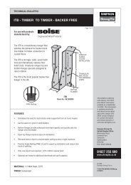
<strong>Timber</strong> <strong>Hangers</strong> <strong>for</strong> I-<strong>Joists</strong><br />
<strong>ITB</strong>/<strong>H<strong>ITB</strong></strong> I-Joist Hanger<br />
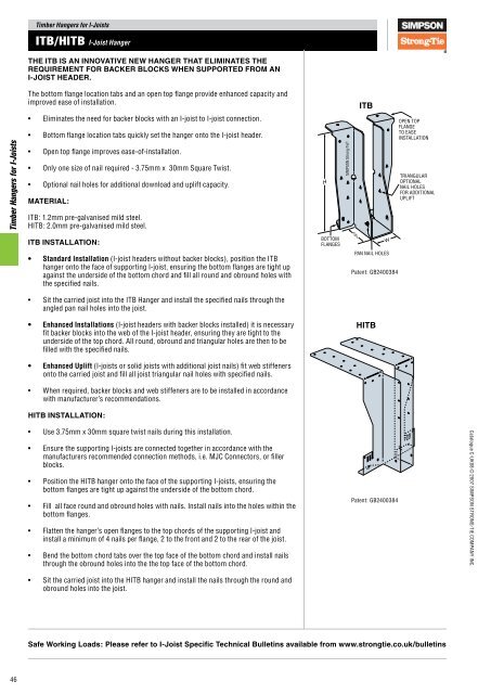
THE <strong>ITB</strong> IS AN INNOVATIVE NEW HANGER THAT ELIMINATES THE<br />
REQUIREMENT FOR BACKER BLOCKS WHEN SUPPORTED FROM AN<br />
I-JOIST HEADER.<br />
The bottom flange location tabs and an open top flange provide enhanced capacity and<br />
improved ease of installation.<br />
<strong>ITB</strong><br />
•<br />
•<br />
Eliminates the need <strong>for</strong> backer blocks with an I-joist to I-joist connection.<br />
Bottom flange location tabs quickly set the hanger onto the I-joist header.<br />
OPEN TOP<br />
FLANGE<br />
TO EASE<br />
INSTALLATION<br />
<strong>Timber</strong> <strong>Hangers</strong> <strong>for</strong> I-<strong>Joists</strong><br />
•<br />
•<br />
•<br />
Open top flange improves ease-of-installation.<br />
Only one size of nail required - 3.75mm x 30mm Square Twist.<br />
Optional nail holes <strong>for</strong> additional download and uplift capacity.<br />
MATERIAL:<br />
<strong>ITB</strong>: 1.2mm pre-galvanised mild steel.<br />
<strong>H<strong>ITB</strong></strong>: 2.0mm pre-galvanised mild steel.<br />
H<br />
TRIANGULAR<br />
OPTIONAL<br />
NAIL HOLES<br />
FOR ADDITIONAL<br />
UPLIFT<br />
<strong>ITB</strong> INSTALLATION:<br />
BOTTOM<br />
FLANGES<br />
50<br />
W<br />
• Standard Installation (I-joist headers without backer blocks), position the <strong>ITB</strong><br />
hanger onto the face of supporting I-joist, ensuring the bottom flanges are tight up<br />
against the underside of the bottom chord and fill all round and obround holes with<br />
the specified nails.<br />
PAN NAIL HOLES<br />
Patent: GB2400384<br />
•<br />
Sit the carried joist into the <strong>ITB</strong> Hanger and install the specified nails through the<br />
angled pan nail holes into the joist.<br />
• Enhanced Installations (I-joist headers with backer blocks installed) it is necessary<br />
fit backer blocks into the web of the I-joist header, ensuring they are tight to the<br />
underside of the top chord. All round, obround and triangular holes are then to be<br />
filled with the specified nails.<br />
<strong>H<strong>ITB</strong></strong><br />
• Enhanced Uplift (I-joists or solid joists with additional joist nails) fit web stiffeners<br />
onto the carried joist and fill all joist triangular nail holes with specified nails.<br />
•<br />
When required, backer blocks and web stiffeners are to be installed in accordance<br />
with manufacturer’s recommendations.<br />
<strong>H<strong>ITB</strong></strong> INSTALLATION:<br />
•<br />
•<br />
•<br />
•<br />
•<br />
•<br />
Use 3.75mm x 30mm square twist nails during this installation.<br />
Ensure the supporting I-joists are connected together in accordance with the<br />
manufacturers recommended connection methods, i.e. MJC Connectors, or filler<br />
blocks.<br />
Position the <strong>H<strong>ITB</strong></strong> hanger onto the face of the supporting I-joists, ensuring the<br />
bottom flanges are tight up against the underside of the bottom chord.<br />
Fill all face round and obround holes with nails. Install nails into the holes within the<br />
bottom flanges.<br />
Flatten the hanger’s open flanges to the top chords of the supporting I-joist and<br />
install a minimum of 4 nails per flange, 2 to the front and 2 to the rear of the joist.<br />
Bend the bottom chord tabs over the top face of the bottom chord and install nails<br />
through the obround holes into the the top face of the bottom chord.<br />
Patent: GB2400384<br />
Catalogue C-UK08 © 2007 SIMPSON STRONG-TIE COMPANY INC.<br />
•<br />
Sit the carried joist into the <strong>H<strong>ITB</strong></strong> hanger and install the nails through the round and<br />
obround holes into the joist.<br />
Safe Working Loads: Please refer to I-Joist Specific Technical Bulletins available from www.strongtie.co.uk/bulletins<br />
46
<strong>Timber</strong> <strong>Hangers</strong> <strong>for</strong> I-<strong>Joists</strong><br />
<strong>ITB</strong>/<strong>H<strong>ITB</strong></strong> I-Joist Hanger<br />
<strong>ITB</strong> <strong>Hangers</strong> <strong>for</strong> <strong>Timber</strong> I-<strong>Joists</strong><br />
Joist<br />
Width<br />
(mm)<br />
Model No.<br />
Height (H)<br />
Dimension (mm)<br />
Width (W)<br />
Typical <strong>ITB</strong> Installation<br />
<strong>ITB</strong>195/40 195 40<br />
<strong>ITB</strong>200/40 200 40<br />
38<br />
45<br />
<strong>ITB</strong>220/40 220 40<br />
<strong>ITB</strong>240/40 240 40<br />
<strong>ITB</strong>300/40 300 40<br />
<strong>ITB</strong>145/47 145 47<br />
<strong>ITB</strong>195/47 195 47<br />
<strong>ITB</strong>200/47 200 47<br />
<strong>ITB</strong>220/47 220 47<br />
<strong>ITB</strong>240/47 240 47<br />
<strong>ITB</strong>245/47 245 47<br />
SUPPORTING<br />
I-JOIST<br />
PAN NAIL<br />
HOLES<br />
CARRIED<br />
I-JOIST<br />
<strong>Timber</strong> <strong>Hangers</strong> <strong>for</strong> I-<strong>Joists</strong><br />
<strong>ITB</strong>300/47 300 47<br />
51<br />
<strong>ITB</strong>240/53 240 53<br />
<strong>ITB</strong>300/53 300 53<br />
<strong>ITB</strong>195/61 195 61<br />
Typical <strong>H<strong>ITB</strong></strong> Installation<br />
<strong>ITB</strong>200/61 200 61<br />
58-60<br />
<strong>ITB</strong>220/61 220 61<br />
<strong>ITB</strong>240/61 240 61<br />
<strong>ITB</strong>245/61 245 61<br />
<strong>ITB</strong>300/61 300 61<br />
<strong>ITB</strong>220/66 220 66<br />
63<br />
<strong>ITB</strong>240/66 240 66<br />
<strong>ITB</strong>300/66 300 66<br />
<strong>ITB</strong>195/75 195 75<br />
72<br />
<strong>ITB</strong>220/75 220 75<br />
<strong>ITB</strong>245/75 245 75<br />
<strong>ITB</strong>300/75 300 75<br />
Catalogue C-UK08 © 2007 SIMPSON STRONG-TIE COMPANY INC.<br />
2ply 38<br />
89<br />
<strong>ITB</strong>195/78 195 78<br />
<strong>ITB</strong>200/78 200 78<br />
<strong>ITB</strong>220/78 220 78<br />
<strong>ITB</strong>240/78 240 78<br />
<strong>ITB</strong>300/78 300 78<br />
<strong>ITB</strong>195/91 195 91<br />
<strong>ITB</strong>200/91 200 91<br />
<strong>ITB</strong>220/91 220 91<br />
<strong>ITB</strong>240/91 240 91<br />
<strong>ITB</strong>245/91 245 91<br />
<strong>ITB</strong>300/91 300 91<br />
<strong>ITB</strong>195/100 195 100<br />
Enhanced <strong>ITB</strong> Installation<br />
97<br />
<strong>ITB</strong>220/100 220 100<br />
<strong>ITB</strong>245/100 245 100<br />
<strong>ITB</strong>300/100 300 100<br />
PAN NAIL<br />
SUPPORTING<br />
HOLES<br />
I-JOIST<br />
BACKER BLOCKS<br />
REQUIRED<br />
FOR ENHANCED<br />
DOWNLOAD ONLY<br />
WEB STIFFENER<br />
REQUIRED<br />
FOR ENHANCED<br />
UPLIFT ONLY<br />
CARRIED<br />
I-JOIST<br />
47
<strong>Timber</strong> <strong>Hangers</strong> <strong>for</strong> I-<strong>Joists</strong><br />
<strong>ITB</strong>/<strong>H<strong>ITB</strong></strong> I-Joist Hanger<br />
<strong>H<strong>ITB</strong></strong> <strong>Hangers</strong> <strong>Timber</strong> I-<strong>Joists</strong><br />
With LVL Flanges<br />
<strong>H<strong>ITB</strong></strong> <strong>Hangers</strong> <strong>Timber</strong> I-<strong>Joists</strong><br />
With Solid Sawn Flanges<br />
Joist<br />
Width<br />
(mm)<br />
Model No.<br />
Height (H)<br />
Dimension (mm)<br />
Width (W)<br />
Joist<br />
Width<br />
(mm)<br />
Model No.<br />
Height (H)<br />
Dimension (mm)<br />
Width (W)<br />
<strong>H<strong>ITB</strong></strong>200/40 200 40<br />
<strong>H<strong>ITB</strong></strong>-LT195/47 195 47<br />
<strong>Timber</strong> <strong>Hangers</strong> <strong>for</strong> I-<strong>Joists</strong><br />
40<br />
45<br />
51<br />
<strong>H<strong>ITB</strong></strong>220/40 220 40<br />
<strong>H<strong>ITB</strong></strong>240/40 240 40<br />
<strong>H<strong>ITB</strong></strong>300/40 300 40<br />
<strong>H<strong>ITB</strong></strong>200/47 200 47<br />
<strong>H<strong>ITB</strong></strong>220/47 220 47<br />
<strong>H<strong>ITB</strong></strong>240/47 240 47<br />
<strong>H<strong>ITB</strong></strong>300/47 300 47<br />
<strong>H<strong>ITB</strong></strong>240/53 240 53<br />
<strong>H<strong>ITB</strong></strong>300/53 300 53<br />
45<br />
<strong>H<strong>ITB</strong></strong>-LT200/47 200 47<br />
<strong>H<strong>ITB</strong></strong>-LT220/47 220 47<br />
<strong>H<strong>ITB</strong></strong>-LT235/47 235 47<br />
<strong>H<strong>ITB</strong></strong>-LT240/47 240 47<br />
<strong>H<strong>ITB</strong></strong>-LT245/47 245 47<br />
<strong>H<strong>ITB</strong></strong>-LT300/47 300 47<br />
<strong>H<strong>ITB</strong></strong>-LT195/61 195 61<br />
<strong>H<strong>ITB</strong></strong>-LT200/61 200 61<br />
<strong>H<strong>ITB</strong></strong>-LT220/61 220 61<br />
<strong>H<strong>ITB</strong></strong>200/61 200 61<br />
60<br />
<strong>H<strong>ITB</strong></strong>-LT235/61 235 61<br />
58<br />
<strong>H<strong>ITB</strong></strong>220/61 220 61<br />
<strong>H<strong>ITB</strong></strong>240/61 240 61<br />
<strong>H<strong>ITB</strong></strong>-LT240/61 240 61<br />
<strong>H<strong>ITB</strong></strong>-LT245/61 245 61<br />
<strong>H<strong>ITB</strong></strong>300/61 300 61<br />
<strong>H<strong>ITB</strong></strong>-LT300/61 300 61<br />
<strong>H<strong>ITB</strong></strong>220/66 220 66<br />
<strong>H<strong>ITB</strong></strong>-LT195/75 195 75<br />
63<br />
<strong>H<strong>ITB</strong></strong>240/66 240 66<br />
<strong>H<strong>ITB</strong></strong>-LT220/75 220 75<br />
<strong>H<strong>ITB</strong></strong>300/66 300 66<br />
72<br />
<strong>H<strong>ITB</strong></strong>-LT235/75 235 75<br />
<strong>H<strong>ITB</strong></strong>200/78 200 78<br />
<strong>H<strong>ITB</strong></strong>-LT245/75 245 75<br />
2ply 38<br />
<strong>H<strong>ITB</strong></strong>220/78 220 78<br />
<strong>H<strong>ITB</strong></strong>240/78 240 78<br />
<strong>H<strong>ITB</strong></strong>-LT300/75 300 75<br />
<strong>H<strong>ITB</strong></strong>-LT195/91 195 91<br />
<strong>H<strong>ITB</strong></strong>300/78 300 78<br />
<strong>H<strong>ITB</strong></strong>-LT200/91 200 91<br />
89<br />
<strong>H<strong>ITB</strong></strong>200/91 200 91<br />
<strong>H<strong>ITB</strong></strong>220/91 220 91<br />
<strong>H<strong>ITB</strong></strong>240/91 240 91<br />
<strong>H<strong>ITB</strong></strong>300/91 300 91<br />
Typical <strong>H<strong>ITB</strong></strong><br />
Installation<br />
89<br />
97<br />
<strong>H<strong>ITB</strong></strong>-LT220/91 220 91<br />
<strong>H<strong>ITB</strong></strong>-LT235/91 235 91<br />
<strong>H<strong>ITB</strong></strong>-LT240/91 240 91<br />
<strong>H<strong>ITB</strong></strong>-LT245/91 245 91<br />
<strong>H<strong>ITB</strong></strong>-LT195/100 195 100<br />
<strong>H<strong>ITB</strong></strong>-LT220/100 220 100<br />
<strong>H<strong>ITB</strong></strong>-LT235/100 235 100<br />
<strong>H<strong>ITB</strong></strong>-LT245/100 245 100<br />
<strong>H<strong>ITB</strong></strong>-LT300/100 300 100<br />
Catalogue C-UK08 © 2007 SIMPSON STRONG-TIE COMPANY INC.<br />
48
<strong>Timber</strong> <strong>Hangers</strong> <strong>for</strong> I-<strong>Joists</strong><br />
MJC Multiple Joist Connector<br />
THE MULTI JOIST CONNECTOR (MJC) ALLOWS TWO JOISTS TO BE<br />
FIXED TOGETHER TO ACT AS A SINGLE UNIT, TRANSFERRING THE<br />
INCOMING LOAD FROM THE LOADED PLY TO THE UNLOADED PLY.<br />
The MJC is an improved solution to the traditional filler block detail, which historically<br />
has been time consuming to fit and difficult to check if fitted or if fitted correctly.<br />
MJC<br />
It’s simple and effective design allows one size of product to be used on any joist size –<br />
regardless of height or width.<br />
•<br />
•<br />
•<br />
•<br />
•<br />
Quick and simple to install.<br />
Safely joins multiple I-<strong>Joists</strong> together, allowing them to act as a single unit.<br />
Easy to see that MJC’s are installed (whereas filler blocks are invisible).<br />
One size product fits all joist height and width combinations.<br />
Just one nail size required: 3.75mm x 30mm square twist.<br />
<strong>Timber</strong> <strong>Hangers</strong> <strong>for</strong> I-<strong>Joists</strong><br />
MJC INSTALLATION SEQUENCE<br />
Stage 1:<br />
Position the MJC’s onto the 1st joist - ensuring that they<br />
are centred about the incoming load at 400 c/c (may be<br />
adjusted within 10mm each way).<br />
Please note that the connectors can be installed in any<br />
orientation. Secure each MJC with 4no. 3.75 x 30mm<br />
Square Twist Nails, to the top and bottom joist flanges as<br />
shown.<br />
Stage 2:<br />
Catalogue C-UK08 © 2007 SIMPSON STRONG-TIE COMPANY INC.<br />
Position 2nd joist ensuring ends are flush and joists are<br />
parallel.<br />
Secure the joist using 2no. 3.75 x 30mm Square Twist<br />
Nails per MJC into the top and bottom joist flanges as<br />
shown.<br />
NB - Loads can be found in <strong>Simpson</strong> <strong>Strong</strong>-<strong>Tie</strong> Technical<br />
Bulletin T-UK-MJC or visit www.strongtie.co.uk/bulletins.<br />
400 c/c<br />
49
<strong>Timber</strong> <strong>Hangers</strong> <strong>for</strong> I-<strong>Joists</strong><br />
<strong>ITB</strong>S Skewable I-Joist Hanger<br />
THE REVOLUTIONARY <strong>ITB</strong>S REDUCES BUILD COST, CONFUSION, SPEED<br />
OF INSTALLATION AND STOCK HOLDING.<br />
The <strong>ITB</strong>S solves the problem of skew hangers in timber to timber connections. It can be<br />
handed left or right on site by the carpenter, removing confusion when the floor is built<br />
opposite to the drawing. The <strong>ITB</strong>S is also fully adjustable from 22.5 to 67.5 deg skew,<br />
reducing the need <strong>for</strong> ‘special’ skew hangers. Finally, the <strong>ITB</strong>S is a Backer Free hanger<br />
removing the need <strong>for</strong> Backer Blocks in standard installation. Overall, the revolutionary<br />
<strong>ITB</strong>S reduces build cost, confusion, speed of installation and stock holding.<br />
<strong>ITB</strong>S<br />
<strong>Timber</strong> <strong>Hangers</strong> <strong>for</strong> I-<strong>Joists</strong><br />
•<br />
•<br />
•<br />
•<br />
•<br />
•<br />
45 deg skew, with site adjustable skew from 22.5 to 67.5 deg<br />
Non-handed hanger, can be left or right skew—adjusted on site, removing any<br />
handing confusion and reducing stock holding.<br />
Eliminates the need <strong>for</strong> backer blocks when supported from an I-joist header.<br />
Open top flange improves ease-of-installation.<br />
Only one size of nail required - 3.75 x 30mm.<br />
Can be used on I-joist or Solid Joist headers.<br />
•<br />
Optional nail holes <strong>for</strong> additional download.<br />
MATERIAL: 1.5mm thick Mild Steel.<br />
Safe Working Loads: Please refer to I-Joist Specific Technical Bulletins available from www.strongtie.co.uk/bulletins<br />
<strong>ITB</strong>S Skewable Hanger Sizes<br />
<strong>ITB</strong>S Skewable Hanger Sizes (Continued)<br />
Joist<br />
Width<br />
(mm)<br />
Model No.<br />
Height (H)<br />
Dimension (mm)<br />
Width (W)<br />
Joist<br />
Width<br />
(mm)<br />
Model No.<br />
Height (H)<br />
Dimension (mm)<br />
Width (W)<br />
40<br />
45<br />
51<br />
58-60<br />
66<br />
<strong>ITB</strong>S195/40 195 40<br />
<strong>ITB</strong>S200/40 200 40<br />
<strong>ITB</strong>S220/40 220 40<br />
<strong>ITB</strong>S240/40 240 40<br />
<strong>ITB</strong>S245/40 245 40<br />
<strong>ITB</strong>S301/40 301 40<br />
<strong>ITB</strong>S195/47 195 47<br />
<strong>ITB</strong>S200/47 200 47<br />
<strong>ITB</strong>S220/47 220 47<br />
<strong>ITB</strong>S240/47 240 47<br />
<strong>ITB</strong>S245/47 245 47<br />
<strong>ITB</strong>S301/47 301 47<br />
<strong>ITB</strong>S240/51 240 51<br />
<strong>ITB</strong>S301/51 301 51<br />
<strong>ITB</strong>S195/61 195 61<br />
<strong>ITB</strong>S200/61 200 61<br />
<strong>ITB</strong>S220/61 220 61<br />
<strong>ITB</strong>S240/61 240 61<br />
<strong>ITB</strong>S245/61 245 61<br />
<strong>ITB</strong>S301/61 301 61<br />
<strong>ITB</strong>S220/66 220 66<br />
<strong>ITB</strong>S240/66 240 66<br />
<strong>ITB</strong>S301/66 301 66<br />
<strong>ITB</strong>S195/75 195 75<br />
72<br />
<strong>ITB</strong>S220/75 220 75<br />
<strong>ITB</strong>S245/75 245 75<br />
<strong>ITB</strong>S301/75 301 75<br />
<strong>ITB</strong>S195/78 195 78<br />
<strong>ITB</strong>S200/78 200 78<br />
2ply 38<br />
<strong>ITB</strong>S220/78 220 78<br />
<strong>ITB</strong>S240/78 240 78<br />
<strong>ITB</strong>S245/78 245 78<br />
<strong>ITB</strong>S301/78 301 78<br />
<strong>ITB</strong>S195/91 195 91<br />
<strong>ITB</strong>S200/91 200 91<br />
89<br />
<strong>ITB</strong>S220/91 220 91<br />
<strong>ITB</strong>S240/91 240 91<br />
<strong>ITB</strong>S245/91 245 91<br />
<strong>ITB</strong>S301/91 301 91<br />
Enhanced <strong>ITB</strong>S Installation Standard <strong>ITB</strong>S Installation<br />
Catalogue C-UK08 © 2007 SIMPSON STRONG-TIE COMPANY INC.<br />
50
<strong>Timber</strong> <strong>Hangers</strong> <strong>for</strong> I-<strong>Joists</strong><br />
<strong>ITB</strong>S Skewable I-Joist Hanger<br />
STANDARD INSTALLATION SEQUENCE<br />
Stage 1<br />
Install the back plate onto the<br />
header in the required<br />
position. Ensure backer<br />
blocks are fitted if enhanced<br />
per<strong>for</strong>mance is required.<br />
Stage 2<br />
Secure the acute side of the<br />
backplate (inside angle) with<br />
the specified nails.<br />
<strong>Timber</strong> <strong>Hangers</strong> <strong>for</strong> I-<strong>Joists</strong><br />
Stage 3<br />
Adjust the angle of the<br />
backplate (if different from<br />
45) to suit the required<br />
angle. Use either adjustable<br />
set square or the guide tables<br />
shown on the right: Bend one<br />
time only.<br />
B<br />
B<br />
A<br />
Catalogue C-UK08 © 2007 SIMPSON STRONG-TIE COMPANY INC.<br />
Stage 5<br />
Offer the stirrup to the back<br />
plate ensuring it is located<br />
on the correct side (which<br />
can be either left or right<br />
hand side). Once all of the<br />
hooks (on the back plate) are<br />
clearly through the apertures<br />
(on the stirrup) slide in a<br />
downward direction ensuring<br />
all hooks engage onto the<br />
stirrup and click into position.<br />
Stage 4<br />
Secure the obtuse side of the<br />
back plate onto the header<br />
with all the specified nails,<br />
ensuring the face of the back<br />
plate is tight against the<br />
header.<br />
Stage 6<br />
Locate the floor joist into the<br />
stirrup ensuring the joist is<br />
set tight to the back of the<br />
stirrup. The joist should be<br />
secured into the stirrup with<br />
all specified nails on the open<br />
face of the stirrup.<br />
(Note: For enhanced uplift<br />
install web stiffeners onto<br />
carried member as per<br />
manufacturers<br />
recommendations.)<br />
51
<strong>Timber</strong> <strong>Hangers</strong> <strong>for</strong> I-<strong>Joists</strong><br />
ZS Slotted Z Clip<br />
THE ZS CLIP ALLOWS I-JOISTS OR SOLID SAWN TIMBER TO BE<br />
USED AS NOGGINGS BETWEEN JOISTS TO SUPPORT FLOOR<br />
DECKS OR PARTITIONS.<br />
•<br />
•<br />
Fully interlocking top flange works on all I-joist header widths to prevent<br />
overlapping of opposing clips.<br />
Slotted bottom flange allows I-joist or solid sawn timber to be used as<br />
noggings.<br />
ZS38N<br />
<strong>Timber</strong> <strong>Hangers</strong> <strong>for</strong> I-<strong>Joists</strong><br />
• Triangular nail hole <strong>for</strong> use with 50mm wide headers, also it ensures that<br />
nails can be staggered when ZS clips are interlocked.<br />
•<br />
•<br />
Embossed bottom flange provides greatly enhanced resistance to bending.<br />
Obround nail holes in the bottom flange ensure easier angled nailing.<br />
MATERIAL:<br />
1.0mm pre-galvanised mild steel.<br />
INSTALLATION:<br />
H<br />
TF<br />
•<br />
Use all specified fasteners.<br />
•<br />
Nail to underside of carried member.<br />
W<br />
B<br />
•<br />
Place top flange onto header beam and nail in place.<br />
Patent: GB2394757<br />
Model<br />
No.<br />
Dimensions (mm)<br />
W H B TF<br />
Carried<br />
Member<br />
No. Fasteners<br />
(3.75mm x 30mm)<br />
SWL (kN)<br />
ZS35N 52 35 49 31<br />
ZS38N 52 38 46 31<br />
ZS45N 52 45 39 31<br />
Typical ZS Installation<br />
ZS Clips interlock<br />
allowing back-to-back<br />
installation on any<br />
I-joist header width.<br />
Triangle nail hole<br />
ensures header nails<br />
never line up.<br />
I-Joist 4 0.8<br />
C16 4 1.3<br />
I-Joist 4 0.8<br />
C16 4 1.3<br />
I-Joist 4 0.8<br />
C16 4 1.3<br />
Catalogue C-UK08 © 2007 SIMPSON STRONG-TIE COMPANY INC.<br />
52
<strong>Timber</strong> <strong>Hangers</strong> <strong>for</strong> I-<strong>Joists</strong><br />
TOP FLANGE I-JOIST HANGER GUIDANCE<br />
TOP FLANGE HANGERS - SAFE WORKING LOADS.<br />
The tables below represent the available model series and SWL’s <strong>for</strong> the top flange hangers that are applicable to the<br />
stated installation configurations.<br />
HANGER SELECTION:<br />
Step One: Select hanger from the tables below based on header type and required capacity.<br />
Step Two: Refer to relevant pages to determine model number based upon joist size.<br />
Typical ITT<br />
Installation<br />
BEND TAB<br />
AND FASTEN WITH<br />
3.75 x 30mm NAILS WHEN<br />
WEB STIFFENERS<br />
ARE NOT USED<br />
Typical MIT/ITT<br />
Installation on<br />
<strong>Timber</strong> Nailer<br />
mounted onto<br />
Steel Beam<br />
38mm Minimum<br />
Typical GLTV<br />
Installation<br />
SIMPSON<br />
<strong>Strong</strong>-<strong>Tie</strong> ®<br />
<strong>Timber</strong> <strong>Hangers</strong> <strong>for</strong> I-<strong>Joists</strong><br />
SOLID HEADERS<br />
This table shows the maximum allowable loads <strong>for</strong> the range of top flange hangers on solid headers.<br />
Safe working loads are based upon the model series and do not vary on hanger width or height.<br />
Model<br />
Series<br />
Web<br />
Stiffener<br />
Required<br />
Fasteners<br />
Safe Working Loads (kN)<br />
Modified Characteristic<br />
Solid Header<br />
Short<br />
Header Types<br />
Capacity (kN)<br />
Joist Term<br />
Top Face Uplift C16 PSL LSL LVL Up Down<br />
ITT No 4 2 2 2 2 1 1.07 5.34 5.78 6.38 6.45 0.91 7.34<br />
MIT No 4 3 2 3 2 1 1.07 7.41 8.90 9.40 11.79 2.14 9.56<br />
B/BI No 2 3 2 3 2 2 1.38 6.67 9.90 8.54 8.16 2.81 19.58<br />
LBV No 6 3 4 3 2 1 1.07 9.05 10.50 9.05 11.41 - -<br />
WPU Yes 3 3 4 3 6 1 2.93 18.53 21.71 16.24 20.91 - -<br />
GLTV Yes 4 3 6 3 6 2 4.92 18.95 32.92 25.58 33.36 - -<br />
I-JOIST HEADERS<br />
This table shows the maximum allowable loads <strong>for</strong> the ITT, MIT, LBV and WP hangers used on I-joists as<br />
headers. The header nail must be substituted <strong>for</strong> those listed in other tables.<br />
Catalogue C-UK08 © 2007 SIMPSON STRONG-TIE COMPANY INC.<br />
Model<br />
Series<br />
Web<br />
Stiffener<br />
Required<br />
Backer<br />
Blocks<br />
Required<br />
I-Joist<br />
Header<br />
Width<br />
Fasteners<br />
Solid Header<br />
Short<br />
Safe Working Loads (kN)<br />
Header Types<br />
Modified Characteristic<br />
Capacity (kN)<br />
≥ LVL33<br />
Joist Term C24<br />
Top Face Uplift<br />
LVL 38 LVL33 LVL28 Up Down<br />
ITT No Yes ≥ 38mm 4 1 2 1 2 1 1.07 3.36 4.67 3.97 3.50 0.91 7.84<br />
MIT No Yes ≥ 58mm 4 1 2 1 2 1 1.07 3.94 5.47 4.65 4.10 2.14 10.58<br />
LBV No Yes ≥ 76mm 6 1 4 1 2 1 1.07 3.94 5.47 4.65 4.10 - -<br />
WPU Yes Yes ≥ 58mm 3 1 - 6 1 - 6.49 9.02 7.68 6.76 - -<br />
TIMBER NAILERS<br />
This table shows the maximum allowable loads <strong>for</strong> the ITT, MIT, LBV and WP hangers used on wood nailers.<br />
The header nail must be substituted <strong>for</strong> those listed in other tables. Nailers are wood members attached to the<br />
top of a steel I-beam, concrete or masonry wall. This table also applies to sloped-seat hangers.<br />
Model<br />
Series<br />
ITT<br />
MIT<br />
LBV<br />
WPU<br />
Web<br />
Stiffener<br />
Required<br />
No<br />
No<br />
No<br />
Yes<br />
Nailer<br />
Depth<br />
(mm)<br />
Fasteners<br />
Safe Work Loads (kN)<br />
Modified Characteristic<br />
Solid Header<br />
Header Types<br />
Capacity (kN)<br />
Joist<br />
Top Face C16 PSL LSL Up Down<br />
38-50 4 1 2 1 2 1 4.67 4.67 5.47 0.91 5.6<br />
75-100 4 2 2 2 2 1 5.34 5.34 - 0.91 7.36<br />
38-50 4 1 2 1 2 1 5.47 5.47 7.14 2.14 7.82<br />
75-100 4 2 2 2 2 1 5.58 6.98 - 2.14 9.56<br />
38-50 6 1 4 1 2 1 5.47 5.47 - - -<br />
75-100 6 2 4 2 2 1 9.05 9.05 - - -<br />
38-50 3 1 - 2 1 9.02 9.02 14.47 - -<br />
75-100 3 2 - 2 1 11.16 13.34 - - -<br />
1. 3.75mm x 30mm Square Twist Nails<br />
2. 3.75mmx x75mm Round Wire Nails<br />
3. 4.0mm x 100mm Round Wire Nails<br />
4. Please refer to the general notes section at the front of the catalogue <strong>for</strong> an explanation of modified characteristic loadings.<br />
53
<strong>Timber</strong> <strong>Hangers</strong> <strong>for</strong> I-<strong>Joists</strong><br />
ITT/MIT I-Joist & Structural Composite <strong>Timber</strong> Top Flange Hanger<br />
ITT AND MIT HANGERS ARE A ONE-PIECE, NON-WELDED JOIST HANGER<br />
FOR SUPPORTING I-JOISTS AND STRUCTURAL COMPOSITE TIMBER FROM<br />
TIMBER MEMBERS.<br />
ITT<br />
•<br />
Value-engineered <strong>for</strong> maximum per<strong>for</strong>mance. The offset seat feature allows better joist<br />
bearing positioning. Joist top flanges are laterally restrained by the side of the hanger,<br />
eliminating the need <strong>for</strong> web stiffeners. I-joist manufacturers may require web stiffeners.<br />
35<br />
<strong>Timber</strong> <strong>Hangers</strong> <strong>for</strong> I-<strong>Joists</strong><br />
•<br />
•<br />
•<br />
•<br />
Bend Tab Nailing: Nail the ITT’s special bend-tab with 3.75mmx30mm nails vertically into<br />
the bottom flange of the I-joist when web stiffeners are not used. The bend tab can also be<br />
nailed directly into the web stiffener. This constricts the I-joist, helping to reduce squeaks<br />
resulting from joist movement.<br />
Reduced embossing on the ITT’s top flange, and the hanger height sized less than the joist<br />
height allow easier fitting <strong>for</strong> smooth floor alignment.<br />
Patented Positive Angle Nailing: This feature is specifically designed <strong>for</strong> wood web I-joists<br />
when used with the MIT.<br />
With Positive Angle Nailing (PAN), the slotted hole material is not removed, but issued to<br />
channel and confine the path of the nail to the optimum angle. PAN minimises splitting of<br />
the flanges while permitting time-saving nailing from a better angle.<br />
6 50<br />
W<br />
H<br />
•<br />
These models will normally accommodate a skew of up to 5°.<br />
MATERIAL:<br />
63<br />
MIT<br />
ITT—1.2mm pre-galvanised mild steel.<br />
MIT—1.5mm pre-galvanised mild steel.<br />
59<br />
INSTALLATION:<br />
•<br />
•<br />
•<br />
Use all specified fasteners. See General Notes. Verify that the header can take the required<br />
fasteners specified in the table.<br />
Face flange triangle hole (optional) secures hanger against header; optional diamond hole<br />
in seat allows further attachment of hanger to I-joist.<br />
ITT’s bend-tab may be nailed unbent into plywood web stiffeners.<br />
6<br />
64<br />
ITT SHOT FIRED INSTALLATION<br />
Model No.<br />
Steel Support<br />
Qty Fasteners<br />
Joist Nails<br />
Safe Working Load (kN)<br />
40mm to 91mm 4: shot-fired pins 2: 3.75mm x 30mm 5.27<br />
1. The ITT hanger can be shot-fired to steel. Contact <strong>Simpson</strong> <strong>for</strong> details.<br />
2. The shot-fired pins must be installed by a qualified person in accordance with the manufacturer’s installation requirements.<br />
3. Pins must be installed in the round holes provided in the top flange of the ITT.<br />
4. Please refer to the general notes section at the front of the catalogue <strong>for</strong> an explanation of modified characteristic loadings.<br />
Typical ITT<br />
Installation<br />
Typical MIT/ITT<br />
Installation on<br />
<strong>Timber</strong> Nailer<br />
mounted onto<br />
Steel Beam<br />
38mm Minimum<br />
Catalogue C-UK08 © 2007 SIMPSON STRONG-TIE COMPANY INC.<br />
BEND TAB<br />
AND FASTEN WITH<br />
3.75 x 30mm NAILS WHEN<br />
WEB STIFFENERS<br />
ARE NOT USED<br />
54
<strong>Timber</strong> <strong>Hangers</strong> <strong>for</strong> I-<strong>Joists</strong><br />
ITT/MIT I-Joist & Structural Composite <strong>Timber</strong> Top Flange Hanger<br />
Top Flange <strong>Hangers</strong> - ITT<br />
Top Flange <strong>Hangers</strong> - MIT<br />
Width<br />
(mm)<br />
Joist Size<br />
Height<br />
(mm)<br />
Model No.<br />
Height (H)<br />
Dimension (mm)<br />
Width (W)<br />
Width<br />
(mm)<br />
Joist Size<br />
Height<br />
(mm)<br />
Model No.<br />
Height (H)<br />
Dimension (mm)<br />
Width (W)<br />
195 ITT194/40 194 40<br />
241 MIT9.5 241 46<br />
38<br />
45<br />
220 ITT219/40 219 40<br />
235 ITT29.25 235 40<br />
240 ITT29.5 240 40<br />
302 ITT211.88 300 40<br />
356 ITT214 354 40<br />
145 ITT144/47 144 47<br />
195 ITT194/47 194 47<br />
220 ITT219/47 219 47<br />
235 ITT9.25 235 46<br />
240 ITT9.5 240 46<br />
245 ITT244/47 244 47<br />
302 ITT11.88 300 46<br />
350 ITT349/47 349 47<br />
45<br />
58<br />
2ply 38<br />
90<br />
302 MIT11.88 302 46<br />
356 MIT1.81/14 355 46<br />
406 MIT1.81/16 406 46<br />
302 MIT3511.88 302 60<br />
356 MIT3514 355 60<br />
406 MIT3516 406 60<br />
235 MIT29.25-2 235 79<br />
241 MIT29.5-2 241 79<br />
302 MIT211.88-2 302 79<br />
235 MIT9.25-5 235 90<br />
241 MIT49.5 241 90<br />
302 MIT411.88 302 90<br />
<strong>Timber</strong> <strong>Hangers</strong> <strong>for</strong> I-<strong>Joists</strong><br />
356 ITT14 354 46<br />
356 MIT414 355 90<br />
51<br />
400 ITT399/47 399 47<br />
406 ITT16 405 46<br />
240 ITT2.06/9.5 240 52<br />
302 ITT2.06/11.88 300 52<br />
356 ITT2.06/14 354 52<br />
405 ITT2.06/16 405 52<br />
195 ITT194/61 194 61<br />
220 ITT219/61 219 61<br />
2ply 58<br />
2ply 63<br />
406 MIT416 406 90<br />
235 MIT359.25-2 235 116<br />
241 MIT359.5-2 241 116<br />
302 MIT3511.88-2 302 120<br />
356 MIT3514-2 355 120<br />
241 MIT39.5-2 241 127<br />
302 MIT311.88 301 130<br />
235 ITT359.25 235 60<br />
241 ITT359.5 240 60<br />
58-60<br />
245 ITT244/61 244 61<br />
302 ITT3511.88 300 60<br />
350 ITT349/61 349 61<br />
356 ITT3514 354 60<br />
Catalogue C-UK08 © 2007 SIMPSON STRONG-TIE COMPANY INC.<br />
63<br />
72<br />
400 ITT399/60 399 60<br />
240 ITT39.5 240 64<br />
302 ITT311.88 300 64<br />
195 ITT194/75 194 75<br />
220 ITT219/75 219 75<br />
235 ITT234/75 234 75<br />
245 ITT244/75 244 75<br />
300 ITT299/75 299 75<br />
350 ITT349/75 349 75<br />
400 ITT399/75 399 75<br />
195 ITT194/91 194 91<br />
220 ITT219/91 220 91<br />
235 ITT49.25 235 90<br />
2ply 45<br />
or 89<br />
241 ITT49.5 240 90<br />
302 ITT411.88 300 90<br />
350 ITT349/91 349 91<br />
356 ITT414 354 90<br />
400 ITT399/91 399 91<br />
55
<strong>Timber</strong> <strong>Hangers</strong> <strong>for</strong> I-<strong>Joists</strong><br />
LBV/BI I-Joist & Structural Composite <strong>Timber</strong> Top Flange Hanger<br />
LBV AND BI HANGERS ARE A ONE-PIECE, NON-WELDED JOIST<br />
HANGER FOR SUPPORTING I-JOISTS AND STRUCTURAL COMPOSITE<br />
TIMBER FROM TIMBER MEMBERS.<br />
LBV<br />
•<br />
•<br />
This design configuration has the material section where it counts, resulting in<br />
maximum load values.<br />
The LBV is designed especially <strong>for</strong> use with multiple ply headers of 38mm or<br />
45mm thick.<br />
<strong>Timber</strong> <strong>Hangers</strong> <strong>for</strong> I-<strong>Joists</strong><br />
MATERIAL:<br />
LBV: 2.0mm pre-galvanised mild steel;<br />
BI: 2.5mm pre-galvanised mild steel.<br />
INSTALLATION:<br />
• Use all specified fasteners. See General Notes. Verify that the header can take<br />
the required fasteners specified in the table.<br />
• Web stiffeners are required <strong>for</strong> use with the BI hanger style and sloped or<br />
skewed LBV hangers.<br />
•<br />
The LBV and BI hangers may be used <strong>for</strong> weld on applications. The minimum<br />
required weld <strong>for</strong> the top flanges is a 3.0 x 50mm fillet weld on each side of the<br />
top flange tabs. Weld-on applications produce maximum allowable loads listed.<br />
Uplift loads do not apply <strong>for</strong> this application. Special considerations should be<br />
taken when welding galvanised steel.<br />
OPTIONS:<br />
•<br />
•<br />
•<br />
Other widths and heights are available as a special order, contact factory <strong>for</strong><br />
details.<br />
LBV and BI series hangers can be skewed and sloped to a maximum of 45°. See<br />
table <strong>for</strong> load adjustment factors.<br />
To order specials, put an X after the model number and add required directions<br />
and dimensions: D=seat sloped down, U=seat sloped up, R=skewed right,<br />
L=skewed left. Example: LBV359.5-2X D30 R45 is an LBV359.5-2 with a sloped<br />
down seat 30° and skewed right 45°.<br />
Model No.<br />
Skewed and Sloped SWL Adjustment Factors<br />
Modified Characteristic<br />
Capacity (kN)<br />
Down<br />
Uplift Skew<br />
> 15 o Slope Only Slope Only<br />
Skew Only<br />
< = 30 o > 30 o Skew & Slope Up Down<br />
LBV 0.5 0.9 Table 0.8 0.7 - -<br />
BI 0.5 0.6 Table 0.8 0.7 2.81 19.58<br />
Please refer to the general notes section at the front of the catalogue <strong>for</strong> an explanation of modified characteristic loadings.<br />
LBV is acceptable <strong>for</strong> weld-on<br />
applications<br />
Typical LBV Installation<br />
Catalogue C-UK08 © 2007 SIMPSON STRONG-TIE COMPANY INC.<br />
56
<strong>Timber</strong> <strong>Hangers</strong> <strong>for</strong> I-<strong>Joists</strong><br />
LBV/BI I-Joist & Structural Composite <strong>Timber</strong> Top Flange Hanger<br />
Top Flange <strong>Hangers</strong> - LBV<br />
Top Flange <strong>Hangers</strong> - LBV (Continued)<br />
Width<br />
(mm)<br />
Joist Size<br />
Height<br />
(mm)<br />
Model No.<br />
Height (H)<br />
Dimension (mm)<br />
Width (W)<br />
Width<br />
(mm)<br />
Joist Size<br />
Height<br />
(mm)<br />
Model No.<br />
Height (H)<br />
Dimension (mm)<br />
Width (W)<br />
140 LBV140/40 140 40<br />
241 LBV4.12/9.5 241 105<br />
184 LBV184/40 184 40<br />
195 LBV195/40 195 40<br />
2ply 51<br />
301 LBV4.12/11.88 301 105<br />
356 LBV4.12/14 356 105<br />
38<br />
45<br />
220 LBV220/40 220 40<br />
235 LBV235/40 235 40<br />
24 LBV29.5 241 40<br />
302 LBV211.88 302 40<br />
356 LBV214 356 40<br />
195 LBV195/47 195 47<br />
200 LBV200/47 200 47<br />
220 LBV220/47 220 47<br />
235 LBV235/47 235 46<br />
241 LBV9.5 241 46<br />
245 LBV245/47 245 47<br />
302 LBV11.88 302 46<br />
350 LBV350/47 350 47<br />
400 LBV400/47 400 47<br />
450 LBV450/47 450 47<br />
60 200 LBV200/60 200 60<br />
75<br />
202 LBV202/75 202 75<br />
223 LBV223/75 223 75<br />
254 LBV254/75 254 75<br />
302 LBV302/75 302 75<br />
403 LBV403/75 403 75<br />
140 LBV140/79 140 79<br />
184 LBV184/79 184 79<br />
195 LBV195/78 195 78<br />
116<br />
2ply 58<br />
2ply 60<br />
125<br />
406 LBV4.12/16 406 105<br />
195 LBV195/118 195 118<br />
220 LBV220/118 220 118<br />
235 LBV235/118 235 118<br />
240 LBV240/118 240 118<br />
300 LBV300/118 300 118<br />
350 LBV350/118 350 118<br />
400 LBV400/118 400 118<br />
200 LBV200/120 200 120<br />
241 LBV359.5-2 241 120<br />
302 LBV3511.88-2 302 121<br />
195 LBV195/122 195 122<br />
220 LBV220/122 220 122<br />
235 LBV235/122 235 122<br />
245 LBV245/122 245 122<br />
300 LBV300/122 300 122<br />
350 LBV350/122 350 122<br />
400 LBV400/122 400 122<br />
450 LBV450/122 450 122<br />
202 LBV202/125 202 125<br />
223 LBV223/125 223 125<br />
254 LBV254/125 254 125<br />
302 LBV302/125 302 125<br />
403 LBV403/125 403 125<br />
<strong>Timber</strong> <strong>Hangers</strong> <strong>for</strong> I-<strong>Joists</strong><br />
220 LBV220/78 220 78<br />
235 LBV235/78 235 78<br />
Top Flange <strong>Hangers</strong> - B <strong>Hangers</strong><br />
Catalogue C-UK08 © 2007 SIMPSON STRONG-TIE COMPANY INC.<br />
2ply 38<br />
2ply 45<br />
or 89<br />
240 LBV240/78 240 78<br />
245 LBV245/78 245 78<br />
300 LBV300/78 300 78<br />
350 LBV350/78 350 78<br />
356 LBV214-2 356 79<br />
400 LBV400/78 400 78<br />
450 LBV450/78 450 78<br />
145 LBV145/91 145 91<br />
195 LBV195/91 195 91<br />
200 LBV200/91 200 91<br />
220 LBV220/91 220 91<br />
235 LBV235/91 235 91<br />
245 LBV/245/91 245 91<br />
302 LBV11.88-2 302 90<br />
350 LBV350/91 350 91<br />
400 LBV400/91 400 91<br />
450 LBV450/91 450 91<br />
195 LBV195/100 195 100<br />
202 LBV202/100 202 100<br />
219 LBV219/100 219 100<br />
Width<br />
(mm)<br />
150<br />
180<br />
Joist Size<br />
Height<br />
(mm)<br />
Model No.<br />
Height (H)<br />
Dimension (mm)<br />
Width (W)<br />
202 B202/150 202 150<br />
223 B223/150 223 150<br />
254 B254/150 254 150<br />
302 B302/150 302 150<br />
403 B403/150 403 150<br />
200 B200/180 200 180<br />
241 BI49.5-2 241 181<br />
302 BI411.88-2 302 180<br />
223 LBV223/100 223 100<br />
235 LBV235/100 235 100<br />
245 LBV245/100 245 100<br />
97<br />
254 LBV254/100 254 100<br />
300 LBV300/100 300 100<br />
302 LBV302/100 302 100<br />
350 LBV350/100 350 100<br />
400 LBV400/100 400 100<br />
403 LBV403/100 403 100<br />
450 LBV450/100 450 100<br />
57
<strong>Timber</strong> <strong>Hangers</strong> <strong>for</strong> I-<strong>Joists</strong><br />
WPU/GLTV For I-Joist & Structural Composite <strong>Timber</strong><br />
THESE ARE A WELDED JOIST HANGER FOR SUPPORTING I-JOISTS<br />
AND STRUCTURAL COMPOSITE TIMBER FROM TIMBER MEMBERS.<br />
GLTV<br />
•<br />
These hangers offer the greatest design flexibility and versatility.<br />
225<br />
•<br />
GLTV hangers are designed <strong>for</strong> use with structural composite lumber<br />
(PSL, LSL or LVL) headers and may take heavy loads. The top flange nails<br />
are sized and specifically located to prevent degradation of the header due to<br />
splitting of laminations.<br />
75<br />
<strong>Timber</strong> <strong>Hangers</strong> <strong>for</strong> I-<strong>Joists</strong><br />
MATERIAL:<br />
WPU—5mm top flange, 2.5mm stirrup - mild steel.<br />
GLTV—5mm top flange and stirrup - mild steel.<br />
FINISH: WPU—Hot-dip galvanised; GLTV—Hot-dip galvanised.<br />
SAFE WORKING LOADS: For hanger heights exceeding the joist height, the SWL<br />
is 0.5 of the table load. If header is multiple plies of 45mm PSL, the GLTV SWL is the<br />
lesser of the table load or 26.68kN.<br />
INSTALLATION:<br />
75<br />
225<br />
130<br />
WPU<br />
•<br />
•<br />
•<br />
•<br />
Use all specified fasteners. See General Notes. Verify that the header can take<br />
the required fasteners specified in the table.<br />
All multiple members must be secured together to work as a single unit be<strong>for</strong>e<br />
installation into the hanger.<br />
Web stiffeners are required <strong>for</strong> I-joists with all of these hanger styles.<br />
These hangers may be used <strong>for</strong> weld on applications. The minimum required<br />
welds <strong>for</strong> the top flanges are 5mm x 38mm <strong>for</strong> WPU and 6mm x 63mm <strong>for</strong> GLTV,<br />
fillet welds located at each end of the top flange. Weld-on applications produce<br />
maximum allowable loads listed. Uplift loads do not apply <strong>for</strong> this application.<br />
65<br />
65<br />
OPTIONS:<br />
• Other widths and heights are available as a special order, contact <strong>Simpson</strong><br />
<strong>Strong</strong>-<strong>Tie</strong> <strong>for</strong> details.<br />
• Straddle available-specify S dimension.<br />
• These hangers can be skewed and sloped to a maximum of 45°. Check with the<br />
• factory <strong>for</strong> WPU with a width of greater than 89mm <strong>for</strong> skewed availability.<br />
• For skews greater than 15°, multiply the table uplift load by 0.50.<br />
• For sloped and skewed GLTV configurations the SWL is the lesser of the table<br />
load or 24.46kN.<br />
• For sloped only, the SWL is the lesser of the load listed or 28.91kN <strong>for</strong> the GLTV.<br />
• For skewed only, the SWL is the lesser of the load listed or 29.13kN <strong>for</strong> the GLTV.<br />
• To order specials, contact <strong>Simpson</strong> <strong>Strong</strong>-<strong>Tie</strong>.<br />
Typical WPU Skewed Left<br />
(Top View)<br />
Typical GLTV Installation<br />
WPU Straddle Hanger<br />
Typical GLTV Sloped Down<br />
Skewed Right with Low Side Flush<br />
Catalogue C-UK08 © 2007 SIMPSON STRONG-TIE COMPANY INC.<br />
SIMPSON<br />
<strong>Strong</strong>-<strong>Tie</strong> ®<br />
CL<br />
58
<strong>Timber</strong> <strong>Hangers</strong> <strong>for</strong> I-<strong>Joists</strong><br />
WPU/GLTV For I-Joist & Structural Composite <strong>Timber</strong><br />
Top Flange <strong>Hangers</strong> - WPU (web stiffeners required)<br />
Top Flange <strong>Hangers</strong> - GLTV (web stiffeners required)<br />
Catalogue C-UK08 © 2007 SIMPSON STRONG-TIE COMPANY INC.<br />
Width<br />
(mm)<br />
45<br />
2ply 45<br />
or 89<br />
116<br />
Joist Size<br />
Dimension (mm)<br />
Model No.<br />
Height<br />
(mm)<br />
Height (H) Width (W)<br />
184 WPU184/47 184 47<br />
200 WPU200/47 200 47<br />
235 WPU235/47 235 47<br />
241 WPU241/47 241 47<br />
302 WPU302/47 302 47<br />
356 WPU355/47 355 47<br />
406 WPU406/47 406 47<br />
90 WPU90/91 90 91<br />
115 WPU115/91 115 91<br />
184 WPU184/91 184 91<br />
195 WPU195/91 195 91<br />
200 WPU200/91 200 91<br />
220 WPU220/91 220 91<br />
235 WPU235/91 235 91<br />
240 WPU240/91 240 91<br />
245 WPU245/91 245 91<br />
300 WPU300/91 300 91<br />
350 WPU350/91 350 91<br />
400 WPU400/91 400 91<br />
90 WPU90/116 90 116<br />
115 WPU115/116 115 116<br />
200 WPU200/116 200 116<br />
300 WPU300/116 300 116<br />
350 WPU350/116 350 116<br />
2ply 58 406 WPU406/120 406 120<br />
184 WPU184/135 184 135<br />
195 WPU195/135 195 135<br />
220 WPU220/135 220 135<br />
235 WPU235/135 235 135<br />
3ply 45 or<br />
245 WPU245/135 245 135<br />
133<br />
300 WPU300/135 300 135<br />
350 WPU350/135 350 135<br />
400 WPU400/135 400 135<br />
450 WPU450/135 450 135<br />
90 WPU90/142 90 142<br />
115 WPU115/142 115 142<br />
140 200 WPU200/142 200 142<br />
300 WPU300/142 300 142<br />
350 WPU350/142 350 142<br />
195 WPU195/146 195 146<br />
220 WPU220/146 220 146<br />
235 WPU235/146 235 146<br />
2ply 72 245 WPU245/146 245 146<br />
300 WPU300/146 300 146<br />
350 WPU350/146 350 146<br />
400 WPU400/146 400 146<br />
195 WPU195/152 195 152<br />
220 WPU220/152 220 152<br />
235 WPU235/152 235 152<br />
2ply 75<br />
245 WPU245/152 245 152<br />
300 WPU300/152 300 152<br />
350 WPU350/152 350 152<br />
400 WPU400/152 400 152<br />
450 WPU/450/152 450 152<br />
2ply 89 or<br />
178<br />
3ply 75<br />
195 WPU195/180 195 180<br />
220 WPU220/180 220 180<br />
235 WPU235/180 235 180<br />
240 WPU240/180 240 180<br />
300 WPU300/180 300 180<br />
350 WPU350/180 350 180<br />
356 WPU356/180 356 180<br />
400 WPU400/180 400 180<br />
406 WPU406/180 406 180<br />
195 WPU195/225 195 225<br />
220 WPU220/225 220 225<br />
235 WPU235/225 235 225<br />
245 WPU245/225 245 225<br />
300 WPU300/225 300 225<br />
350 WPU350/225 350 225<br />
400 WPU400/225 400 225<br />
450 WPU450/225 450 225<br />
Width<br />
(mm)<br />
68<br />
2ply 45<br />
or 90<br />
3ply 45<br />
or 133<br />
4ply 45<br />
or 178<br />
2ply 97<br />
Joist Size<br />
Dimension (mm)<br />
Model No.<br />
Height<br />
(mm)<br />
Height (H) Width (W)<br />
235 GLTV235/70 235 70<br />
241 GLTV241/70 241 70<br />
302 GLTV302/70 302 70<br />
355 GLTV355/70 355 70<br />
406 GLTV406/70 406 70<br />
200 GLTV200/91 200 91<br />
235 GLTV235/91 235 91<br />
241 GLTV241/91 241 91<br />
302 GLTV302/91 302 91<br />
355 GLTV355/91 355 91<br />
406 GLTV406/91 406 91<br />
457 GLTV457/91 457 91<br />
200 GLTV200/135 20 135<br />
235 GLTV235/135 235 135<br />
241 GLTV/241/135 241 135<br />
302 GLTV302/135 302 135<br />
355 GLTV355/135 355 135<br />
406 GLTV406/135 406 135<br />
457 GLTV457/135 457 135<br />
184 GLTV184/180 184 180<br />
235 GLTV235/180 235 180<br />
241 GLTV241/180 241 180<br />
301 GLTV302/180 302 180<br />
356 GLTV356/180 356 180<br />
406 GLTV406/180 406 180<br />
457 GLTV457/180 457 180<br />
195 GLTV195/196 195 196<br />
220 GLTV220/196 220 196<br />
235 GLTV235/196 235 196<br />
245 GLTV245/196 245 196<br />
300 GLTV300/196 300 196<br />
350 GLTV350/196 350 196<br />
400 GLTV400/196 400 196<br />
450 GLTV450/196 450 196<br />
<strong>Timber</strong> <strong>Hangers</strong> <strong>for</strong> I-<strong>Joists</strong><br />
59
<strong>Timber</strong> <strong>Hangers</strong> <strong>for</strong> I-<strong>Joists</strong><br />
IUT/MIU/HIU Face Mount I-Joist <strong>Hangers</strong><br />
IUT, MIU AND HIU HANGERS ARE A ONE PIECE, NON-WELDED, FACE<br />
MOUNTED HANGER FOR SUPPORTING I-JOISTS FROM TIMBER<br />
MEMBERS.<br />
IUT<br />
U.S. Patent 5,555,694<br />
<strong>Timber</strong> <strong>Hangers</strong> <strong>for</strong> I-<strong>Joists</strong><br />
• The MIU and HIU hangers feature Positive Angle Nailing (PAN), which minimises<br />
splitting of the flanges while permitting time-saving nailing from a better angle.<br />
With PAN nailing, the slotted hole material is not removed, but is used to channel<br />
and confine the path of the nail to the optimum angle.<br />
• Joist top flanges are laterally restrained by the side of the hanger, eliminating the<br />
need <strong>for</strong> web stiffeners. I-joist manufacturers may require web stiffeners.<br />
• Nail the IUT’s special bend-tab with 3.75 x 30mm nails vertically into the bottom<br />
flange of the I-joist when web stiffeners are not used. The bend tab can also<br />
be nailed directly into the web stiffener. This constrains the I-joist, helping to<br />
reduce squeaks resulting from joist movement.<br />
MATERIAL: IUT: 1.2mm; MIU: 1.5mm; HIU: 2.0mm pre-galvanised mild steel.<br />
ENHANCED UPLIFT LOADS: The IUT, MIU and HIU have optional triangular<br />
nail holes <strong>for</strong> additional uplift. Properly attached web stiffeners may be required <strong>for</strong><br />
Enhanced uplift. Please contact <strong>Simpson</strong> <strong>Strong</strong>-<strong>Tie</strong> <strong>for</strong> details.<br />
INSTALLATION: Use all specified fasteners. See General Notes. Verify that the<br />
header can take the required fasteners specified in the table.<br />
• IUT—optional seat diamond hole allows pre-attachment of hanger to joist be<strong>for</strong>e<br />
installation.<br />
• Web stiffeners are not required with I-joists when the joist top flange is laterally<br />
supported by the sides of the hanger, I-joist manufacturers may require web<br />
stiffeners.<br />
• IUT’s bend-tab may be nailed unbent into plywood web stiffeners.<br />
6<br />
MIU/HIU<br />
B<br />
W<br />
H<br />
OPTIONS: Because these hangers are fully die-<strong>for</strong>med, they cannot be modified.<br />
However these models will normally accommodate a skew of up to 5°.<br />
Typical IUT<br />
Installation<br />
Typical MIU/HIU<br />
Installation<br />
with correct<br />
PAN configuration<br />
Catalogue C-UK08 © 2007 SIMPSON STRONG-TIE COMPANY INC.<br />
60
<strong>Timber</strong> <strong>Hangers</strong> <strong>for</strong> I-<strong>Joists</strong><br />
IUT/MIU/HIU Face Mount I-Joist <strong>Hangers</strong><br />
IUT <strong>Hangers</strong> (Continued on next page)<br />
Width<br />
(mm)<br />
Joist Size<br />
Model No.<br />
Dimension (mm)<br />
Qty Fasteners<br />
Height (mm) H W B Face Joist<br />
Safe Working<br />
Loads (kN)<br />
Modified Characteristic<br />
Capacity (kN)<br />
C16 & I-Joist Header PSL/LSL/LVL Header C16 & I-Joist Header PSL/LSL/LVL Header<br />
Long Term Long Term Download Download<br />
38<br />
195-200 IUT192/40 192 40 51<br />
220-245 IUT217/40 217 40 51<br />
235-241 IUT29 235 40 51<br />
300 IUT280/40 280 40 51<br />
302 IUT211 285 40 51<br />
Opt 1 10 Opt 1 2 3.48 4.06 7.20 10.80<br />
Opt 2 10 Opt 1 2 4.28 4.95 10.48 14.24<br />
Opt 2 12 Opt 1 2 4.17 4.88 8.00 12.96<br />
Opt 2 12 Opt 1 2 5.13 5.94 12.58 16.59<br />
Opt 1 8 Opt 1 2 2.78 3.255 5.33 8.54<br />
Opt 2 8 Opt 1 2 3.42 3.96 8.38 11.39<br />
Opt 1 14 Opt 1 2 4.87 5.69 10.05 15.12<br />
Opt 2 14 Opt 1 2 5.99 6.93 14.67 16.59<br />
Opt 1 10 Opt 1 2 3.48 4.06 7.20 10.80<br />
Opt 2 10 Opt 1 2 4.28 4.95 10.48 14.24<br />
<strong>Timber</strong> <strong>Hangers</strong> <strong>for</strong> I-<strong>Joists</strong><br />
356 IUT214 349 40 51<br />
146 IUT142/47 142 47 51<br />
Opt 1 14 Opt 1 2 4.87 5.69 10.05 15.12<br />
Opt 2 14 Opt 1 2 5.99 6.93 14.67 16.59<br />
Opt 1 6 Opt 1 2 2.09 2.44 3.04 6.48<br />
Opt 2 6 Opt 1 2 2.57 2.97 6.29 8.54<br />
195-200 IUT192/47 192 47 51<br />
Opt 1 10 Opt 1 2 3.48 4.06 7.20 10.80<br />
Opt 2 10 Opt 1 2 4.28 4.95 10.48 14.24<br />
220-245 IUT217/47 217 47 51<br />
Opt 1 12 Opt 1 2 4.17 4.88 8.00 12.96<br />
Opt 2 12 Opt 1 2 5.13 5.94 12.58 16.59<br />
235-241 IUT9 233 46 51<br />
Opt 1 8 Opt 1 2 2.78 3.25 5.33 8.64<br />
Opt 2 8 Opt 1 2 3.42 3.96 8.38 11.39<br />
45<br />
300 IUT280/47 280 47 51<br />
Opt 1 14 Opt 1 2 4.87 5.69 10.05 15.12<br />
Opt 2 14 Opt 1 2 5.99 6.93 14.67 16.59<br />
302 IUT11 284 46 51<br />
Opt 1 10 Opt 1 2 3.48 4.06 7.20 10.80<br />
Opt 2 10 Opt 1 2 4.28 4.95 10.48 14.24<br />
350 IUT330/47 330 47 51<br />
Opt 1 16 Opt 1 2 5.56 6.50 11.52 16.59<br />
Opt 2 16 Opt 1 2 6.84 7.92 16.59 15.59<br />
356 IUT14 349 46 51<br />
Opt 1 14 Opt 1 2 4.87 5.69 10.05 15.12<br />
Opt 2 14 Opt 1 2 5.99 6.93 14.67 16.59<br />
Catalogue C-UK08 © 2007 SIMPSON STRONG-TIE COMPANY INC.<br />
51<br />
58<br />
or<br />
60<br />
400 IUT380/47 380 47 51<br />
241 IUT2.06/9 233 52 51<br />
302 IUT2.06/11 284 52 51<br />
356 IUT2.06/14 351 52 51<br />
195-200 IUT192/61 192 61 51<br />
220-245 IUT217/61 217 61 51<br />
235-241 IUT3510 235 60 51<br />
Opt 1 18 Opt 1 2 6.26 7.31 12.96 16.59<br />
Opt 2 18 Opt 1 2 7.70 8.81 16.59 16.59<br />
Opt 1 8 Opt 1 2 2.78 3.25 5.33 8.64<br />
Opt 2 8 Opt 1 2 3.42 3.96 8.38 11.39<br />
Opt 1 10 Opt 1 2 3.48 4.06 7.20 10.80<br />
Opt 2 10 Opt 1 2 4.28 4.95 10.48 14.24<br />
Opt 1 14 Opt 1 2 4.87 5.69 10.05 15.12<br />
Opt 2 14 Opt 1 2 5.99 6.93 14.67 16.59<br />
Opt 1 10 Opt 1 2 3.48 4.06 7.20 10.80<br />
Opt 2 10 Opt 1 2 4.28 4.95 10.48 14.24<br />
Opt 1 12 Opt 1 2 4.17 4.88 8.00 12.96<br />
Opt 2 12 Opt 1 2 5.13 5.94 12.58 16.59<br />
Opt 1 8 Opt 1 2 2.78 3.25 5.33 5.64<br />
Opt 2 8 Opt 1 2 3.42 3.96 8.38 11.39<br />
Fasteners: Opt 1=3.75mm x 30mm; Opt 2=3.75mm x 75mm.<br />
61
<strong>Timber</strong> <strong>Hangers</strong> <strong>for</strong> I-<strong>Joists</strong><br />
IUT/MIU/HIU Face Mount I-Joist <strong>Hangers</strong><br />
IUT <strong>Hangers</strong> (continued)<br />
Width<br />
(mm)<br />
Joist Size<br />
Model No.<br />
Dimension (mm)<br />
Qty Fasteners<br />
Height (mm) H W B Face Joist<br />
Safe Working<br />
Loads (kN)<br />
Modified Characteristic<br />
Capacity(kN)<br />
C16 & I-Joist Header PSL/LSL/LVL Header C16 & I-Joist Header PSL/LSL/LVL Header<br />
Long Term Long Term Download Download<br />
<strong>Timber</strong> <strong>Hangers</strong> <strong>for</strong> I-<strong>Joists</strong><br />
58 - 60<br />
300 IUT280/61 280 61 51<br />
302 IUT3512 285 60 51<br />
350 IUT330/61 330 61 51<br />
356 IUT3514 349 60 51<br />
400 IUT380/61 380 61 51<br />
Opt 1 14 Opt 1 2 4.87 5.69 10.05 15.12<br />
Opt 2 14 Opt 1 2 5.99 6.93 14.67 16.59<br />
Opt 1 10 Opt 1 2 3.48 4.06 7.20 10.80<br />
Opt 2 10 Opt 1 2 4.28 4.95 10.48 14.24<br />
Opt 1 16 Opt 1 2 5.56 6.50 11.52 16.59<br />
Opt 2 16 Opt 1 2 6.84 7.92 16.59 16.59<br />
Opt 1 14 Opt 1 2 4.87 5.69 10.05 15.12<br />
Opt 2 14 Opt 1 2 5.99 6.93 14.67 16.59<br />
Opt 1 18 Opt 1 2 6.26 7.31 12.96 16.59<br />
Opt 2 18 Opt 1 2 7.70 8.91 16.59 16.59<br />
310 IUT310 235 65 51<br />
Opt 1 8 Opt 1 2 2.78 3.25 5.33 8.64<br />
Opt 2 8 Opt 1 2 3.42 3.96 8.36 11.39<br />
63<br />
312 IUT312 286 65 51<br />
Opt 1 10 Opt 1 2 3.48 4.06 7.20 10.80<br />
Opt 2 10 Opt 1 2 4.28 4.95 10.48 14.24<br />
314 IUT314 351 65 51<br />
Opt 1 14 Opt 1 2 4.87 5.69 10.05 15.12<br />
Opt 2 14 Opt 1 2 5.99 6.93 14.67 16.59<br />
195-200 IUT192/75 192 75 51<br />
Opt 1 10 Opt 1 2 3.48 4.06 6.03 10.80<br />
Opt 2 10 Opt 1 2 4.28 4.95 10.48 14.24<br />
220-245 IUT217/75 217 75 51<br />
Opt 1 12 Opt 1 2 4.17 4.88 8.00 12.96<br />
Opt 2 12 Opt 1 2 5.13 5.94 12.58 16.59<br />
72<br />
300 IUT280/75 280 75 51<br />
Opt 1 14 Opt 1 2 4.87 5.69 10.05 16.59<br />
Opt 2 14 Opt 1 2 5.99 6.93 14.67 16.59<br />
350 IUT330/75 330 75 51<br />
Opt 1 16 Opt 1 2 5.56 6.50 11.52 16.59<br />
Opt 2 16 Opt 1 2 6.84 7.92 16.59 16.59<br />
400 IUT380/75 380 75 51<br />
Opt 1 18 Opt 1 2 6.26 7.31 12.96 16.59<br />
Opt 2 18 Opt 1 2 7.70 8.91 16.59 16.59<br />
235-241 IUT410 235 90 51<br />
Opt 1 8 Opt 1 2 2.78 3.25 5.33 8.64<br />
Opt 2 8 Opt 1 2 3.42 3.96 8.38 11.39<br />
89<br />
302 IUT412 285 90 51<br />
356 IUT414 349 90 51<br />
195-200 IUT192/91 192 91 51<br />
220-245 IUT217/91 217 91 51<br />
300 IUT280/91 280 91 51<br />
350 IUT330/91 330 91 51<br />
400 IUT380/91 380 91 51<br />
Opt 1 10 Opt 1 2 3.48 4.06 7.20 10.80<br />
Opt 2 10 Opt 1 2 4.28 4.95 10.48 14.24<br />
Opt 1 14 Opt 1 2 4.87 5.69 10.05 16.59<br />
Opt 2 14 Opt 1 2 5.99 6.93 14.67 16.59<br />
Opt 1 10 Opt 1 2 3.48 4.06 6.03 10.80<br />
Opt 2 10 Opt 1 2 4.28 4.95 10.48 14.24<br />
Opt 1 12 Opt 1 2 4.17 4.88 8.00 12.96<br />
Opt 2 12 Opt 1 2 5.13 5.94 12.58 16.59<br />
Opt 1 14 Opt 1 2 4.87 5.69 10.05 16.59<br />
Opt 2 14 Opt 1 2 5.99 6.93 14.67 16.59<br />
Opt 1 16 Opt 1 2 5.56 6.50 11.52 16.59<br />
Opt 2 16 Opt 1 2 6.84 7.92 16.59 16.59<br />
Opt 1 18 Opt 1 2 6.26 7.31 12.96 16.59<br />
Opt 2 18 Opt 1 2 7.70 8.91 16.59 16.59<br />
Catalogue C-UK08 © 2007 SIMPSON STRONG-TIE COMPANY INC.<br />
Fasteners: Opt 1=3.75mm x 30mm; Opt 2=3.75mm x 75mm.<br />
62
<strong>Timber</strong> <strong>Hangers</strong> <strong>for</strong> I-<strong>Joists</strong><br />
IUT/MIU/HIU Face Mount I-Joist <strong>Hangers</strong><br />
MIU <strong>Hangers</strong><br />
Width<br />
(mm)<br />
Joist Size<br />
Dimension (mm)<br />
Qty Fasteners<br />
Safe Working<br />
Loads (kN)<br />
Modified Characteristic<br />
Capacity (kN)<br />
Model No.<br />
C16 & I-Joist Header PSL/LSL/LVL Header C16 & I-Joist Header PSL/LSL/LVL Header<br />
Height (mm) H W B Face 1 Joist 2<br />
Long Term Long Term Download Download<br />
295-200 MIU192/78 192 78 64 16 2 6.84 7.92 16.77 22.68<br />
2ply 38 220-245 MIU217/78 217 78 64 22 2 9.41 10.89 22.68 22.68<br />
300 MIU280/78 280 78 64 22 2 9.41 10.89 22.68 22.68<br />
145 MIU142/92 142 92 64 8 2 3.42 3.96 7.32 11.39<br />
195-200 MIU192/92 192 92 64 16 2 6.84 7.92 16.77 22.68<br />
89<br />
220-245 MIU217/92 217 92 64 22 2 9.41 10.89 22.68 22.68<br />
300 MIU280/92 280 92 64 22 2 9.41 10.89 22.68 22.68<br />
350 MIU330/92 330 92 64 24 2 10.26 11.88 22.68 22.68<br />
400 MIU380/92 380 92 64 28 2 11.97 13.86 22.68 22.68<br />
195-200 MIU192/100 192 100 64 16 2 6.84 7.92 16.77 22.68<br />
220-245 MIU217/100 217 100 64 22 2 9.41 10.89 22.68 22.68<br />
97<br />
300 MIU280/100 280 100 64 22 2 9.41 10.89 22.68 22.68<br />
350 MIU330/100 330 100 64 24 2 10.26 11.88 22.68 22.68<br />
400 MIU380/100 380 100 64 28 2 11.97 13.86 22.68 22.68<br />
450 MIU430/100 430 100 64 28 2 11.97 13.86 22.68 22.68<br />
195-200 MIU192/118 192 118 64 16 2 6.84 7.92 16.77 22.68<br />
220-245 MIU217/118 217 118 64 22 2 9.41 10.89 22.68 22.68<br />
116 300 MIU280/118 280 118 64 22 2 9.41 10.89 22.68 22.68<br />
350 MIU330/118 330 118 64 24 2 10.26 11.88 22.68 22.68<br />
400 MIU380/118 380 118 64 28 2 11.97 13.86 22.68 22.68<br />
195-200 MIU192/122 192 122 64 16 2 6.84 7.92 16.77 22.68<br />
120 220-245 MIU217/122 217 122 64 22 2 9.41 10.89 22.68 22.68<br />
300 MIU280/122 280 122 64 22 2 9.41 10.89 22.68 22.68<br />
130 MIU217/130 217 130 64 22 2 9.41 10.89 22.68 22.68<br />
<strong>Timber</strong> <strong>Hangers</strong> <strong>for</strong> I-<strong>Joists</strong><br />
1.<br />
2.<br />
3.75mm x 75mm<br />
3.75mm x 30mm<br />
Catalogue C-UK08 © 2007 SIMPSON STRONG-TIE COMPANY INC.<br />
HIU <strong>Hangers</strong><br />
Width<br />
(mm)<br />
144<br />
194<br />
Joist Size<br />
Dimension (mm)<br />
Qty Fasteners<br />
Safe Working<br />
Loads (kN)<br />
Model No.<br />
C16 & I-Joist Header PSL/LSL/LVL Header<br />
Height (mm) H W B Face 1 Joist 2<br />
Long Term<br />
Long Term<br />
195-200 HIU192/146 192 146 64 16 2 6.84 7.92<br />
220-245 HIU217/146 217 146 64 22 2 9.41 10.89<br />
300 HIU280/146 280 146 64 22 2 9.41 10.89<br />
350 HIU330/146 330 146 64 24 2 10.26 11.88<br />
400 HIU380/146 380 146 64 28 2 11.97 13.86<br />
195-200 HIU192/196 192 196 64 16 2 6.84 7.92<br />
220-245 HIU217/196 217 196 64 22 2 9.41 10.89<br />
300 HIU280/196 280 196 64 22 2 9.41 10.89<br />
350 HIU330/196 330 196 64 24 2 10.26 11.88<br />
400 HIU380/196 380 196 64 28 2 11.97 13.86<br />
450 HIU430/196 430 196 64 28 2 11.97 13.86<br />
1. 3.75mm x 75mm<br />
2. 3.75mm x 30mm<br />
63
<strong>Timber</strong> <strong>Hangers</strong> <strong>for</strong> I-<strong>Joists</strong><br />
MH Mini Hanger<br />
THE MH IS A ONE PIECE GALVANISED HANGER AVAILABLE IN A RANGE OF WIDTHS FOR LIGHT DUTY<br />
APPLICATIONS SUCH AS TRIMMERS AND CEILING JOISTS OF RECTANGULAR SECTION.<br />
•<br />
•<br />
•<br />
Suitable <strong>for</strong> use with solid and I-joist headers.<br />
Tab on seat ensures easy and accurate placement with easy bend feature when not required.<br />
Fully tested on a range of solid headers.<br />
MATERIAL: 1.0mm pre-galvanised mild steel.<br />
<strong>Timber</strong> <strong>Hangers</strong> <strong>for</strong> I-<strong>Joists</strong><br />
INSTALLATION: For solid headers fill all round and triangular holes with nails. The hanger depth should be at least 60% of the carried<br />
member depth to prevent rotation, if less than 60% additional lateral restraint is required to the top of the carried member.<br />
H<br />
B<br />
MH<br />
Typical<br />
Mini Hanger<br />
Installation<br />
W<br />
Model<br />
No.<br />
Dimensions (mm)<br />
H W B Support<br />
Number of Fasteners<br />
(3.75mm x 30mm)<br />
Carried<br />
Member<br />
C24 Flanges<br />
Long Term<br />
Safe Working Loads (kN)<br />
I-Joist based on bottom flange connection<br />
LVL Flanges<br />
Long<br />
Term<br />
All Flange<br />
Type<br />
Uplift Short Term<br />
MH40 55 40 56 4 2 2.00 1.50 1.00<br />
MH46 52 46 56 4 2 2.00 1.50 1.00<br />
MH50 50 50 56 4 2 2.00 1.50 1.00<br />
<strong>Timber</strong> <strong>Hangers</strong> <strong>for</strong> I-<strong>Joists</strong><br />
HU & U Face Mount <strong>Hangers</strong><br />
HEAVY-DUTY HANGERS DESIGNED FOR APPLICATIONS REQUIRING ADDITIONAL STRENGTH.<br />
• Composite HU hangers have round and triangle holes in the face and joist.<br />
• The hanger depth is to be at least 60% of the carried member depth to prevent rotation, unless additional lateral restraint is added to<br />
the top of the carried member.<br />
MATERIAL: U: 1.5mm pre-galvanised mild steel. HU: 2.0mm pre-galvanised mild steel.<br />
INSTALLATION: Use all specified fasteners. Verify that the header can take the required fasteners specified in the table.<br />
Composite HU hangers can be installed according to two different nailing schedules. To achieve maximum published loads all round and<br />
triangular holes must be filled with the specified fasteners.<br />
OPTIONS: Slope and skew options available <strong>for</strong> all HU hangers. Skews right or left up to 67.5° and slopes up or down up to 45°.<br />
<strong>Hangers</strong> with skews greater than 15° may have all joist nailing on the outside angle. For HU hangers with combined skews and slopes the<br />
maximum SWL is 80% of the medium term loads stated within the table. Concealed flanges available on some models. Specify HUC.<br />
Minimum Width = 70mm <strong>for</strong> composite HU hangers.<br />
Typical HU Post<br />
Installation<br />
Typical HU Installation With<br />
Composite Wood Joist<br />
Typical HU Sloped Down,<br />
Skewed Right Installation<br />
Catalogue C-UK08 © 2007 SIMPSON STRONG-TIE COMPANY INC.<br />
64
<strong>Timber</strong> <strong>Hangers</strong> <strong>for</strong> I-<strong>Joists</strong><br />
HU & U Face Mount <strong>Hangers</strong><br />
Width<br />
(mm)<br />
Joist Size<br />
Height<br />
(mm)<br />
Model<br />
No.<br />
Dimension (mm)<br />
H W B<br />
Qty Fasteners<br />
Nailing<br />
Face Joist<br />
Schedule<br />
Short<br />
Term<br />
Uplift<br />
Safe Working<br />
Loads (kN)<br />
Modified Characteristic<br />
Capacity (kN)<br />
C16 & I-Joist<br />
C16 & I-Joist<br />
PSL/LSL/LVL Header<br />
PSL/LSL/LVL<br />
Header<br />
Header<br />
Uplift<br />
Long Term Long Term Download Download<br />
Catalogue C-UK08 © 2007 SIMPSON STRONG-TIE COMPANY INC.<br />
38<br />
89-114 HU26 78 40 57 Std 4 1 2 2 0.93 2.47 2.70 1.62 2.60 5.70<br />
200-241 HU210 198 40 57 Std 8 1 4 2 2.14 4.94 5.39 3.24 8.38 11.39<br />
184-241 HU7 170 46 64<br />
Min 12 1 4 2 2.14 7.42 8.09 3.24 12.58 17.09<br />
Max 16 1 8 2 4.27 9.89 10.78 6.48 16.77 22.78<br />
45<br />
241-302 HU9 235 46 63<br />
Min 18 1 6 2 3.20 11.12 12.13 4.86 18.86 25.63<br />
Max 24 1 10 2 5.34 14.83 16.16 8.10 25.15 34.18<br />
302-356 HU11 279 46 63<br />
Min 22 1 6 2 3.20 13.60 14.83 4.86 23.06 31.33<br />
Max 30 1 10 2 5.34 18.54 20.22 8.10 31.44 38.02<br />
356 HU14 346 46 63<br />
Min 28 1 8 2 4.27 17.30 18.87 6.48 29.34 38.02<br />
Max 36 1 14 2 7.47 22.25 24.26 11.34 37.73 38.02<br />
58<br />
241 U3510/14 229 59 51 Std 14 1 6 2 3.20 8.65 9.44 4.86 14.67 19.94<br />
302 U3516/20 268 62 50 Std 16 1 6 2 3.20 9.89 10.78 4.86 16.77 20.74<br />
241-302 HU2.75/10 229 70 63<br />
Min 14 1 6 2 3.20 8.65 9.44 4.86 14.67 19.94<br />
Max 18 1 10 2 5.34 11.12 12.13 8.10 18.86 25.63<br />
68<br />
302-356 HU2.75/12 273 70 63<br />
Min 16 1 6 2 3.20 9.89 10.78 4.86 16.77 22.78<br />
Max 22 1 10 2 5.34 13.60 14.83 8.10 23.06 31.33<br />
356-406 HU2.75/14 330 70 63<br />
Min 18 1 8 2 4.27 11.12 12.13 6.48 18.86 25.63<br />
Max 24 1 14 2 7.47 14.83 16.18 11.34 25.15 34.18<br />
406 HU2.75/16 357 70 63<br />
Min 20 1 8 2 4.27 12.36 13.48 6.48 20.96 28.48<br />
Max 26 1 14 2 7.47 16.07 17.52 11.34 27.25 37.02<br />
89-114 HU24-2 78 79 63 Std 4 1 2 3 1.16 2.47 2.70 2.36 2.28 5.42<br />
140-184 HU26-2 137 79 63<br />
Min 8 1 4 3 2.14 4.94 5.39 4.72 7.63 11.39<br />
Max 12 1 6 3 3.20 7.42 8.09 7.07 11.45 17.09<br />
Min 10 1 4 3 2.34 6.18 6.74 4.72 10.48 14.24<br />
184-241 HU28-2 178 79 63<br />
Max 14 1 6 3 3.20 8.65 9.44 7.07 14.67 19.94<br />
2ply 38<br />
241 U210-2 216 79 50 Std 14 1 6 3 3.20 8.65 9.44 7.07 14.67 19.94<br />
241-302 HU210-2 224 79 63<br />
Min 14 1 6 3 4.03 8.65 9.44 7.07 14.67 19.94<br />
Max 18 1 10 3 6.69 11.12 12.13 11.79 18.86 25.63<br />
302-356 HU212-2 368 79 63<br />
Min 16 1 6 3 4.03 9.89 10.78 7.07 16.77 22.78<br />
Max 22 1 10 3 6.69 13.60 14.83 11.79 23.06 31.33<br />
184-241 HU48 173 90 63<br />
Min 10 1 4 3 2.69 6.18 6.74 4.72 10.48 14.24<br />
Max 14 1 6 3 4.03 8.65 9.44 7.07 14.67 19.94<br />
241 U410 212 90 50 Std 14 1 6 3 3.96 8.65 9.44 7.07 14.67 19.94<br />
Min 14 1 6 3 4.03 8.65 9.44 7.07 14.67 19.94<br />
2ply 45 241-302 HU410 219 90 63<br />
Max 18 1 10 3 6.69 11.12 12.13 11.79 18.86 25.63<br />
or 89<br />
Min 16 1 6 3 4.03 9.89 10.78 7.07 16.77 22.78<br />
302-356 HU412 262 90 63<br />
Max 22 1 10 3 6.69 13.60 14.83 11.79 23.06 31.33<br />
356-406 HU416 346 90 63<br />
Min 20 1 8 3 5.36 12.36 13.48 9.43 20.96 28.48<br />
Max 26 1 12 3 8.05 16.07 17.52 14.15 27.25 37.02<br />
2ply 52 241-302 HU4.12/9 219 106 63<br />
Min 14 1 6 1 4.79 8.65 9.44 7.07 18.34 24.92<br />
Max 18 1 8 1 6.36 11.12 12.13 9.43 23.58 32.04<br />
Min 16 1 6 1 4.76 9.89 10.78 7.07 20.96 28.48<br />
300-356 HU212-3 262 120 63<br />
2ply 58<br />
Max 22 1 8 1 6.36 13.60 14.83 9.43 28.82 39.16<br />
302 U3512-2 285 120 50 Std 16 1 6 3 3.96 9.89 10.78 7.07 16.77 20.74<br />
200-302 HU5.31/9 196 135 63<br />
Min 14 1 6 3 4.76 8.65 9.44 7.07 14.67 19.94<br />
Max 18 1 8 1 6.36 11.12 12.13 9.43 18.86 25.63<br />
Min 16 1 6 1 4.76 9.89 10.78 7.07 16.77 22.78<br />
241-302 HU5.31/11 240 135 63<br />
3ply 45 or<br />
Max 22 1 8 1 6.36 13.60 14.83 9.43 23.06 31.33<br />
133<br />
Min 18 1 8 1 6.36 11.12 12.13 9.43 18.86 25.63<br />
302-356 HU5.31/14 297 135 63<br />
Max 24 1 12 1 9.54 14.83 16.18 14.15 25.15 34.18<br />
356-406 HU5.31/16 324 135 63<br />
Min 20 1 8 1 6.36 12.36 13.48 9.43 20.96 28.48<br />
Max 26 1 12 1 9.54 16.07 17.52 19.15 27.25 37.02<br />
200-241 HU480/180 150 180 63<br />
Min 10 1 4 1 3.20 6.18 6.74 4.72 10.31 14.24<br />
Max 14 1 6 1 4.76 8.65 9.44 7.07 14.44 19.94<br />
184-241 HU530/180 175 180 63 Std 14 1 6 1 6.36 8.65 9.44 7.07 14.67 19.94<br />
Min 14 1 6 1 4.76 8.65 9.44 7.07 14.67 19.94<br />
2ply 89 or 241-302 HU410-2 231 181 63<br />
Max 18 1 8 1 6.36 11.12 12.13 9.43 18.86 25.63<br />
4ply 45<br />
Min 16 1 6 1 4.76 9.89 10.78 7.07 16.77 22.78<br />
302-356 HU412-2 282 181 63<br />
Max 22 1 8 1 6.36 13.60 14.83 9.43 23.06 31.33<br />
356-406 HU414-2 352 181 63<br />
Min 20 1 8 1 6.36 12.36 13.48 9.43 20.96 28.48<br />
Max 26 1 12 1 9.54 16.07 17.52 14.15 27.25 37.02<br />
<strong>Timber</strong> <strong>Hangers</strong> <strong>for</strong> I-<strong>Joists</strong><br />
1. 4.0mm x 100mm<br />
2. 3.75mm x 30mm<br />
3. 3.75mm x 75mm<br />
4. Characteristic downloads are based on 3.75x75mm face nail capacities.<br />
65
<strong>Timber</strong> <strong>Hangers</strong> <strong>for</strong> I-<strong>Joists</strong><br />
HGUS Engineered Wood Hanger<br />
THE HGUS IS A ONE PIECE, NON-WELDED, JOIST HANGER FOR SUPPORTING<br />
SOLID COMPOSITE BEAMS FROM TIMBER MEMBERS.<br />
HGUS<br />
Double shear nailing allows distribution of the carried member’s load through two points on each nail<br />
<strong>for</strong> greater strength (see illustration).<br />
<strong>Timber</strong> <strong>Hangers</strong> <strong>for</strong> I-<strong>Joists</strong><br />
MATERIAL: 2.5mm pre-galvanised mild steel.<br />
INSTALLATION: Use all specified fasteners. See General Notes.<br />
Verify that the header can take the required fasteners specified in the table. 100mm nails must be<br />
driven at 45° into joist dome or pan nails holes, through carrying member and into the carried<br />
member to achieve the table loads.<br />
Joist Size<br />
(mm)<br />
Model<br />
No.<br />
Dimension (mm)<br />
W H B Support<br />
Qty Fasteners<br />
(4.0mm x 100mm)<br />
Carried<br />
Member<br />
Short Term<br />
Uplift<br />
W<br />
Safe Working<br />
Loads (kN)<br />
89 x 241 HGUS48 92 180<br />
36 10 7.51 27.78 34.74<br />
89 x 241 x 457 HGUS410 92 214 46 16 9.68 35.09 35.09<br />
89 x 302 x 457 HGUS412 92 265 56 20 11.30 40.94 40.94<br />
89 x 356 x 457 HGUS414 92 316 66 22 12.91 43.53 43.35<br />
133 x 200 x 302 HGUS180/135 135 180 36 10 7.51 27.78 34.74<br />
133 x 241 x 457 HGUS5.50/10 140 214 100<br />
46 16 9.68 35.09 35.09<br />
133 x 302 x 457 HGUS5.50/12 140 265 56 20 11.30 40.94 40.94<br />
133 x 356 x 457 HGUS5.50/14 140 316 66 22 12.91 43.35 43.35<br />
180 x 241 x 457 HGUS7.25/10 184 219 46 16 9.68 35.09 35.09<br />
180 x 302 x 457 HGUS7.25/12 184 270 56 20 11.30 40.94 40.94<br />
180 x 356 x 457 HGUS7.25/14 184 320 66 22 12.91 43.35 43.35<br />
Long<br />
Term<br />
100<br />
67<br />
H<br />
Medium<br />
Term<br />
<strong>Timber</strong> <strong>Hangers</strong> <strong>for</strong> I-<strong>Joists</strong><br />
SUR/SUL/HSUR/HSUL Skewed 45° <strong>Hangers</strong><br />
THE SUR, SUL, HSUR AND HSUL ARE A ONE PIECE, NON-WELDED, JOIST HANGER FOR SUPPORTING SKEWED<br />
TIMBER JOISTS FROM TIMBER MEMBERS.<br />
The SUR, SUL, HSUR and HSUL provide tested and standardised 45° skewed hangers.<br />
MATERIAL: SUR and SUL: 1.5mm; HSUR and HSUL: 2.0mm pre-galvanised mild steel.<br />
INSTALLATION: Use all specified fasteners. See General Notes. Verify that the header can take the required fasteners specified in the<br />
table. Illustration shows left and right skews. For SUR and SUL, square butt cut the joist end. For HSUR and HSUL, bevel cut the joist end.<br />
66<br />
Joist Size<br />
(mm)<br />
SUL<br />
Skewed<br />
Right<br />
Model No.<br />
Skewed<br />
Left<br />
Model No.<br />
HSUR<br />
U.S. Patent<br />
4,230,416<br />
Dimension (mm)<br />
Typical SUL Installation<br />
Qty Fasteners<br />
W H B A 1 A 2 Support 1 Carried<br />
Member 2<br />
Typical SUR Installation<br />
Short Term<br />
Uplift<br />
Safe Working<br />
Loads (kN)<br />
38 x 255 to 302 SUR210 SUL210 40 206 50 25 35 10 10 5.34 5.12 6.41<br />
38 x 302 to 356 SUR214 SUL214 40 254 50 25 35 12 12 6.41 6.14 7.67<br />
45 x 241 to 356 SUR1.81/9 SUL1.81/9 46 233 50 19 35 8 8 4.27 4.09 4.47<br />
45 x 302 to 406 SUR1.81/11 SUL1.81/11 46 254 50 19 35 10 10 5.34 5.12 6.41<br />
58 x 241 to 356 SULI3510/12 SULI3510/12 58 228 73 43 44 14 6 3.20 7.16 7.94<br />
58 x 356 to 406 SULI3514/20 SULI3514/20 58 330 73 43 44 18 8 4.27 7.98 7.98<br />
2ply 38 x 125 to 200 HSUR26-2 HSUL26-2 80 125 62 32 56 12 4 2.00 6.18 7.74<br />
89 x 225 to 356 SUR410 SUL410 90 216 62 25 56 14 6 3.20 7.16 8.94<br />
89 x 225 to 356 HSURL410 HSUL410 90 216 62 25 56 20 6 3.20 10.32 12.90<br />
89 x 225 to 356 SUR414 SUL414 90 317 62 25 56 18 8 4.27 7.98 7.98<br />
89 x 356 to 457 HSUR414 HSUL414 90 317 62 25 56 26 8 4.27 13.41 16.77<br />
1. 4.0mm x 90mm Round Wire Nails<br />
2. 3.75mm x 30mm Square Twist Nails when ‘W’ is less than 58mm and 3.75mm x 75mm Round Wire Nails when ‘W’ is 80mm or above.<br />
Long<br />
Term<br />
Medium<br />
Term<br />
Catalogue C-UK08 © 2007 SIMPSON STRONG-TIE COMPANY INC.
<strong>Timber</strong> <strong>Hangers</strong> <strong>for</strong> I-<strong>Joists</strong><br />
THAI Adjustable Strap Hanger<br />
THAI ARE A ONE PIECE, NON-WELDED, JOIST HANGER FOR<br />
SUPPORTING COMPOSITE TIMBERS FROM TIMBER MEMBERS.<br />
The model number and size is stamped onto the seat of most sizes <strong>for</strong> easy<br />
identification of the hanger, even after installation.<br />
THAI<br />
•<br />
Designed <strong>for</strong> I-joists, has extra long straps and can be field-<strong>for</strong>med to give height<br />
adjustability and top flange hanger convenience. Positive angle nailing helps<br />
eliminate splitting of the I-joist’s bottom flange.<br />
• Extra nail holes are provided <strong>for</strong> access in some conditions. Not all strap nail holes<br />
need to be filled. See table <strong>for</strong> nailing requirements.<br />
• THAI-2 must be factory ordered <strong>for</strong> hanger width needed. See table <strong>for</strong> allowable<br />
widths.<br />
MATERIAL:<br />
THAI: 1.2mm; THAI-2: 2.0mm pre-galvanised mild steel.<br />
INSTALLATION:<br />
HSIMPSON<br />
<strong>Strong</strong> <strong>Tie</strong> ®<br />
<strong>Timber</strong> <strong>Hangers</strong> <strong>for</strong> I-<strong>Joists</strong><br />
Use all specified fasteners. See General Notes.<br />
Two different installation methods are available depending on the availability of nailing<br />
surface.<br />
Maximum Nailing:<br />
For applications where all the nails listed in the table can be properly installed. Install<br />
the quantity of face nails shown into the straps <strong>for</strong> full table load and two 3.75 x 30mm<br />
nails driven downward at a 45° angle into the I-joist’s bottom flange. The THAI has additional<br />
nail holes - not all holes are required to be filled to achieve listed loads.<br />
Minimum Nailing:<br />
For applications where the strap is wrapped over the top of the support. Install nails<br />
into each strap at the face surface of the hanger and 3.75 x 30mm nails driven<br />
downward at a 45° angle into the I-joist bottom flange. Then two nails into each strap at<br />
the top of the support after <strong>for</strong>ming tight bend. Bend top flange a minimum of 65mm.<br />
Typical THAI Installation<br />
Catalogue C-UK08 © 2007 SIMPSON STRONG-TIE COMPANY INC.<br />
Joist<br />
Width<br />
(mm)<br />
Model<br />
No.<br />
Dimensions (mm)<br />
H W C<br />
Number of Fasteners<br />
Carrying Member 2<br />
Top<br />
Face<br />
Carried<br />
Member 3<br />
Minimum Nailing: With Top Flange Wrap Over<br />
Safe<br />
Working Load (kN) 1<br />
Long<br />
Term<br />
Download<br />
Medium<br />
Term Download<br />
Modified<br />
Characteristic<br />
Load (kN)<br />
Download<br />
(C16)<br />
38 x 241 to 302 THAI222 580 40 238<br />
45 x 241 to 356 THAI1.81/22 577 46 235<br />
58 x 241 to 356 THAI3522 570 59 228 4 2 2<br />
7.07 7.07 8.46<br />
89 x 241 to 256 THAI422 555 90 220<br />
Variable THAI-2 550 76-133 224 8.98 8.98 9.94<br />
Maximum Nailing: With All Nail Holes Filled<br />
38 x 241 to 302 THAI222 580 40 238<br />
16.05<br />
45 x 241 to 356 THAI1.81/22 577 46 235 17.30<br />
20 2 8.54 9.79<br />
58 x 241 to 356 THAI3522 570 59 228 -<br />
18.60<br />
89 x 241 to 356 THAI422 555 90 220 19.53<br />
Variable THAI-2 550 76-133 224 30 2 13.08 14.72 19.12<br />
1. Safe working loads are dreived from tests conducted in the U.S. See General Notes.<br />
2. For carrying member use 3.75mm x 75mm nails.<br />
3. For carried member use 3.75mm x 30mm nails.<br />
67
<strong>Timber</strong> <strong>Hangers</strong> <strong>for</strong> I-<strong>Joists</strong><br />
LSSU/LSU Light Slope & Skew Adjustable <strong>Hangers</strong><br />
WITH THESE SITE ADJUSTABLE HANGERS, YOU CAN ALWAYS HAVE THE RIGHT<br />
HANGER AVAILABLE FOR THOSE SPECIAL RUSH PROJECTS.<br />
This versatile range of products attaches joists/rafters to timber supports at any slope, up or down or at any skew, left of right up to and<br />
including 45 o . All models are slope and skew adjustable on site, excluding the LSU35010-2 and LSU4.12.<br />
MATERIAL: LSSU410: 1.5mm, all others 1.2mm pre-galvanised mild steel.<br />
<strong>Timber</strong> <strong>Hangers</strong> <strong>for</strong> I-<strong>Joists</strong><br />
INSTALLATION: Use all specified fasteners. See General Notes. Bend only once. To ensure proper seat installation, install the<br />
bottom nails be<strong>for</strong>e the side nails. Attach the sloped joist at both ends so the horizontal <strong>for</strong>ce developed by the slope is fully supported by<br />
the carried members. Web stiffeners are required with I-joists using this hanger style. For field skewing, see install sequence below.<br />
LSU26<br />
LSSU410<br />
SIMPSON<br />
<strong>Strong</strong> <strong>Tie</strong> ®<br />
Typical LSSU210<br />
Sloped Installation<br />
Typical LSSU26 Sloped and<br />
Skewed Installation<br />
LSSU INSTALLATION SEQUENCE<br />
Step One Step Two Step Three<br />
Attach hanger to the<br />
carrying member,<br />
acute angle side<br />
first. Install nails at<br />
an angle.<br />
Nail hanger to slope-cut carried<br />
member, installing seat nail first.<br />
No bevel necessary <strong>for</strong> skewed<br />
installation.<br />
Skew flange to <strong>for</strong>m acute angle.<br />
Bend other flange back along<br />
centerline of slots. Bend once only.<br />
Dimension Fasteners Safe Working Loads (kN)<br />
Joist Size<br />
(mm)<br />
Model No.<br />
W H B Support<br />
Sloped <strong>Hangers</strong> Only<br />
Carried<br />
Member<br />
38 x 150 LSU26 38 124 75 6 4 5 6 2.16 2.96 3.56<br />
38 x 241 LSSU28 38 181 90 10 4 5 6 2.16 4.94 6.18<br />
38 x 302 LSSU210 38 216 90 10 4 7 6 3.25 4.94 6.18<br />
45 x 241 to 356 LSSUI25 45 216 90 10 4 7 6 3.25 4.94 6.18<br />
50 x 241 to 356 LSSUI2.06 52 216 90 10 4 7 6 3.25 4.94 6.18<br />
58 x 241 to 356 LSSUI35 60 216 90 10 4 7 6 3.25 4.94 6.18<br />
2ply x 241 LSSU210-2 78 216 90 18 4 12 6 5.12 10.65 6.18<br />
89 x 241 to 356 LSSU410 90 216 90 18 5 12 6 5.12 10.65 13.29<br />
2ply 50 x 241 to 356 LSU4.12 105 228 90 24 5 12 6 5.12 14.30 17.88<br />
2ply 58 x 241 to 356 LSU3510-2 120 225 90 24 5 12 6 5.12 14.30 17.88<br />
Skewed <strong>Hangers</strong> or Sloped and Skewed<br />
38 x 150 LSU26 38 124 75 6 4 5 6 2.16 2.96 3.56<br />
38 x 241 LSSU28 38 181 90 9 4 5 6 2.00 3.94 3.94<br />
38 x 302 LSSU210 38 216 90 9 4 7 6 3.25 4.43 4.74<br />
45 x 241 to 356 LSSUI25 45 216 90 9 4 7 6 3.25 4.43 4.74<br />
50 x 241 to 356 LSSUI2.06 52 216 90 9 4 7 6 3.25 4.43 4.74<br />
58 x 241 to 356 LSSUI35 60 216 90 9 4 7 6 3.25 4.43 4.74<br />
2ply x 241 LSSU210-2 78 216 90 14 5 12 6 5.12 8.12 8.30<br />
89 x 241 to 356 LSSU410 90 216 90 14 5 12 6 5.12 8.12 8.30<br />
2ply 50 x 241 to 356 LSU4.12 105 228 90 24 5 12 6 5.12 10.23 10.23<br />
2ply 58 x 241 to 356 LSU3510-2 120 225 90 24 5 12 6 5.12 10.23 10.23<br />
1. Except LSU26, some face nails are not fitted in the flange on the acute angle side <strong>for</strong> skewed installations. Fill all nail holes on the obtuse angle side.<br />
2. SWLS are <strong>for</strong> engineered wood members of C24 or better. Reduce loads to 80% of the tables’s loads <strong>for</strong> C16 timber.<br />
3. LSU35010-2 and LSU4.12 factory skewed, field sloped.<br />
4. Use 3.75mm x 75 Nails.<br />
5. Use 4.0mm x 100mm Nails.<br />
6. Use 3.75mm x 30mm Square Twist Nails.<br />
Uplift<br />
Short<br />
Term<br />
Long<br />
Term<br />
Down<br />
Medium<br />
Term<br />
Catalogue C-UK08 © 2007 SIMPSON STRONG-TIE COMPANY INC.<br />
68
<strong>Timber</strong> <strong>Hangers</strong> <strong>for</strong> I-<strong>Joists</strong><br />
VPA Variable Pitch Connectors<br />
AN ENGINEERED ONE-PIECE CONNECTOR FOR ATTACHING<br />
I-JOIST RAFTERS TO WALL PLATES.<br />
• The VPA is adjustable to slopes between 15° and 45° with a special<br />
interlock design indicating when the maximum pitch is reached. This<br />
product complements the versatile LSSU.<br />
VPA2<br />
•<br />
Designed <strong>for</strong> use with double 38mm top plates with a 50mm seat, which<br />
allows sufficient bearing area <strong>for</strong> most rafters.<br />
• No notching is required when using the VPA. This connector reduces the<br />
need <strong>for</strong> beveled plates and toenailing. It has positive angle nailing to<br />
speed installation and to minimise wood splitting.<br />
MATERIAL: 1.2mm pre-galvanised mild steel.<br />
INSTALLATION:<br />
• Use all specified fasteners.<br />
• Face fasteners attached to both upper and lower top plates.<br />
• See VPA installation sequence shown.<br />
<strong>Timber</strong> <strong>Hangers</strong> <strong>for</strong> I-<strong>Joists</strong><br />
VPA INSTALLATION SEQUENCE<br />
Catalogue C-UK08 © 2007 SIMPSON STRONG-TIE COMPANY INC.<br />
Step One<br />
Install top nails and face PAN<br />
nails in the “A” flange to outside<br />
wall top plate.<br />
Joist Size<br />
(mm)<br />
Model No.<br />
Width<br />
(mm)<br />
Step Two<br />
Seat rafter with a<br />
hammer, adjusting the<br />
“B” flange to the required<br />
pitch.<br />
Fasteners<br />
Short<br />
Wall<br />
Plate 2 Rafter 1 Term<br />
Uplift<br />
Step Three<br />
Install “B” flange nails in<br />
the obround nails holes,<br />
locking the pitch.<br />
Safe Working Loads (kN)<br />
Medium<br />
Term<br />
Down<br />
Step Four<br />
Install rafter PAN nails.<br />
F1 Short Term<br />
F2 Short Term<br />
38 VPA2 40 8 2 1.09 3.33 1.45 1.09<br />
45 VPA25 45 8 2 1.09 3.74 1.45 1.09<br />
50 VPA2.06 52 9 2 1.09 4.16 1.45 1.09<br />
60 VPA35 60 9 2 1.09 5.54 1.45 1.09<br />
90 VPA4 90 11 2 1.09 4.56 1.45 1.09<br />
1. Use 3.75mm x 30mm Square Twist Nails.<br />
2. Use 3.75mm x 75mm Round Wire Nails.<br />
69