4.4 initial diagnostic check: icm - harley-davidson-sweden.se
4.4 initial diagnostic check: icm - harley-davidson-sweden.se
4.4 initial diagnostic check: icm - harley-davidson-sweden.se

You also want an ePaper? Increase the reach of your titles
YUMPU automatically turns print PDFs into web optimized ePapers that Google loves.
7<br />
HOME<br />
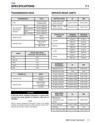
SPECIFICATIONS 4.1<br />
IGNITION<br />
Spark timing advance<br />
Idle speed<br />
Spark plug size<br />
Spark plug gap<br />
Spark plug type<br />
Ignition coil primary<br />
resistance<br />
Ignition coil <strong>se</strong>condary<br />
resistance<br />
CIRCUIT<br />
System Fu<strong>se</strong>s<br />
DATA<br />
0°-50° BTDC (range)<br />
30° BTDC@1000 RPM<br />
1000 ± 50 RPM<br />
12 mm<br />
0.038-0.043 in<br />
0.97-1.09 mm<br />
Harley-Davidson<br />
No. 6R12 (no substitute)<br />
0.5-0.7 ohms<br />
5500-7500 ohms<br />
RATING<br />
(AMPERES)<br />
COLOR<br />
Maxi-Fu<strong>se</strong> 40 Orange<br />
Headlamp 15 Blue<br />
Ignition 15 Blue<br />
Lighting 15 Blue<br />
Instruments 15 Blue<br />
Brakes/Crui<strong>se</strong> 15 Blue<br />
Radio Memory 15 Blue<br />
Radio Power 10 Red<br />
Accessory 15 Blue<br />
System Fu<strong>se</strong> Block (Under Left Side Cover)<br />
FLHR/S<br />
Battery 15 Blue<br />
P & A 15 Blue Figure 4-1. Fu<strong>se</strong> Locations<br />
11<br />
12<br />
f2210x8x<br />
10<br />
FLHT/C<br />
11<br />
f2204x8x<br />
10<br />
1<br />
1<br />
9<br />
9<br />
1. Headlamp<br />
2. Ignition<br />
3. Lighting<br />
4. Instruments<br />
5. Brakes/Crui<strong>se</strong><br />
6. Radio Memory<br />
2<br />
2<br />
8<br />
8 7<br />
6<br />
5<br />
5<br />
3<br />
3<br />
4<br />
4<br />
7. Radio Power<br />
8. Accessory<br />
9. Battery<br />
10. Brake Light Relay<br />
11. P&A<br />
12. Starter Relay<br />
2004 Touring: Engine Management (Carbureted) 4-1
HOME<br />
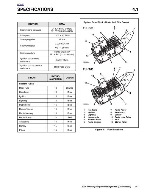
DIAGNOSTIC INTRODUCTION 4.2<br />
SYSTEM PROBLEMS<br />
All system problems fall into at least one of three general categories.<br />
No Start<br />
The engine cranks over freely, but will not start. This does not<br />
include situations where the engine will not crank, such as a<br />
bad starter, dead battery, etc. This condition assumes that all<br />
obvious <strong>check</strong>s (fuel in tank, etc.) have been made.<br />
50 60 70<br />
40<br />
80<br />
30<br />
90<br />
MPH<br />
20<br />
100<br />
10<br />
110<br />
0<br />
120<br />
10<br />
20<br />
0<br />
40<br />
30 50<br />
RPMx100<br />
Poor Performance<br />
CERTIFIED<br />
HARLEY-DAVIDSON<br />
HARLEY-DAVIDSON<br />
The engine starts but there are performance problems. The<strong>se</strong><br />
problems may include poor fuel economy, rough idle, engine<br />
misfire, engine hesitation, <strong>se</strong>vere spark knock, etc.<br />
Check Engine Lamp<br />
See Figure 4-2. The <strong>check</strong> engine lamp indicates the ignition<br />
control module (ICM) has determined a fault condition exists.<br />
There may also be starting or performance problems.<br />
Check Engine Lamp<br />
Figure 4-2. Speedometer<br />
f2160x8x<br />
RESOLVING PROBLEMS<br />
To resolve system problems, five basic steps are involved. In<br />
order of occurrence, they are:<br />
1. Check for <strong>diagnostic</strong> trouble codes (DTCs) by ob<strong>se</strong>rving<br />
<strong>check</strong> engine lamp. See 4.3 CHECKING FOR TROUBLE<br />
CODES.<br />
2. Retrieve DTCs using speedometer <strong>se</strong>lf <strong>diagnostic</strong>s. See<br />
4.5 SPEEDOMETER SELF DIAGNOSTICS.<br />
3. Diagno<strong>se</strong> system problems. This involves using special<br />
tools and the <strong>diagnostic</strong> flow charts in this <strong>se</strong>ction.<br />
4. Correct problems through the replacement and/or repair<br />
of the affected components.<br />
5. After repairs are performed, the work must be validated.<br />
This involves clearing the DTCs and confirming proper<br />
vehicle operation as indicated by the behavior of the<br />
<strong>check</strong> engine lamp.<br />
4-2 2004 Touring: Engine Management (Carbureted)
HOME<br />
CHECKING FOR TROUBLE CODES 4.3<br />
CHECK ENGINE LAMP<br />
To diagno<strong>se</strong> system problems, start by ob<strong>se</strong>rving the behavior<br />
of the <strong>check</strong> engine lamp.<br />
●<br />
●<br />
●<br />
●<br />
●<br />
NOTE<br />
See Figure 4-3. “Key ON” means that the ignition key is<br />
turned to ON and the engine stop switch is <strong>se</strong>t to RUN<br />
(although the engine is not running).<br />
When the ignition switch is turned ON, the <strong>check</strong> engine<br />
lamp will illuminate for approximately four <strong>se</strong>conds and<br />
then turn off.<br />
If the <strong>check</strong> engine lamp is not illuminated at key ON or if<br />
it fails to turn OFF after the ititial four <strong>se</strong>cond period, then<br />
<strong>se</strong>e 4.5 SPEEDOMETER SELF DIAGNOSTICS.<br />
If the <strong>check</strong> engine lamp comes on late (after 20 <strong>se</strong>conds),<br />
the problem is likely a <strong>se</strong>rial data bus failure. Test<br />
for codes using speedometer <strong>se</strong>lf <strong>diagnostic</strong>s. See 4.5<br />
SPEEDOMETER SELF DIAGNOSTICS.<br />
If the <strong>check</strong> engine lamp fails to turn OFF after the <strong>initial</strong><br />
four <strong>se</strong>cond period, then a problem exists in the instrumentation.<br />
See 4.5 SPEEDOMETER SELF DIAGNOS-<br />
TICS.<br />
1. When the lamp turns off after being illuminated for the<br />
first four <strong>se</strong>cond period, it will:<br />
a. Remain off if there are no fault conditions or trouble<br />
codes currently detected by the ignition control module.<br />
See A of Figure 4-4.<br />
b. Come back on for an 8 <strong>se</strong>cond period if only historic<br />
codes exist. See B of Figure 4-4.<br />
Figure 4-3. Ignition Switch (FLHT/C)<br />
f1240x2x<br />
c. Come back on, and remain on, if a current trouble<br />
code exists. See C of Figure 4-4.<br />
2. See CODE TYPES which follows for a complete description<br />
of trouble code formats.<br />
NOTE<br />
Trouble codes relating to the ignition coil can only be fully<br />
diagno<strong>se</strong>d during actuation. For example, a problem with the<br />
ignition coil will be considered a current fault even after the<br />
problem is corrected, since the ignition control module will not<br />
know of its resolution until after the coil is exerci<strong>se</strong>d by vehicle<br />
start <strong>se</strong>quence. In this manner, there may sometimes be a<br />
fal<strong>se</strong> indication of the current trouble code.<br />
ON<br />
OFF<br />
A<br />
Key On<br />
4 Sec.<br />
Lamp OFF: No Current or Historic Trouble Codes<br />
ON<br />
OFF<br />
B<br />
Key On<br />
4 Sec.<br />
Lamp ON 8 Seconds:<br />
Only Historic Trouble Codes Exist<br />
4 Sec.<br />
8 Sec.<br />
Lamp OFF<br />
ON<br />
OFF<br />
C<br />
Key On<br />
4 Sec.<br />
4 Sec.<br />
Lamp Remains ON: Current Trouble Code *<br />
* Historic Trouble Codes May Also Exist<br />
Figure 4-4. Check Engine Lamp Operation<br />
2004 Touring: Engine Management (Carbureted) 4-3
HOME<br />
CODE TYPES<br />
There are two types of <strong>diagnostic</strong> trouble codes (DTCs):<br />
current and historic. If a trouble code is stored, it can be read<br />
using the speedometer <strong>se</strong>lf <strong>diagnostic</strong>s. See 4.5 SPEEDOM-<br />
ETER SELF DIAGNOSTICS.<br />
RETRIEVING DIAGNOSTIC<br />
TROUBLE CODES<br />
The engine management system provides two levels of <strong>diagnostic</strong>s.<br />
All trouble codes reside in the memory of the ignition control<br />
module (ICM) until cleared using the speedometer <strong>se</strong>lf <strong>diagnostic</strong>s.<br />
See 4.5 SPEEDOMETER SELF DIAGNOSTICS.<br />
A trouble code is also cleared after a total of 50 trips has<br />
elasped. A trip consists of a start and run cycle, the run cycle<br />
lasting at least 30 <strong>se</strong>conds. After the 50 trip retention period,<br />
the trouble code is automatically era<strong>se</strong>d from memory providing<br />
that no sub<strong>se</strong>quent faults of the same type are detected in<br />
that period.<br />
●<br />
●<br />
The most sophisticated mode employs a computer<br />
ba<strong>se</strong>d <strong>diagnostic</strong> package called DIGITAL TECHNICIAN<br />
(Part No. HD-44750).<br />
The <strong>se</strong>cond mode requires using the speedometer <strong>se</strong>lf<br />
<strong>diagnostic</strong>s. Speedometer, tachometer (if equipped),<br />
TSM/TSSM and ECM codes can be acces<strong>se</strong>d and<br />
cleared. See 4.5 SPEEDOMETER SELF DIAGNOS-<br />
TICS.<br />
Current<br />
Current trouble codes are tho<strong>se</strong> which pre<strong>se</strong>ntly disrupt<br />
motorcycle operation. See the appropriate flow charts for<br />
solutions.<br />
Historic<br />
If a particular problem happens to resolve it<strong>se</strong>lf, the active<br />
status is dropped and it becomes a historic fault rather than a<br />
current fault.<br />
Historic trouble codes can only be retrieved using a computer<br />
ba<strong>se</strong>d <strong>diagnostic</strong> package called DIGITAL TECHNICIAN<br />
(Part No. HD-44750).<br />
Historic trouble codes are stored for a length of time to assist<br />
in the diagnosis of intermittent faults.<br />
MULTIPLE DIAGNOSTIC TROUBLE<br />
CODES<br />
While it is possible for more than one fault to occur and <strong>se</strong>t<br />
more than one trouble code, there are <strong>se</strong>veral conditions<br />
which may result in one fault <strong>se</strong>tting multiple trouble codes:<br />
● Serial data codes (DTC U1016, U1064, U1097, U1255,<br />
U1300 and U1301) may be accompanied by other<br />
codes. Always correct the <strong>se</strong>rial data codes before<br />
resolving the other codes.<br />
For proper resolution to multiple trouble codes refer to <strong>diagnostic</strong><br />
code priority chart (Table 4-5.)<br />
It is important to note that historic trouble codes may also be<br />
pre<strong>se</strong>nt whenever the system indicates the existence of a<br />
current fault. See MULTIPLE DIAGNOSTIC TROUBLE<br />
CODES if multiple trouble codes are found.<br />
Diagnostic charts are designed for u<strong>se</strong> with current trouble<br />
codes and as a result they frequently suggest part replacement.<br />
4-4 2004 Touring: Engine Management (Carbureted)
HOME<br />
INITIAL DIAGNOSTIC CHECK: ICM <strong>4.4</strong><br />
GENERAL<br />
To locate faulty circuits or other system problems, follow the<br />
<strong>diagnostic</strong> flow charts in this <strong>se</strong>ction. For a systematic<br />
approach, always begin with INITIAL DIAGNOSTICS which<br />
follows. Read the general information and then work your way<br />
through the flow chart box by box.<br />
Diagnostic Notes<br />
If a numbered circle appears adjacent to a flow chart box,<br />
then more information is offered in the <strong>diagnostic</strong> notes. Many<br />
<strong>diagnostic</strong> notes contain supplemental information, descriptions<br />
of various <strong>diagnostic</strong> tools or references to other parts<br />
of the manual.<br />
Circuit Diagram/Wire Harness Connector<br />
Table<br />
When working through a flow chart, refer to the illustrations,<br />
the associated circuit diagram and the wire harness connector<br />
table as necessary. The wire harness connector table for<br />
each circuit diagram identifies the connector number, description,<br />
type and general location.<br />
In order to perform most <strong>diagnostic</strong> routines, a Breakout Box<br />
and a DVOM are required. See 4.6 BREAKOUT BOX: ICM.<br />
To perform the circuit <strong>check</strong>s with any degree of efficiency, a<br />
familiarity with the various wire connectors is necessary.<br />
Reprogramming ICM<br />
Diagnostic charts frequently suggest ICM replacement. In the<br />
event an ignition control module (ICM) needs to be replaced,<br />
it must be reprogrammed using a computer ba<strong>se</strong>d <strong>diagnostic</strong><br />
package called DIGITAL TECHNICIAN (Part No. HD-44750).<br />
See your dealer. Password learn procedure must also be performed.<br />
See 3.24 PASSWORD LEARN.<br />
INITIAL DIAGNOSTICS<br />
General Information<br />
The <strong>diagnostic</strong> <strong>check</strong> is an organized approach to identifying<br />
a problem cau<strong>se</strong>d by an electronic control system malfunction.<br />
If no problems are found after completion of the <strong>diagnostic</strong><br />
<strong>check</strong>, a comparison of running parameters may be u<strong>se</strong>d<br />
to help locate intermittents and out-of-specification <strong>se</strong>nsors.<br />
See Table 4-1.<br />
Diagnostic Tips<br />
●<br />
●<br />
If Speedometer reads “BUS Er” with the ignition key<br />
turned ON (engine stop switch at RUN with the engine<br />
off), <strong>check</strong> data bus for an open or short to ground<br />
between data connector [91A] terminal 3 and ICM connector<br />
[10B] terminal 12, TSSM connector [30B] terminal<br />
3, Speedometer connector [39B] terminal 2 or tachometer<br />
(if equipped) connector [108B] terminal 2.<br />
Check for an open <strong>diagnostic</strong> test terminal between data<br />
link connector [91A] terminal 3 and TSM/TSSM connector<br />
[30B] terminal 3. With ignition key turned ON, <strong>se</strong>rial<br />
data bus voltage should be typically 0.6-0.8 volts. The<br />
range of acceptable voltage is 0-7.0 volts.<br />
Diagnostic Notes<br />
The reference numbers below correlate with the circled numbers<br />
on the <strong>diagnostic</strong> <strong>check</strong> flow charts. See page 4-10.<br />
1. Compare engine behavior to symptoms tables in this<br />
<strong>se</strong>ction.<br />
a. Starts hard. See Table 4-2.<br />
b. Hesitates, stumbles, surges, misfires and/or sluggish<br />
performance. See Table 4-3.<br />
c. Engine exhaust emits black smoke or fouls plugs.<br />
See Table 4-4.<br />
2. U<strong>se</strong> HARNESS CONNECTOR TEST KIT (Part No. HD-<br />
41404), black socket probes and patch cord.<br />
3. Connect BREAKOUT BOX (Part No. HD-42682) to ignition<br />
control module. See 4.6 BREAKOUT BOX: ICM.<br />
All <strong>diagnostic</strong> codes are listed in Table 4-5.<br />
See 3.9 INITIAL DIAGNOSTIC CHECK: TSM/TSSM for any<br />
codes related to the turn signal module (TSM) or turn signal<br />
<strong>se</strong>curity module (TSSM).<br />
See 2.5 BREAKOUT BOX: SPEEDOMETER for any codes<br />
related to the speedometer.<br />
2004 Touring: Engine Management (Carbureted) 4-5
HOME<br />
Table 4-1. Typical Running Values<br />
ITEM<br />
MAP <strong>se</strong>nsor<br />
MIN.<br />
VALUE<br />
0.1 V<br />
(high<br />
vacuum)<br />
MAX.<br />
VALUE<br />
4.96 V<br />
(atmospheric<br />
pressure)<br />
HOT<br />
IDLE<br />
1.5-3.0 V<br />
RPM 0 5600 1000<br />
Bank angle<br />
<strong>se</strong>nsor<br />
Run mode<br />
0.45-1.1 V<br />
Disable<br />
1.8-3.2 V<br />
Table 4-2. Engine Starts Hard<br />
SYMPTOM<br />
Battery discharged<br />
Spark plugs<br />
Spark plug wires<br />
Ignition coil<br />
Valve sticking<br />
Water or dirt in fuel system<br />
SOLUTION<br />
Run mode<br />
0.45-1.1 V<br />
See charging system troubleshooting<br />
in this <strong>se</strong>ction.<br />
4.12 MISFIRE.<br />
4.12 MISFIRE<br />
4.12 MISFIRE.<br />
See Section 3 in Touring Service<br />
Manual.<br />
Drain and refill with fresh fuel.<br />
Table 4-3. Engine Performance Problems<br />
Manifold leak<br />
SYMPTOM<br />
MAP <strong>se</strong>nsor plugged or not<br />
operating properly<br />
Water or dirt in fuel system<br />
Spark plugs<br />
EVAP ho<strong>se</strong> disconnected<br />
from induction module (CA)<br />
Throttle plates not opening<br />
fully<br />
SOLUTION<br />
Perform intake leak test.<br />
See 4.8 INTAKE LEAK<br />
TEST.<br />
4.13 DTC P0106, P0107,<br />
P0108<br />
Drain and refill with fresh<br />
fuel.<br />
4.12 MISFIRE.<br />
Connect.<br />
See throttle cable adjustment<br />
in Touring Service<br />
Manual.<br />
Table 4-4. Engine Exhaust Emits<br />
Black Smoke or Fouls Plugs<br />
SYMPTOM<br />
Clogged air filter<br />
SOLUTION<br />
See Section 1 in Touring<br />
Service Manual.<br />
4-6 2004 Touring: Engine Management (Carbureted)
HOME<br />
PRIORITY<br />
RANKING<br />
Table 4-5. Diagnostic Trouble Codes (DTC) and Fault Conditions<br />
DTC NO. FAULT CONDITION SOLUTION<br />
1 P0605 flash memory error 4.19 DTC P0602, P0603, P0604, P0605, P0607<br />
2 P0603 EEProm memory error 4.19 DTC P0602, P0603, P0604, P0605, P0607<br />
3 P0602 Flash memory error 4.19 DTC P0602, P0603, P0604, P0605, P0607<br />
4 P0604 RAM memory error 4.19 DTC P0602, P0603, P0604, P0605, P0607<br />
5 P0607 A to D error 4.19 DTC P0602, P0603, P0604, P0605, P0607<br />
6 “BUS Er” Serial data bus shorted low/open/high 4.10 STARTS, THEN STALLS<br />
7 U1300 <strong>se</strong>rial data shorted low 4.10 STARTS, THEN STALLS<br />
8 U1301 <strong>se</strong>rial data shorted high 4.10 STARTS, THEN STALLS<br />
9 U1064 lost TSM/TSSM communication 4.20 DTC U1064<br />
10 U1097 lost speedometer communication 4.21 DTC U1097<br />
11 U1255 Missing respon<strong>se</strong> at TSSM 4.20 DTC U1064<br />
12 U1255 Missing respon<strong>se</strong> at speedometer 4.21 DTC U1097<br />
13 P1009<br />
TSM/TSSM disabled fuel due to bad<br />
password<br />
4.15 DTC P1009, P1010<br />
14 P1010<br />
TSM/TSSM disabled fuel due to no password<br />
(starts then stalls)<br />
4.15 DTC P1009, P1010<br />
15 P0373 crankshaft position <strong>se</strong>nsor intermittent 4.17 DTC P0373, P0374<br />
16 P0374<br />
crankshaft position <strong>se</strong>nsor not detected/<br />
cannot synchronize<br />
4.17 DTC P0373, P0374<br />
17 P0106 MAP <strong>se</strong>nsor rate-of-change error 4.13 DTC P0106, P0107, P0108<br />
18 P0107 MAP <strong>se</strong>nsor failed open/low 4.13 DTC P0106, P0107, P0108<br />
19 P0108 MAP <strong>se</strong>nsor failed high 4.13 DTC P0106, P0107, P0108<br />
21 P1351 Ignition coil driver front low/open 4.16 DTC P1351, P1352, P1354, P1355<br />
20 P1354 Ignition coil driver rear low/open 4.16 DTC P1351, P1352, P1354, P1355<br />
22 P1352 Ignition coil driver front high 4.16 DTC P1351, P1352, P1354, P1355<br />
23 P1355 Ignition coil driver rear high 4.16 DTC P1351, P1352, P1354, P1355<br />
24 P0562 system voltage low 4.14 DTC P0562, P0563<br />
25 P0563 system voltage high 4.14 DTC P0562, P0563<br />
26 P0501 VSS failed low 4.18 DTC P0501, P0502<br />
27 P0502 VSS failed high/open 4.18 DTC P0501, P0502<br />
2004 Touring: Engine Management (Carbureted) 4-7
HOME<br />
f2208z8x<br />
BK<br />
LtGN/V<br />
O<br />
BN/GY<br />
[156B] [156A]<br />
6<br />
5<br />
4<br />
3<br />
2<br />
1<br />
BN/GY<br />
6<br />
5<br />
4<br />
3<br />
2<br />
1<br />
Main to Interconnect<br />
Harness<br />
LtGN/V<br />
GY<br />
1 2 3 4 5 6 7 8 9 10 11 12<br />
1 2 3 4 5 6 7 8 9 10 11 12<br />
TSM/TSSM<br />
BK<br />
[30B]<br />
[30A]<br />
1 2 3 4 5 6 7 8 9 10 11 12<br />
1 2 3 4 5 6 7 8 9 10 11 12<br />
Speedometer<br />
[39B]<br />
[39A]<br />
[108B]<br />
[108A]<br />
1 2 3 4 5 6 7 8 9 10 11 12<br />
1 2 3 4 5 6 7 8 9 10 11 12<br />
Tachometer<br />
GY<br />
1 2 3 4 5 6 7 8 9 10 11 12<br />
1 2 3 4 5 6 7 8 9 10 11 12<br />
[8B]<br />
[8A]<br />
BK<br />
Ignition<br />
Harness<br />
[2A]<br />
[2B]<br />
15A<br />
Accessory<br />
Fu<strong>se</strong><br />
1 2 3 4 5 6 7 8 9 10 11 12<br />
1 2 3 4 5 6 7 8 9 10 11 12<br />
Main to Interconnect<br />
Harness<br />
[1B] [1A]<br />
12 11 10 9 8 7 6 5 4 3 2 1<br />
12 11 10 9 8 7 6 5 4 3 2 1<br />
Main to Interconnect<br />
Harness<br />
15A<br />
Ignition<br />
Fu<strong>se</strong><br />
LtGN/V<br />
1<br />
2<br />
3<br />
4<br />
[91A]<br />
Data Link<br />
15A<br />
Battery<br />
Fu<strong>se</strong><br />
[10B]<br />
[10A]<br />
Ignition Control Module<br />
12<br />
12<br />
Serial data<br />
Figure 4-5. Diagnostic Check (FLHT/C)<br />
Table 4-6. Wire Harness Connectors in Figure 4-5.<br />
NO. DESCRIPTION TYPE LOCATION<br />
[1] Main to Interconnect Harness 12-Place Deutsch (Black) Inner Fairing - Right Radio Support Bracket<br />
[2] Main to Interconnect Harness 12-Place Deutsch (Gray) Inner Fairing - Right Fairing Support Brace<br />
[8] Ignition Harness 12-Place Deutsch Under Right Side Cover<br />
[10] Ignition Control Module 12-Place Deutsch Under Right Side Cover<br />
[30] Turn Signal/Security Module 12-Place Deutsch<br />
Cavity in Crossmember at Rear of<br />
Battery Box (Under Seat)<br />
[39] Speedometer 12-Place Packard Inner Fairing (Back of Speedometer)<br />
[91] Data Link 4-Place Deutsch Under Right Side Cover<br />
[108] Tachometer 12-Place Packard Inner Fairing (Back of Tachometer)<br />
[156] Main to Interconnect Harness 6-Place Deutsch Inner Fairing - Right Fairing Support Brace<br />
4-8 2004 Touring: Engine Management (Carbureted)
HOME<br />
f2208y8x<br />
BK<br />
GY<br />
LtGN/V<br />
LtGN/V<br />
BK<br />
BN/GY<br />
BN/GY<br />
O<br />
1 2 3 4 5 6 7 8 9 10 11 12<br />
1 2 3 4 5 6 7 8 9 10 11 12<br />
TSM/TSSM<br />
[30B]<br />
[30A]<br />
1 2 3 4 5 6 7 8 9 10 11 12<br />
1 2 3 4 5 6 7 8 9 10 11 12<br />
Speedometer<br />
[39B]<br />
[39A]<br />
GY<br />
1 2 3 4 5 6 7 8 9 10 11 12<br />
1 2 3 4 5 6 7 8 9 10 11 12<br />
BK<br />
[8B]<br />
[8A]<br />
Ignition<br />
Harness<br />
15A<br />
Battery<br />
Fu<strong>se</strong><br />
15A<br />
Accessory<br />
Fu<strong>se</strong><br />
1<br />
2<br />
3<br />
4<br />
[91A]<br />
Data Link<br />
15A<br />
Ignition<br />
Fu<strong>se</strong><br />
LtGN/V<br />
[10B]<br />
[10A]<br />
Ignition Control Module<br />
12<br />
12<br />
Serial data<br />
Figure 4-6. Diagnostic Check (FLHR/S)<br />
Table 4-7. Wire Harness Connectors in Figure 4-6.<br />
NO. DESCRIPTION TYPE LOCATION<br />
[8] Ignition Harness 12-Place Deutsch Under Right Side Cover<br />
[10] Ignition Control Module 12-Place Deutsch Under Right Side Cover<br />
[30] Turn Signal/Security Module 12-Place Deutsch<br />
Cavity in Crossmember at Rear of<br />
Battery Box (Under Seat)<br />
[39] Speedometer 12-Place Packard Under Console (Back of Speedometer)<br />
[91] Data Link 4-Place Deutsch Under Right Side Cover<br />
2004 Touring: Engine Management (Carbureted) 4-9
HOME<br />
Initial Diagnostic Check (Part 1 of 2)<br />
Does engine<br />
start?<br />
YES.<br />
Starts and<br />
runs.<br />
YES.<br />
Starts, then<br />
stalls.<br />
NO.<br />
Cranks, but<br />
will not start.<br />
NO.<br />
Engine will not<br />
crank.<br />
1<br />
Check for trouble<br />
codes. See 4.5<br />
SPEEDOMETER<br />
SELF DIAGNOSTICS<br />
Codes found?<br />
See 4.10 STARTS, THEN<br />
STALLS.<br />
See 4.9 ENGINE CRANKS,<br />
BUT WILL NOT START.<br />
See 1.2 STARTING SYSTEM<br />
DIAGNOSIS.<br />
YES<br />
NO<br />
Refer to applicable trouble code priority chart.<br />
All <strong>diagnostic</strong> codes are listed on page 4-7 in<br />
Table 4-5. Codes are listed by priority.<br />
With ignition switch OFF, press and<br />
relea<strong>se</strong> odometer re<strong>se</strong>t switch. Does<br />
odometer display appear?<br />
YES<br />
NO<br />
STOP<br />
Go to Initial Diagnostic<br />
Check (Part 2 of 2).<br />
Check for continuity to ground on terminal 7<br />
of speedometer. Wiggle harness during continuity<br />
<strong>check</strong>. Continuity pre<strong>se</strong>nt?<br />
YES<br />
NO<br />
Check for battery voltage at<br />
terminal 5 of speedometer<br />
while wiggling harness. Battery<br />
voltage continuously<br />
pre<strong>se</strong>nt?<br />
Locate and<br />
repair open.<br />
YES<br />
NO<br />
Check continuity (with ignition<br />
switch OFF) between terminals<br />
8 and 11 on breakout box. Continuity<br />
pre<strong>se</strong>nt when speedometer<br />
re<strong>se</strong>t switch is depres<strong>se</strong>d?<br />
Locate and<br />
repair open.<br />
Replace speedometer.<br />
Replace speedometer<br />
re<strong>se</strong>t switch.<br />
4-10 2004 Touring: Engine Management (Carbureted)
HOME<br />
Initial Diagnostic Check (Part 2 of 2)<br />
Continued from Initial Diagnostic<br />
Check (Part 1 of 2).Turn ignition<br />
switch ON, is odometer backlight<br />
pre<strong>se</strong>nt?<br />
YES<br />
Perform “wow” test. See 4.5 SPEEDOMETER SELF DIAGNOSTICS.<br />
The following features should be functional<br />
1) backlight should illuminate<br />
2) needle should sweep its full range of motion<br />
3) LED’s should illuminate:<br />
• <strong>check</strong> engine<br />
• battery<br />
• <strong>se</strong>curity (all models)<br />
• low fuel (EFI models)<br />
• crui<strong>se</strong> (even though not crui<strong>se</strong> equipped)<br />
NO<br />
Replace Speedometer.<br />
Are all features functional?<br />
YES<br />
NO<br />
Turn key to ACC. Is<br />
backlight pre<strong>se</strong>nt?<br />
1<br />
Check for battery voltage at<br />
terminal 1 of breakout box.<br />
Battery voltage pre<strong>se</strong>nt?<br />
YES<br />
NO<br />
YES<br />
NO<br />
No trouble found.<br />
Is problem intermittent?<br />
Check for battery voltage<br />
at terminal 6. Battery voltage<br />
pre<strong>se</strong>nt?<br />
Replace speedometer.<br />
Is instrument<br />
fu<strong>se</strong> blown?<br />
YES<br />
NO<br />
YES<br />
NO<br />
Replace speedometer.<br />
Locate and repair open on<br />
O/W wire between terminal 6<br />
and accessory fu<strong>se</strong>.<br />
Locate and repair<br />
source of fault.<br />
Replace fu<strong>se</strong>.<br />
Locate and repair open<br />
between terminal 1 and<br />
instrument fu<strong>se</strong>.<br />
YES<br />
Repeat Diagnostic<br />
Check while wiggling<br />
harnes<strong>se</strong>s.<br />
NO.<br />
Speedometer Inoperative<br />
(no vehicle speed).<br />
Remove and inspect vehicle<br />
speed <strong>se</strong>nsor. Debris<br />
pre<strong>se</strong>nt?<br />
NO.<br />
Tachometer Inoperative<br />
(no engine speed).<br />
See Test 2.4 (Part 1 of 2)<br />
under 2.4 SPEEDOMETER/<br />
TACHOMETER.<br />
YES<br />
Remove debris. Reinstall<br />
Vehicle speed <strong>se</strong>nsor.<br />
NO<br />
Check for damaged wiring/<br />
loo<strong>se</strong> connection between<br />
vehicle speed <strong>se</strong>nsor and ICM.<br />
Is wiring damage/loo<strong>se</strong><br />
connection pre<strong>se</strong>nt?<br />
YES<br />
NO<br />
Locate and repair<br />
source of fault.<br />
Replace Speedometer.<br />
2004 Touring: Engine Management (Carbureted) 4-11
HOME<br />
SPEEDOMETER SELF DIAGNOSTICS 4.5<br />
GENERAL<br />
d0715x8x<br />
The speedometer is capable of displaying and clearing<br />
speedometer, tachometer, TSM/TSSM, and ICM/ECM trouble<br />
codes (<strong>diagnostic</strong> mode).<br />
DIAGNOSTICS<br />
Diagnostic Tips<br />
●<br />
●<br />
For a quick <strong>check</strong> of speedometer function, a “wow” test<br />
can be performed. Press and hold odometer re<strong>se</strong>t switch<br />
then turn ignition switch ON. Relea<strong>se</strong> re<strong>se</strong>t switch. Background<br />
lighting should illuminate, speedometer needle<br />
should sweep its full range of motion, and indicator<br />
lamps [battery, <strong>se</strong>curity, low fuel (EFI models) <strong>check</strong><br />
engine and crui<strong>se</strong>] should illuminate. Some lamps may<br />
illuminate even though they do not apply to the vehicle.<br />
For example, the crui<strong>se</strong> lamp may illuminate even though<br />
the motorcycle may not be crui<strong>se</strong> equipped.<br />
If instrument module fails “wow” test, <strong>check</strong> for battery,<br />
ground, ignition, speedometer re<strong>se</strong>t switch and accessory<br />
to speedometer. If any feature in the speedometer is<br />
non-functional, <strong>se</strong>e 2.2 INITIAL DIAGNOSTIC CHECK:<br />
SPEEDOMETER.<br />
1<br />
2<br />
1. Crui<strong>se</strong> On/Engaged<br />
2. Check Engine<br />
3. Low Fuel<br />
3 4<br />
4. Battery<br />
5. Security<br />
Figure 4-7. Speedometer (FLHR/S)<br />
5<br />
Diagnostic Notes<br />
U<strong>se</strong> of speedometer <strong>se</strong>lf <strong>diagnostic</strong>s assumes that DIGITAL<br />
TECHNICIAN (Part No. HD-44750) is not available.<br />
The reference numbers below correlate with the circled numbers<br />
in the Speedometer Self Diagnostics (chart)<br />
1. To exit <strong>diagnostic</strong> mode, turn ignition switch OFF.<br />
2. To clear DTCs for <strong>se</strong>lected module, press speedometer<br />
re<strong>se</strong>t switch for more than 5 <strong>se</strong>conds when code is displayed.<br />
This procedure will clear all codes for <strong>se</strong>lected<br />
module.<br />
4-12 2004 Touring: Engine Management (Carbureted)
HOME<br />
Speedometer Self Diagnostics (chart)<br />
1<br />
While holding odometer re<strong>se</strong>t switch in,<br />
turn ignition switch to IGN. Make sure<br />
Run/Stop switch is in RUN position.<br />
Relea<strong>se</strong> re<strong>se</strong>t switch.<br />
Does “diag” appear?<br />
YES<br />
NO<br />
”P” flashing.<br />
To display DTCs for the<br />
ICM, press and hold<br />
re<strong>se</strong>t switch for more<br />
than 5 <strong>se</strong>conds.<br />
See 2.2 INITIAL DIAGNOSTIC<br />
CHECK: SPEEDOMETER.<br />
To choo<strong>se</strong> TSM/<br />
TSSM, press and<br />
relea<strong>se</strong> re<strong>se</strong>t switch.<br />
”S” flashing.<br />
To display DTCs for<br />
TSM/TSSM, press and<br />
hold re<strong>se</strong>t switch for<br />
more than 5 <strong>se</strong>conds.<br />
To choo<strong>se</strong> Speedometer,<br />
press and relea<strong>se</strong> re<strong>se</strong>t<br />
switch.<br />
Device<br />
respon<strong>se</strong>?<br />
NO<br />
”SP” flashing.<br />
To choo<strong>se</strong> Tachometer,<br />
press and relea<strong>se</strong> re<strong>se</strong>t<br />
switch.<br />
To display DTCs for<br />
speedometer, press and<br />
hold re<strong>se</strong>t switch for more<br />
than 5 <strong>se</strong>conds.<br />
YES<br />
“none” displayed.<br />
2<br />
DTC<br />
displayed.<br />
“no rsp” displayed.*<br />
Tachometer malfunction.<br />
See 2.4 SPEEDOMETER/<br />
TACHOMETER.<br />
* Models not equipped<br />
with a tachometer will<br />
display “no rsp” normally.<br />
”T” flashing.<br />
To display DTCs for<br />
tachometer, press and<br />
hold re<strong>se</strong>t switch for more<br />
than 5 <strong>se</strong>conds.<br />
Press and relea<strong>se</strong><br />
re<strong>se</strong>t switch. Part number<br />
of module will be<br />
displayed.<br />
Press and relea<strong>se</strong><br />
re<strong>se</strong>t switch.<br />
Are more DTCs<br />
displayed?<br />
NO<br />
To choo<strong>se</strong> ICM, press and<br />
relea<strong>se</strong> re<strong>se</strong>t switch.<br />
YES<br />
“end” displayed.<br />
To clear all DTCs for<br />
<strong>se</strong>lected module hold re<strong>se</strong>t<br />
switch for more than 5 <strong>se</strong>conds.<br />
If DTCs are not to be<br />
cleared, Press and relea<strong>se</strong><br />
re<strong>se</strong>t switch. Part number of<br />
module will be displayed.<br />
Press and relea<strong>se</strong> re<strong>se</strong>t<br />
switch again to continue to<br />
next module.<br />
Figure 4-8. Speedometer Self Diagnostics<br />
2004 Touring: Engine Management (Carbureted) 4-13
HOME<br />
BREAKOUT BOX: ICM 4.6<br />
GENERAL<br />
f2191x8x<br />
The BREAKOUT BOX (Part No. HD-42682) splices into the<br />
main harness. U<strong>se</strong>d in conjunction with a DVOM, it allows circuit<br />
diagnosis of wiring harness and connections without having<br />
to probe with sharp objects.<br />
INSTALLATION<br />
1. Remove right saddlebag and side cover.<br />
2. Depress latches on connector [10] to <strong>se</strong>parate pin and<br />
socket halves.<br />
3. Attach Breakout Box as follows:<br />
a. Mate black socket housing on Breakout Box with<br />
ICM connector [10A].<br />
b. Mate black pin housing on Breakout Box with harness<br />
connector [10B].<br />
Ignition Control Module<br />
Connector [10]<br />
Figure 4-9. Electrical Bracket (Under Right Side Cover)<br />
REMOVAL<br />
1. Remove Breakout Box as follows:<br />
a. Remove black socket housing on Breakout Box from<br />
ICM connector [10A].<br />
b. Remove black pin housing on Breakout Box from<br />
harness connector [10B].<br />
2. Mate pin and socket halves of ICM connector [10].<br />
3. Install side cover and saddlebag.<br />
f2001x8x<br />
Connect Black Side<br />
Only for Tests<br />
f1998x9x<br />
Figure 4-10. Breakout Box (Part No. HD-42682)<br />
4-14 2004 Touring: Engine Management (Carbureted)
HOME<br />
WIGGLE TEST 4.7<br />
GENERAL<br />
hd39978<br />
The wiggle test indicates the pre<strong>se</strong>nce of intermittents in a<br />
wiring harness.<br />
PROCEDURE<br />
1. See Figure 4-11. Connect DVOM (Part No. HD-39978) to<br />
wiring harness between the suspect connections. When<br />
diagnosing ignition module connections, a BREAKOUT<br />
BOX (Part No. HD-42682) may be u<strong>se</strong>d to simplify the<br />
procedure. See 4.6 BREAKOUT BOX: ICM.<br />
Figure 4-11. Fluke 78 Multimeter (DVOM)<br />
(Part No. HD-39978)<br />
2. Set DVOM to read voltage changes.<br />
3. Start motorcycle engine and run at idle.<br />
4. Shake or wiggle harness to detect intermittents. If intermittents<br />
are pre<strong>se</strong>nt, radical voltage changes will register<br />
on the DVOM.<br />
2004 Touring: Engine Management (Carbureted) 4-15
HOME<br />
INTAKE LEAK TEST 4.8<br />
GENERAL<br />
9648<br />
1WARNING<br />
Propane is an extremely flammable liquid and vapor.<br />
Vapor may cau<strong>se</strong> flash fire. Keep away from heat, sparks<br />
and flame. Keep container clo<strong>se</strong>d. U<strong>se</strong> only with adequate<br />
ventilation.<br />
1WARNING<br />
Read all directions and warnings on propane bottle. Failure<br />
to follow all directions and warnings on bottle could<br />
result in death or <strong>se</strong>rious injury.<br />
●<br />
To prevent fal<strong>se</strong> readings, keep airbox cover installed<br />
when performing test.<br />
9649<br />
Figure 4-12. Nozzle<br />
●<br />
Do not direct propane into air cleaner, fal<strong>se</strong> readings will<br />
result.<br />
1<br />
4<br />
LEAK TESTER<br />
3<br />
5<br />
Parts List<br />
●<br />
Standard 14 oz. propane cylinder.<br />
2<br />
6<br />
●<br />
●<br />
Snap-on YA7148 Propane Enrichment Kit.<br />
12 inches (304 mm) long-1/4 inch (6 mm) diameter copper<br />
tubing.<br />
Tester As<strong>se</strong>mbly<br />
1. Cut rubber ho<strong>se</strong> from kit to 18 inches (457 mm) in length.<br />
2. See Figure 4-12. Flatten one end of copper tube to form<br />
a nozzle.<br />
3. In<strong>se</strong>rt round side of copper tube into end of tubing.<br />
1. Nozzle<br />
2. Copper tube<br />
3. Ho<strong>se</strong><br />
4. Valve<br />
5. Knob<br />
6. Propane bottle<br />
Figure 4-13. Leak Tester<br />
4-16 2004 Touring: Engine Management (Carbureted)
HOME<br />
INTAKE LEAK TESTING<br />
10054<br />
1. Start engine.<br />
2. Warm engine to operating temperature.<br />
3. See Figure 4-13. Turn knob counterclockwi<strong>se</strong> to open<br />
propane bottle.<br />
1WARNING<br />
Propane is an extremely flammable liquid and vapor.<br />
Vapor may cau<strong>se</strong> flash fire. Keep away from heat, sparks<br />
and flame. Keep container clo<strong>se</strong>d. U<strong>se</strong> only with adequate<br />
ventilation.<br />
NOTE<br />
Do not direct propane stream toward front of engine. If propane<br />
enters air cleaner, a fal<strong>se</strong> reading will be obtained.<br />
Figure 4-14. Checking for Leaks<br />
4. See Figure 4-14. Aim nozzle toward possible sources of<br />
leak such as fuel injectors and intake tract.<br />
5. See Figure 4-13. Push valve opane enters source of<br />
leak.<br />
2004 Touring: Engine Management (Carbureted) 4-17
HOME<br />
ENGINE CRANKS, BUT WILL NOT START 4.9<br />
GENERAL<br />
d0273x8x<br />
If starter will not crank engine, the problem is not ignition<br />
related. Refer to SECTION 1-STARTING & CHARGING.<br />
DIAGNOSTICS<br />
Diagnostic Notes<br />
The reference numbers below correlate with the circled numbers<br />
on the Test 4.9 flow charts.<br />
Figure 4-15. Spark Tester<br />
1. Check for trouble codes. See RETRIEVING DIAGNOS-<br />
TIC TROUBLE CODES under 4.3 CHECKING FOR<br />
TROUBLE CODES.<br />
7863<br />
2. Check the condition of the battery. Perform a voltage test<br />
and recharge if below 12.60V. Check battery connections<br />
and perform load test. Replace the battery if necessary.<br />
3. Remove spark plug cable from spark plug.<br />
a. Visually <strong>check</strong> condition of plug.<br />
b. See Figure 4-15. Attach cable to SPARK TESTER<br />
(Part No. HD-26792). Clip tester to cylinder head<br />
bolt.<br />
c. While cranking engine, look for spark. Repeat procedure<br />
on other spark plug cables.<br />
NOTE<br />
Engine will not spark with both spark plugs removed. When<br />
<strong>check</strong>ing for spark, u<strong>se</strong> SPARK TESTER (Part No. HD-<br />
26792) with both plugs installed.<br />
4. U<strong>se</strong> HARNESS CONNECTOR TEST KIT (Part No. HD-<br />
41404) gray pin probes and patch cords.<br />
Figure 4-16. Ignition Coil Circuit Test<br />
7. U<strong>se</strong> HARNESS CONNECTOR TEST KIT (Part No. HD-<br />
41404), gray pin probe and patch cord.<br />
8. U<strong>se</strong> HARNESS CONNECTOR TEST KIT (Part No. HD-<br />
41404), brown socket probe and patch cord.<br />
5. See Figure 4-16. Plug IGNITION COIL CIRCUIT TEST<br />
ADAPTER (Part No. HD-44687) and FUEL INJECTOR<br />
TEST LAMP (Part No. HD-34730-2C) into Breakout Box.<br />
Note that cranking the engine with test lamp in place of<br />
the ignition coil can sometimes cau<strong>se</strong> a DTC P1351,<br />
P1352, P1354 or P1355. This condition is normal and<br />
does not by it<strong>se</strong>lf indicate a malfunction. Clear codes<br />
afterward.<br />
6. Connect BREAKOUT BOX (Part No. HD-42682). See 4.6<br />
BREAKOUT BOX: ICM.<br />
4-18 2004 Touring: Engine Management (Carbureted)
HOME<br />
Crankshaft<br />
Position<br />
Sensor<br />
1<br />
2<br />
[79A]<br />
[79B]<br />
Ignition Control Module<br />
R/BK To Ignition Switch<br />
[83B]<br />
BK<br />
9<br />
Crank Sensor (-)<br />
15 Amp<br />
Ignition Fu<strong>se</strong><br />
GY<br />
A<br />
B<br />
C<br />
Ignition<br />
Coil<br />
W<br />
\<br />
B<br />
K<br />
R<br />
Y \ BE<br />
BE \ O<br />
BK<br />
8<br />
7<br />
6<br />
5<br />
Crank Sensor (+)<br />
Rear Coil<br />
Front Coil<br />
Ground<br />
W \ BK<br />
1<br />
Key ON Power<br />
To TSM/TSSM<br />
[10B] [10A]<br />
1 2 3 4 5 6 7 8 9 10 11 12<br />
[8A]<br />
[8B]<br />
To<br />
Data Link<br />
[1B]<br />
[1A]<br />
GY<br />
1 2 3 4 5 6 7 8 9 10 11 12<br />
FLHT/C Only<br />
Ground Stud<br />
Engine Stop Switch<br />
W \ BK<br />
[22B]<br />
[22A]<br />
6-Place on FLHR/S<br />
1 2 3 4 5 6 7 8 9 10 11 12<br />
Figure 4-17. Ignition Circuit<br />
Table 4-8. Wire Harness Connectors in Figure 4-17.<br />
NO. DESCRIPTION MODEL TYPE LOCATION<br />
[1]<br />
Main to Interconnect<br />
Harness<br />
FLHT/C 12-Place Deutsch (Black) Inner Fairing - Right Radio Support Bracket<br />
[8] Ignition Harness All 12-Place Deutsch Under Right Side Cover<br />
[10] Ignition Control Module All 12-Place Deutsch (Black) Under Right Side Cover<br />
Interconnect to Right FLHT/C 12-Place Deutsch Inner Fairing- Right Fairing Support Brace<br />
[22]<br />
Handlebar Switch Controls FLHR/S 6-Place Deutsch Inside Headlamp Nacelle<br />
[83] Ignition Coil All 3-Place Packard Below Fuel Tank (Left Side)<br />
2004 Touring: Engine Management (Carbureted) 4-19
HOME<br />
Test 4.9 (Part 1 of 3)<br />
ENGINE CRANKS, BUT WILL NOT START<br />
Fresh fuel in tank?<br />
Spark plug wires firmly<br />
connected to proper coil<br />
terminals?<br />
NO<br />
Add fuel and<br />
connect spark<br />
plugs.<br />
YES<br />
1<br />
Check for trouble<br />
codes.<br />
Codes found?<br />
YES<br />
NO<br />
2<br />
Check battery connections<br />
and voltage. Is voltage<br />
above 12.60?<br />
YES<br />
NO<br />
See priority listing<br />
in Table 4-5.<br />
Does battery pass<br />
load test?<br />
Recharge battery.<br />
YES<br />
NO<br />
3<br />
Check spark plug condition,<br />
replace if fouled. Check<br />
spark at both plugs while<br />
cranking. Spark pre<strong>se</strong>nt?<br />
Replace battery.<br />
YES<br />
NO<br />
Check compression. If compression is<br />
good, <strong>check</strong> fuel system.<br />
Turn ignition ON and engine<br />
stop switch to RUN.<br />
Does <strong>check</strong> engine lamp<br />
illuminate for 4 <strong>se</strong>conds?<br />
immediately after Key ON?<br />
YES<br />
NO<br />
4<br />
Check battery voltage at<br />
Terminal B of coil connector<br />
[83B] using DVOM. Battery<br />
voltage pre<strong>se</strong>nt?<br />
See<br />
4.11 NO SPARK/NO ICM<br />
POWER.<br />
YES<br />
NO<br />
STOP<br />
Go to Test 4.9<br />
(Part 2 of 3).<br />
Locate and repair open on W/<br />
BK wire to coil.<br />
4-20 2004 Touring: Engine Management (Carbureted)
HOME<br />
Test 4.9 (Part 2 of 3)<br />
ENGINE CRANKS, BUT WILL NOT START<br />
5<br />
6<br />
Continued from Test 4.9 (Part 1 of 3).<br />
Install Breakout Box and test light for the next<br />
inspection.<br />
Front coil code: Check between<br />
Terminals 1 and 6 on Breakout Box.<br />
Rear coil code: Check between<br />
Terminals 1 and 7 on Breakout Box.<br />
Does test lamp flash when engine is cranked?<br />
YES<br />
NO<br />
Check coil connections.<br />
Connections OK?<br />
YES<br />
NO<br />
7<br />
Connect Breakout Box. Check continuity<br />
between socket A of connector [83B]<br />
and terminal 7 (BK) on Breakout Box.<br />
Measure resistance between socket C of<br />
connector [83B] and terminal 6 (BK) on<br />
Breakout Box.<br />
Is resistance less than 1.0 ohm?<br />
Test spark plug cable resistance.<br />
See 4.12 MISFIRE.<br />
Resistance OK?<br />
Repair.<br />
YES<br />
NO<br />
YES<br />
Plug wires in correct<br />
coil towers?<br />
NO<br />
Replace spark<br />
plug cables.<br />
Connect DVOM to terminals 8 and 9<br />
(BK) of connector [10] on Breakout Box<br />
and <strong>se</strong>t it for AC volts. Crank engine.<br />
Does DVOM read 1 VAC minimum?<br />
Poor connection at connector<br />
[10B] or open in<br />
harness between coil<br />
and ICM. Repair open.<br />
YES<br />
NO<br />
YES<br />
NO<br />
Replace<br />
coil.<br />
Route<br />
correctly.<br />
STOP<br />
Go to Test 4.9<br />
(Part 3 of 3).<br />
8<br />
Disconnect connector [79].<br />
Check connector for moisture<br />
and corrosion. Check wires for<br />
chafing. Connect DVOM to terminals<br />
1 and 2 of connector<br />
[79A]. Crank engine. Does<br />
DVOM read 1 VAC minimum?<br />
YES<br />
NO<br />
Check for continuity between<br />
socket 1 of connector [79B]<br />
and terminal 8 of connector<br />
[10] on Breakout Box.<br />
Continuity pre<strong>se</strong>nt?<br />
With meter still connected,<br />
<strong>check</strong> for resistance.<br />
Is resistance 600-1200 ohms?<br />
YES<br />
NO<br />
YES<br />
NO<br />
Locate and repair open on<br />
BK wire between socket 2 of<br />
connector [79B] and socket 9<br />
of connector [10B].<br />
Locate and repair open on<br />
R wire between socket 1 of connector<br />
[79B] and socket 8 of<br />
connector [10B].<br />
Remove and inspect CKP<br />
<strong>se</strong>nsor. Remove any debris on<br />
<strong>se</strong>nsor. Reinstall <strong>se</strong>nsor.<br />
Replace CKP<br />
<strong>se</strong>nsor.<br />
2004 Touring: Engine Management (Carbureted) 4-21
HOME<br />
Test 4.9 (Part 3 of 3)<br />
ENGINE CRANKS, BUT WILL NOT START<br />
Continued from Test 4.9 (Part 2 of 3).<br />
Replace ignition control module (ICM). Reprogram and<br />
perform password learn. Does vehicle start?<br />
YES<br />
NO<br />
System OK.<br />
Mechanical failure. Inspect for<br />
sprocket gear, timing chain or<br />
other mechanical failure.<br />
4-22 2004 Touring: Engine Management (Carbureted)
HOME<br />
STARTS, THEN STALLS 4.10<br />
GENERAL<br />
f2191x8x<br />
Diagnostic Trouble Codes U1300, U1301,<br />
P1009, P1010 or “BUS Er”<br />
See Figure 4-18. The typical <strong>se</strong>rial data voltage range is 0<br />
volts (inactive) to 7 volts (active). Due to the short pul<strong>se</strong>, voltages<br />
will be much lower on a DVOM. In analog mode, a<br />
DVOM reading <strong>se</strong>rial data will show continuous voltage when<br />
active, typically 0.6-0.8 volts. The range for acceptable operations<br />
is 0-7.0 volts.<br />
NOTE<br />
Problems in the fuel system or idle air control system may<br />
also create this symptom.<br />
Table 4-9. Code Description<br />
DTC<br />
DESCRIPTION<br />
Data Link<br />
Connector [91]<br />
U1300 Serial data low<br />
U1301 Serial data open/high Figure 4-18. Electrical Bracket (Under Right Side Cover)<br />
DIAGNOSTICS<br />
Diagnostic Tips<br />
●<br />
●<br />
If <strong>se</strong>rial data is shorted, the<strong>se</strong> codes will automatically<br />
trip the <strong>check</strong> engine light. The odometer will read “Bus<br />
Er” in this condition.<br />
DTCs P1009 and P1010 may accompany DTCs U1300<br />
and U1301.<br />
3. U<strong>se</strong> HARNESS CONNECTOR TEST KIT (Part No. HD-<br />
41404), black socket probes and patch cord.<br />
4. Historic code U1300 would have been <strong>se</strong>t. Clear historic<br />
codes.<br />
Diagnostic Notes<br />
The reference numbers below correlate with the circled numbers<br />
on the Test 4.10 flow charts.<br />
1. Check for trouble codes. See RETRIEVING DIAGNOS-<br />
TIC TROUBLE CODES under 4.3 CHECKING FOR<br />
TROUBLE CODES.<br />
2. Connect BREAKOUT BOX (Part No. HD-42682) as follows:<br />
a. Mate black socket housing on Breakout Box with<br />
ICM connector [10A].<br />
b. Mate black pin housing on Breakout Box with harness<br />
connector [10B].<br />
c. Mate gray socket housing on Breakout Box with<br />
TSM/TSSM connector [30A].<br />
d. Mate gray pin housing on Breakout Box with harness<br />
connector [30B].<br />
2004 Touring: Engine Management (Carbureted) 4-23
HOME<br />
f2208z8x<br />
BK<br />
LtGN/V<br />
O<br />
BN/GY<br />
[156B] [156A]<br />
6<br />
5<br />
4<br />
3<br />
2<br />
1<br />
BN/GY<br />
6<br />
5<br />
4<br />
3<br />
2<br />
1<br />
Main to Interconnect<br />
Harness<br />
LtGN/V<br />
GY<br />
1 2 3 4 5 6 7 8 9 10 11 12<br />
1 2 3 4 5 6 7 8 9 10 11 12<br />
TSM/TSSM<br />
BK<br />
[30B]<br />
[30A]<br />
1 2 3 4 5 6 7 8 9 10 11 12<br />
1 2 3 4 5 6 7 8 9 10 11 12<br />
Speedometer<br />
[39B]<br />
[39A]<br />
[108B]<br />
[108A]<br />
1 2 3 4 5 6 7 8 9 10 11 12<br />
1 2 3 4 5 6 7 8 9 10 11 12<br />
Tachometer<br />
GY<br />
1 2 3 4 5 6 7 8 9 10 11 12<br />
1 2 3 4 5 6 7 8 9 10 11 12<br />
[8B]<br />
[8A]<br />
BK<br />
Ignition<br />
Harness<br />
[2A]<br />
[2B]<br />
15A<br />
Accessory<br />
Fu<strong>se</strong><br />
1 2 3 4 5 6 7 8 9 10 11 12<br />
1 2 3 4 5 6 7 8 9 10 11 12<br />
Main to Interconnect<br />
Harness<br />
[1B] [1A]<br />
12 11 10 9 8 7 6 5 4 3 2 1<br />
12 11 10 9 8 7 6 5 4 3 2 1<br />
Main to Interconnect<br />
Harness<br />
15A<br />
Ignition<br />
Fu<strong>se</strong><br />
LtGN/V<br />
1<br />
2<br />
3<br />
4<br />
[91A]<br />
Data Link<br />
15A<br />
Battery<br />
Fu<strong>se</strong><br />
[10B]<br />
[10A]<br />
Ignition Control Module<br />
12<br />
12<br />
Serial data<br />
Figure 4-19. Serial Data Circuit (FLHT/C)<br />
Table 4-10. Wire Harness Connectors in Figure 4-19.<br />
NO. DESCRIPTION TYPE LOCATION<br />
[1] Main to Interconnect Harness 12-Place Deutsch (Black) Inner Fairing - Right Radio Support Bracket<br />
[2] Main to Interconnect Harness 12-Place Deutsch (Gray) Inner Fairing - Right Fairing Support Brace<br />
[8] Ignition Harness 12-Place Deutsch Under Right Side Cover<br />
[10] Ignition Control Module 12-Place Deutsch Under Right Side Cover<br />
[30] Turn Signal/Security Module 12-Place Deutsch<br />
Cavity in Crossmember at Rear of<br />
Battery Box (Under Seat)<br />
[39] Speedometer 12-Place Packard Inner Fairing (Back of Speedometer)<br />
[91] Data Link 4-Place Deutsch Under Right Side Cover<br />
[108] Tachometer 12-Place Packard Inner Fairing (Back of Tachometer)<br />
[156] Main to Interconnect Harness 6-Place Deutsch Inner Fairing - Right Fairing Support Brace<br />
4-24 2004 Touring: Engine Management (Carbureted)
HOME<br />
f2208y8x<br />
BK<br />
GY<br />
LtGN/V<br />
LtGN/V<br />
BK<br />
BN/GY<br />
BN/GY<br />
O<br />
1 2 3 4 5 6 7 8 9 10 11 12<br />
1 2 3 4 5 6 7 8 9 10 11 12<br />
TSM/TSSM<br />
[30B]<br />
[30A]<br />
1 2 3 4 5 6 7 8 9 10 11 12<br />
1 2 3 4 5 6 7 8 9 10 11 12<br />
Speedometer<br />
[39B]<br />
[39A]<br />
GY<br />
1 2 3 4 5 6 7 8 9 10 11 12<br />
1 2 3 4 5 6 7 8 9 10 11 12<br />
BK<br />
[8B]<br />
[8A]<br />
Ignition<br />
Harness<br />
15A<br />
Battery<br />
Fu<strong>se</strong><br />
15A<br />
Accessory<br />
Fu<strong>se</strong><br />
1<br />
2<br />
3<br />
4<br />
[91A]<br />
Data Link<br />
15A<br />
Ignition<br />
Fu<strong>se</strong><br />
LtGN/V<br />
[10B]<br />
[10A]<br />
Ignition Control Module<br />
12<br />
12<br />
Serial data<br />
Figure 4-20. Serial Data Circuit (FLHR/S)<br />
Table 4-11. Wire Harness Connectors in Figure 4-20.<br />
NO. DESCRIPTION TYPE LOCATION<br />
[8] Ignition Harness 12-Place Deutsch Under Right Side Cover<br />
[10] Ignition Control Module 12-Place Deutsch Under Right Side Cover<br />
[30] Turn Signal/Security Module 12-Place Deutsch<br />
Cavity in Crossmember at Rear of<br />
Battery Box (Under Seat)<br />
[39] Speedometer 12-Place Packard Under Console (Back of Speedometer)<br />
[91] Data Link 4-Place Deutsch Under Right Side Cover<br />
2004 Touring: Engine Management (Carbureted) 4-25
HOME<br />
Test 4.10 (Part 1 of 2)<br />
ASTARTS, THEN STALLS: DTC U1300, U1301,<br />
P1009, P1010 or “BUS Er”<br />
Is there fresh<br />
fuel in tank?<br />
1<br />
YES<br />
Check for DTCs using 4.5 SPEEDOMETER<br />
SELF DIAGNOSTICS.<br />
Any DTCs found?<br />
NO<br />
Add fuel.<br />
YES.<br />
DTC P1009,<br />
P1010 found. See<br />
4.15 DTC P1009,<br />
P1010.<br />
YES.<br />
DTC U1300 or<br />
U1301 are found.<br />
YES.<br />
BUS Er pre<strong>se</strong>nt.<br />
Speedometer will not<br />
communicate with other<br />
modules.<br />
NO.<br />
No DTCs found.<br />
Inspect intake manifold for<br />
leaks using intake leak test.<br />
See 4.8 INTAKE LEAK TEST.<br />
Are leaks pre<strong>se</strong>nt (runs longer<br />
when propane is pre<strong>se</strong>nt)?<br />
STOP<br />
Go to Test 4.10<br />
(Part 2 of 2).<br />
YES<br />
Replace intake<br />
manifold <strong>se</strong>als.<br />
NO<br />
Replace ICM.<br />
Reprogram and learn<br />
password.<br />
Clear codes using speedometer <strong>se</strong>lf <strong>diagnostic</strong>s.<br />
See 4.5 SPEEDOMETER SELF DIAGNOSTICS.<br />
Confirm proper operation with no <strong>check</strong> engine<br />
lamp.<br />
4-26 2004 Touring: Engine Management (Carbureted)
HOME<br />
Test 4.10 (Part 2 of 2)<br />
STARTS, THEN STALLS: DTC U1300, U1301, P1009,<br />
P1010 or “BUS Er”<br />
2<br />
3<br />
Continued from Test 4.10 (Part 1 of 2)<br />
Test the four data connector terminals for continuity.<br />
DIAGNOSTIC LINK<br />
CONNECTOR [91A]<br />
BREAKOUT BOX<br />
(BLACK)<br />
Terminal Wire Color Terminal<br />
1 N/A N/A<br />
2 BK 5<br />
3 Lt. GN/V 12<br />
4 GY GY terminal on left<br />
side of ignition fu<strong>se</strong><br />
Continuity pre<strong>se</strong>nt in all three circumstances?<br />
YES<br />
NO<br />
Leave ICM disconnected<br />
at connector [10]. Does<br />
speedometer display TSM/<br />
TSSM data?<br />
Inspect terminals<br />
for damage or repair<br />
opens as necessary.<br />
YES<br />
NO<br />
Replace ICM. Reprogram<br />
and learn password.<br />
4<br />
Disconnect connector [30]. Check for<br />
continuity to ground at terminal 3 of connector<br />
[91A]. Continuity to ground?<br />
YES<br />
NO<br />
Locate and repair short<br />
to ground.<br />
Check for voltage at<br />
terminal 3 of connector<br />
[91A]. Voltage pre<strong>se</strong>nt?<br />
YES<br />
NO<br />
Locate and repair short<br />
to voltage.<br />
Replace TSM/TSSM. Reprogram<br />
and learn password.<br />
System OK?<br />
YES<br />
NO<br />
System<br />
OK.<br />
Disconnect connector<br />
[39]. System OK?<br />
YES<br />
NO<br />
Replace<br />
speedometer.<br />
Replace<br />
tachometer if<br />
equipped.<br />
2004 Touring: Engine Management (Carbureted) 4-27
HOME<br />
NO SPARK/NO ICM POWER 4.11<br />
GENERAL<br />
The ignition control module turns on when power is applied to<br />
Pin 1 of [10], the black connector. The ignition control module<br />
goes through an <strong>initial</strong>ization <strong>se</strong>quence every time power is<br />
removed and re-applied to Pin 1. The only visible part of this<br />
<strong>se</strong>quence is the <strong>check</strong> engine lamp. Upon starting, the <strong>check</strong><br />
engine lamp will illuminate for 4 <strong>se</strong>conds and then (if parameters<br />
are normal) go out.<br />
DIAGNOSTICS<br />
Diagnostic Notes<br />
The reference numbers below correlate with the circled numbers<br />
on the Test 4.11 flow chart.<br />
1. See FUSES in the Touring Service Manual.<br />
2. Connect BREAKOUT BOX (Part No. HD-42682). See 4.6<br />
BREAKOUT BOX: ICM.<br />
3. U<strong>se</strong> HARNESS CONNECTOR TEST KIT (Part No. HD-<br />
4104), black pin probe and patch cord.<br />
4. Remove headlamp as<strong>se</strong>mbly on FLHR/S models or<br />
outer fairing on FLHT/C.<br />
R/BK To Ignition Switch<br />
[83B]<br />
Ignition Control Module<br />
15 Amp<br />
Ignition Fu<strong>se</strong><br />
GY<br />
A<br />
B<br />
C<br />
Ignition<br />
Coil<br />
W<br />
\<br />
B<br />
K<br />
Y \ BE<br />
BE \ O<br />
BK<br />
7<br />
6<br />
5<br />
Rear Coil<br />
Front Coil<br />
Ground<br />
W \ BK<br />
1<br />
Key ON Power<br />
To TSM/TSSM<br />
[10B] [10A]<br />
1 2 3 4 5 6 7 8 9 10 11 12<br />
[8A]<br />
[8B]<br />
To<br />
Data Link<br />
[1B]<br />
[1A]<br />
GY<br />
1 2 3 4 5 6 7 8 9 10 11 12<br />
FLHT/C Only<br />
Ground Stud<br />
Engine Stop Switch<br />
W \ BK<br />
[22B]<br />
[22A]<br />
6-Place on FLHR/S<br />
1 2 3 4 5 6 7 8 9 10 11 12<br />
Figure 4-21. Ignition Control Module Power Circuit<br />
4-28 2004 Touring: Engine Management (Carbureted)
HOME<br />
Test 4.11<br />
NO SPARK/NO ICM POWER<br />
1<br />
Check Ignition<br />
Fu<strong>se</strong>. Is Fu<strong>se</strong><br />
OK?<br />
NO<br />
Replace Fu<strong>se</strong><br />
and Find<br />
Source of Fault.<br />
2<br />
3<br />
YES<br />
Connect Breakout Box. With Ignition<br />
ON, Place Multimeter Red<br />
Wire to Terminal 1 of Connector<br />
[10] on Breakout Box, Multimeter<br />
Black Wire to Terminal 5 of Connector<br />
[10] on Breakout Box. Is<br />
Voltage 12V± 1.0V.?<br />
YES<br />
NO<br />
Replace ICM.<br />
3<br />
Check Continuity Between Terminal<br />
5 of Connector [10] on Breakout Box<br />
and Ground. Continuity Pre<strong>se</strong>nt in<br />
Both Places?<br />
NO<br />
Repair Open in BK<br />
Wire (Pin 5) to<br />
Ground.<br />
3<br />
4<br />
YES<br />
Check Continuity Between Pin<br />
4 (W/BK) of Connector [22A]<br />
and Terminal 1 of Connector<br />
[10] on Breakout Box.<br />
Is Continuity Pre<strong>se</strong>nt?<br />
3<br />
YES<br />
Check Continuity<br />
Between Sockets 4<br />
(W/BK) and 3 (GY) of<br />
Connector [22B]. With<br />
Engine Stop Switch<br />
ON, Is Continuity<br />
Pre<strong>se</strong>nt?<br />
NO<br />
Locate and Repair<br />
Open in W/BK Wire<br />
Between Connectors<br />
[22] and [10].<br />
YES<br />
Locate and Repair<br />
Open in GY Wire<br />
Between Connector<br />
[22A] and Fu<strong>se</strong> Block.<br />
NO<br />
Replace<br />
Engine Stop<br />
Switch.<br />
Table 4-12. Wire Harness Connectors in Figure 4-21.<br />
NO. DESCRIPTION MODEL TYPE LOCATION<br />
[1]<br />
Main to Interconnect<br />
Harness<br />
FLHT/C 12-Place Deutsch (Black) Inner Fairing - Right Radio Support Bracket<br />
[8] Ignition Harness All 12-Place Deutsch Under Right Side Cover<br />
[10] Ignition Control Module All 12-Place Deutsch (Black) Under Right Side Cover<br />
[22]<br />
Interconnect to Right<br />
Handlebar Switch Controls<br />
FLHT/C 12-Place Deutsch Inner Fairing- Right Fairing Support Brace<br />
FLHR/S 6-Place Deutsch Inside Headlamp Nacelle<br />
2004 Touring: Engine Management (Carbureted) 4-29
HOME<br />
MISFIRE 4.12<br />
GENERAL<br />
d0273x8x<br />
Misfire at Idle or Under Load<br />
●<br />
●<br />
Battery condition and connections may also cau<strong>se</strong> misfires.<br />
Fuel system problems may also cau<strong>se</strong> misfires. Refer to<br />
Table 4-3.<br />
DIAGNOSTICS<br />
Diagnostic Notes<br />
The reference numbers below correlate with the circled numbers<br />
on the Test 4.12 flow chart.<br />
1WARNING<br />
Any open spark around gasoline or other combustibles<br />
may result in fire or explosion. Thoroughly wipe up any<br />
spilt fuel and dispo<strong>se</strong> of rags in a suitable manner. Inadequate<br />
safety precautions could result in death or <strong>se</strong>rious<br />
injury.<br />
1. See Figure 4-22. U<strong>se</strong> the SPARK TESTER (Part No. HD-<br />
26792) to verify adequate <strong>se</strong>condary voltage (25,000<br />
volts) at the spark plug.<br />
a. Turn Ignition/Light Key Switch to IGNITION.<br />
b. Remove spark plug cable from spark plug. Visually<br />
<strong>check</strong> plug condition.<br />
c. Attach cable to SPARK TESTER. Clip tester to cylinder<br />
head bolt.<br />
d. While cranking engine, watch for spark to jump<br />
tester gap on leads.<br />
IMPORTANT NOTE<br />
Spark will not be pre<strong>se</strong>nt when cranking with both spark<br />
plugs removed. When <strong>check</strong>ing for spark, u<strong>se</strong> SPARK<br />
TESTER with both spark plugs installed and one plug<br />
wire connected to SPARK TESTER.<br />
Figure 4-22. Spark Tester<br />
c. Compare resistance values to Table 4-13. Replace<br />
cables not meeting specifications. Reinstall and<br />
repeat procedure on other spark plug cable.<br />
Table 4-13. Spark Plug Cables<br />
LOCATION LENGTH RESISTANCE<br />
Front/Rear 20.2 inch (513 mm) 4975-11960<br />
3. This test can also be performed by substituting a known<br />
good coil for one causing the no spark condition. The coil<br />
does not require full installation to be functional. Verify<br />
faulty coil by performing resistance test.<br />
4. U<strong>se</strong> HARNESS CONNECTOR TEST KIT (Part No. HD-<br />
41404), gray pin probe and patch cord to the coil connector<br />
[83B].<br />
5. Inspect for corrosion at battery terminals, maxi fu<strong>se</strong> terminals,<br />
ignition fu<strong>se</strong> terminals GY and R/BK, right handlebar<br />
switch controls connector [22], and ignition coil<br />
connector [83].<br />
e. Reinstall and repeat procedure on other spark plug<br />
cable.<br />
2. Perform spark plug cable resistance test.<br />
a. Remove spark plug cable from spark plug and ignition<br />
coil. For best results, u<strong>se</strong> a needle no<strong>se</strong> pliers<br />
for removal/installation on coil. Gently grasp cable<br />
as clo<strong>se</strong> to terminals as possible.<br />
b. Using an ohmmeter, touch probes to terminals on<br />
each end plug wire.<br />
4-30 2004 Touring: Engine Management (Carbureted)
HOME<br />
R/BK To Ignition Switch<br />
[83B]<br />
Ignition Control Module<br />
15 Amp<br />
Ignition Fu<strong>se</strong><br />
GY<br />
A<br />
B<br />
C<br />
Ignition<br />
Coil<br />
W<br />
\<br />
B<br />
K<br />
Y \ BE<br />
BE \ O<br />
BK<br />
7<br />
6<br />
5<br />
Rear Coil<br />
Front Coil<br />
Ground<br />
W \ BK<br />
1<br />
Key ON Power<br />
To TSM/TSSM<br />
[10B] [10A]<br />
1 2 3 4 5 6 7 8 9 10 11 12<br />
[8A]<br />
[8B]<br />
To<br />
Data Link<br />
[1B]<br />
[1A]<br />
GY<br />
1 2 3 4 5 6 7 8 9 10 11 12<br />
FLHT/C Only<br />
Ground Stud<br />
Engine Stop Switch<br />
W \ BK<br />
[22B]<br />
[22A]<br />
6-Place on FLHR/S<br />
1 2 3 4 5 6 7 8 9 10 11 12<br />
Figure 4-23. Ignition Coil Circuit<br />
Table 4-14. Wire Harness Connectors in Figure 4-23.<br />
NO. DESCRIPTION MODEL TYPE LOCATION<br />
[1]<br />
Main to Interconnect<br />
Harness<br />
FLHT/C 12-Place Deutsch (Black) Inner Fairing - Right Radio Support Bracket<br />
[8] Ignition Harness All 12-Place Deutsch Under Right Side Cover<br />
[10] Ignition Control Module All 12-Place Deutsch (Black) Under Right Side Cover<br />
Interconnect to Right FLHT/C 12-Place Deutsch Inner Fairing- Right Fairing Support Brace<br />
[22]<br />
Handlebar Switch Controls FLHR/S 6-Place Deutsch Inside Headlamp Nacelle<br />
[83] Ignition Coil All 3-Place Packard Below Fuel Tank (Left Side)<br />
2004 Touring: Engine Management (Carbureted) 4-31
HOME<br />
Test 4.12<br />
MISFIRE AT IDLE OR UNDER LOAD<br />
Is fuel contaminated?<br />
YES<br />
NO<br />
Drain and flush<br />
tank. Refill with<br />
fresh fuel.<br />
Remove air cleaner cover. Start engine.<br />
Open throttle quickly. Does slide move up<br />
and down with throttle opening?<br />
YES<br />
Inspect intake manifold for leaks.<br />
See 4.8 INTAKE LEAK TEST.<br />
Leaks pre<strong>se</strong>nt?<br />
NO<br />
Inspect CV carburetor diaphragm<br />
for leaks. Replace<br />
or repair as necessary.<br />
YES<br />
NO<br />
Replace<br />
intake <strong>se</strong>als.<br />
1<br />
Turn Ignition Switch OFF.<br />
Disconnect one spark plug lead at a time<br />
and install Spark Tester (HD-26792). See<br />
Figure 4-22.<br />
Crank engine to induce spark. Ob<strong>se</strong>rve<br />
spark tester during test.<br />
Spark should jump tester lead gap during<br />
test. Did it?<br />
YES<br />
NO<br />
Check for:<br />
• Faulty, worn or cracked spark plug(s).<br />
• Plug fouling due to engine<br />
mechanical fault.<br />
• Faulty or poor connection at plug.<br />
2<br />
Check resistance of each spark plug<br />
cable that did not fire the spark tester.<br />
Also, <strong>check</strong> for faulty plug wire connections.<br />
Are wires OK?<br />
YES<br />
NO<br />
3<br />
Switch coil with unit<br />
known to be good.<br />
Perform spark test.<br />
Did spark jump gap<br />
during engine cranking?<br />
Replace<br />
faulty wires.<br />
YES<br />
Original ignition coil<br />
is faulty. Replace.<br />
4<br />
5<br />
NO<br />
Remove test coil. Disconnect negative battery<br />
cable. Measure resistance between battery<br />
positive and coil connector [83B]<br />
Terminal B (W/BK). Wiggle harness. Is resistance<br />
continuously less than 1.0 ohm?<br />
Clear codes using speedometer <strong>se</strong>lf <strong>diagnostic</strong>s.<br />
See 4.5 SPEEDOMETER SELF DIAGNOSTICS.<br />
Confirm proper operation with no <strong>check</strong> engine<br />
lamp.<br />
YES<br />
Replace ignition control<br />
module. Reprogram and<br />
learn password.<br />
NO<br />
Find source of<br />
intermittent and repair.<br />
4-32 2004 Touring: Engine Management (Carbureted)