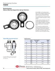
MCS2000-PSDRV2 Power Supply/Dual Voltage/Dual Channel Driver
MCS2000-PSDRV2 Power Supply/Dual Voltage/Dual Channel Driver
MCS2000-PSDRV2 Power Supply/Dual Voltage/Dual Channel Driver

You also want an ePaper? Increase the reach of your titles
YUMPU automatically turns print PDFs into web optimized ePapers that Google loves.
DIST. AUTORIZADO<br />
®<br />
MEX (55) 53 63 23 31<br />
QRO (442) 1 95 72 60<br />
MTY (81) 83 54 10 18<br />
ventas@industrialmagza.com<br />
❏ 5.<br />
Adjust the anti-residual output for <strong>Channel</strong><br />
“B” as follows if a brake is used on this<br />
output. If no brake is used, then disregard<br />
this portion of the start-up. Proceed to<br />
step 6.<br />
❏ 5a. Using a digital DC Voltmeter,<br />
connect the positive lead to<br />
terminal 3 and the negative lead to<br />
terminal 4 of the <strong>MCS2000</strong>-<br />
<strong>PSDRV2</strong> for <strong>Channel</strong> “B” input.<br />
❏ 5b. Adjust the Tension controller being<br />
used to give a 0 VDC reading on<br />
the <strong>Channel</strong> “B” input.<br />
❏ 5c. Using a small screwdriver, rotate<br />
the anti-residual potentiometer “B”<br />
fully counter-clockwise so the<br />
output voltage to the brake is zero<br />
level. <strong>Voltage</strong> can be measured to<br />
the <strong>Channel</strong> “B” brake on terminals<br />
7 and 8 of the <strong>MCS2000</strong>-<strong>PSDRV2</strong>.<br />
Terminal 7 is positive, and terminal<br />
8 is negative. Note that the<br />
“GREEN” LED for <strong>Channel</strong> “B” is<br />
flashing at this time.<br />
❏ 5d. Now slowly adjust the anti-residual<br />
potentiometer “B” clockwise while<br />
feeling the reaction on the brake.<br />
When the optimum anti-residual<br />
output is obtained, the brake will be<br />
very free to rotate or the armatures,<br />
in the case of the TB’s, will feel like<br />
they are floating away from the<br />
magnet assembly.<br />
Note: Using a meter across the brake “B”<br />
terminals 7 and 8 as noted in 5c above,<br />
the voltage observed should be negative<br />
at this time.<br />
❏ 5e. Once this point is found, do not<br />
adjust this potentiometer further or<br />
the brake can re-engage.<br />
❏ 5f.<br />
This completes the adjustment for<br />
the <strong>Channel</strong> “B” anti-residual.<br />
Proceed to step 6.<br />
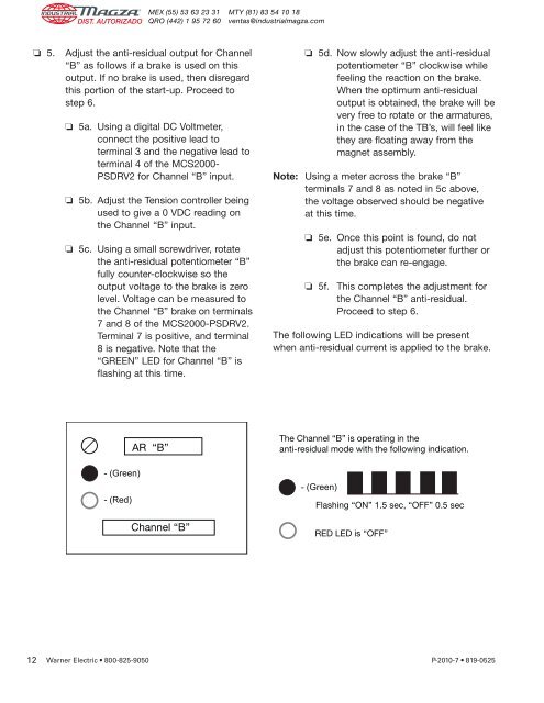
The following LED indications will be present<br />
when anti-residual current is applied to the brake.<br />
AR “B”<br />
The <strong>Channel</strong> “B” is operating in the<br />
anti-residual mode with the following indication.<br />
- (Green)<br />
- (Red)<br />
<strong>Channel</strong> “B”<br />
- (Green)<br />
Flashing “ON” 1.5 sec, “OFF” 0.5 sec<br />
RED LED is “OFF”<br />
12 Warner Electric • 800-825-9050 P-2010-7 • 819-0525