MCS2000-PSDRV2 Power Supply/Dual Voltage/Dual Channel Driver
MCS2000-PSDRV2 Power Supply/Dual Voltage/Dual Channel Driver
MCS2000-PSDRV2 Power Supply/Dual Voltage/Dual Channel Driver

You also want an ePaper? Increase the reach of your titles
YUMPU automatically turns print PDFs into web optimized ePapers that Google loves.
DIST. AUTORIZADO<br />
®<br />
MEX (55) 53 63 23 31<br />
QRO (442) 1 95 72 60<br />
MTY (81) 83 54 10 18<br />
ventas@industrialmagza.com<br />
System Troubleshooting<br />
Troubleshooting the <strong>MCS2000</strong>-<strong>PSDRV2</strong> <strong>Dual</strong><br />
<strong>Channel</strong>/<strong>Dual</strong> <strong>Voltage</strong> <strong>Driver</strong> is fairly straight<br />
forward. There are certain basic checks that can<br />
be made using a digital meter. All readings taken<br />
on the <strong>MCS2000</strong>-<strong>PSDRV2</strong> will be either DC<br />
voltages or DC currents, or AC line voltage. A<br />
meter sufficient to measure up to 100 VDC and<br />
10 Amps DC and 300 VAC will be suitable for<br />
taking any of the measurements deemed<br />
necessary.<br />
As with any electronic device, care should be<br />
taken when installing, wiring and commissioning<br />
the unit. Failure to do so may damage or destroy<br />
the driver and void the warranty.<br />
The following diagnostic indications are possible<br />
with the two indicator LED’s on the face of the<br />
controller.<br />
Additionally, the <strong>MCS2000</strong>-<strong>PSDRV2</strong> offers a<br />
certain amount of diagnostics built into the<br />
unit via the “GREEN” and “RED” LED’s for<br />
troubleshooting purposes.<br />
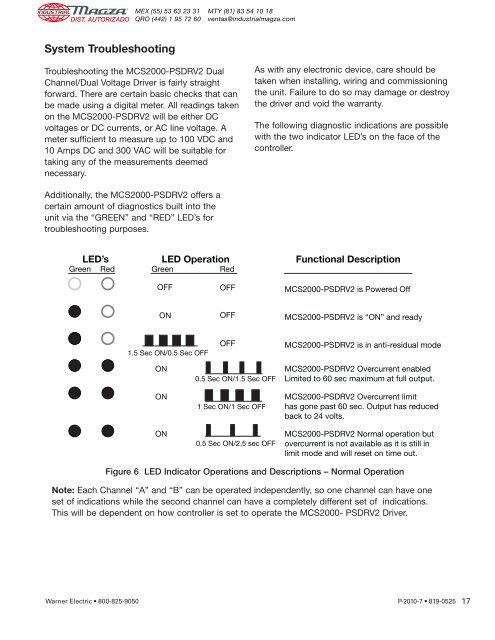
LED’s<br />
Green Red<br />
LED Operation<br />
Green<br />
Red<br />
Functional Description<br />
OFF<br />
OFF<br />
<strong>MCS2000</strong>-<strong>PSDRV2</strong> is <strong>Power</strong>ed Off<br />
ON<br />
OFF<br />
<strong>MCS2000</strong>-<strong>PSDRV2</strong> is “ON” and ready<br />
1.5 Sec ON/0.5 Sec OFF<br />
OFF<br />
<strong>MCS2000</strong>-<strong>PSDRV2</strong> is in anti-residual mode<br />
ON<br />
ON<br />
ON<br />
0.5 Sec ON/1.5 Sec OFF<br />
1 Sec ON/1 Sec OFF<br />
0.5 Sec ON/2.5 sec OFF<br />
<strong>MCS2000</strong>-<strong>PSDRV2</strong> Overcurrent enabled<br />
Limited to 60 sec maximum at full output.<br />
<strong>MCS2000</strong>-<strong>PSDRV2</strong> Overcurrent limit<br />
has gone past 60 sec. Output has reduced<br />
back to 24 volts.<br />
<strong>MCS2000</strong>-<strong>PSDRV2</strong> Normal operation but<br />
overcurrent is not available as it is still in<br />
limit mode and will reset on time out.<br />
Figure 6 LED Indicator Operations and Descriptions – Normal Operation<br />
Note: Each <strong>Channel</strong> “A” and “B” can be operated independently, so one channel can have one<br />
set of indications while the second channel can have a completely different set of indications.<br />
This will be dependent on how controller is set to operate the <strong>MCS2000</strong>- <strong>PSDRV2</strong> <strong>Driver</strong>.<br />
Warner Electric • 800-825-9050 P-2010-7 • 819-0525<br />
17