MCS2000-PSDRV2 Power Supply/Dual Voltage/Dual Channel Driver
MCS2000-PSDRV2 Power Supply/Dual Voltage/Dual Channel Driver
MCS2000-PSDRV2 Power Supply/Dual Voltage/Dual Channel Driver

Create successful ePaper yourself
Turn your PDF publications into a flip-book with our unique Google optimized e-Paper software.
DIST. AUTORIZADO<br />
®<br />
MEX (55) 53 63 23 31<br />
QRO (442) 1 95 72 60<br />
MTY (81) 83 54 10 18<br />
ventas@industrialmagza.com<br />
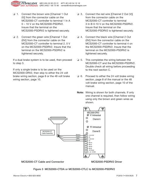
❏ 1.<br />
Connect the brown wire [<strong>Channel</strong> 1 Out<br />
(V)] from the connector cable on the<br />
<strong>MCS2000</strong>-CT controller to terminal 1 In A<br />
0 – 10 V on the <strong>MCS2000</strong>-<strong>PSDRV2</strong>.<br />
Insure that the terminal on the<br />
<strong>MCS2000</strong>-<strong>PSDRV2</strong> is tightened securely.<br />
❏ 3.<br />
Connect the red wire [<strong>Channel</strong> 2 Out (V)]<br />
from the connector cable on the<br />
<strong>MCS2000</strong>-CT controller to terminal<br />
3 In B 0-10 V on the <strong>MCS2000</strong>-<strong>PSDRV2</strong>.<br />
Insure that the terminal on the<br />
<strong>MCS2000</strong>-<strong>PSDRV2</strong> is tightened securely.<br />
❏ 2.<br />
Connect the green wire [<strong>Channel</strong> 1 Out<br />
(0V)] from the connector cable on the<br />
<strong>MCS2000</strong>-CT controller to terminal 2, 0 V<br />
on the <strong>MCS2000</strong>-<strong>PSDRV2</strong>. Insure that the<br />
terminal on the <strong>MCS2000</strong>-<strong>PSDRV2</strong> is<br />
tightened securely.<br />
❏ 4.<br />
Connect the black wire [<strong>Channel</strong> 2 Out<br />
(0V)] from the connector cable on the<br />
<strong>MCS2000</strong>-CT controller to terminal 4 on<br />
the <strong>MCS2000</strong>-<strong>PSDRV2</strong>. Insure that the<br />
terminal on the <strong>MCS2000</strong>-<strong>PSDRV2</strong> is<br />
tightened securely.<br />
If a dual brake system is to be used, then proceed<br />
to step 3.<br />
If only a single brake is to be used on the<br />
<strong>MCS2000</strong>-DRV2, then skip to either the 24 volt<br />
brake wiring section, page 8 or the 48 volt brake<br />
wiring section, page 10.<br />
❏ 5.<br />
❏ 6.<br />
This completes the wiring between the<br />
<strong>MCS2000</strong>-CT and the <strong>MCS2000</strong>-<strong>PSDRV2</strong>.<br />
Double check all wiring before proceeding<br />
to the next section C.<br />
Proceed to either the 24 volt brake wiring<br />
section, page 8 of the manual or the 48<br />
volt brake wiring section, page 10 of the<br />
manual.<br />
Note: Wiring is shown for both channels. If only<br />
one channel is required, then follow wiring<br />
using only the brown and green wires as<br />
shown.<br />
MSC2000-DRV2<br />
“A” Antiresidual<br />
<strong>Channel</strong> A<br />
“B” Antiresidual<br />
<strong>MCS2000</strong>-CT<br />
Cable Assembly<br />
(Brown)<br />
(Green)<br />
(Red)<br />
(Black)<br />
<strong>Channel</strong> B<br />
1. In A 0-10V<br />
2. 0V<br />
3. In B 0-10V<br />
4. 0V<br />
5. Brk A+<br />
6. Brk A-<br />
7. Brk B+<br />
8. Brk B-<br />
9. -DC <strong>Power</strong><br />
10. + 24 - 48 VDC<br />
<strong>MCS2000</strong>-CT Cable and Connector<br />
<strong>MCS2000</strong>-<strong>PSDRV2</strong> <strong>Driver</strong><br />
Figure 3 <strong>MCS2000</strong>-CTDA or <strong>MCS2000</strong>-CTLC to <strong>MCS2000</strong>-<strong>PSDRV2</strong><br />
Warner Electric • 800-825-9050 P-2010-7 • 819-0525<br />
7