LOCKING LINE catalogue - Kendrion Binder
LOCKING LINE catalogue - Kendrion Binder
LOCKING LINE catalogue - Kendrion Binder

Create successful ePaper yourself
Turn your PDF publications into a flip-book with our unique Google optimized e-Paper software.
BINDER<br />
secure<br />
kec<br />
group<br />
maintenance-free reliable reliable<br />
locking<br />
unlocking<br />
with sensor<br />
with emergency manual operation<br />
universal<br />
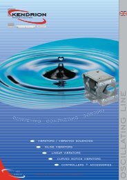
power of partnership and magnetism<br />
locking line
about us<br />
The KENDRION ELECTROMAGNETIC COMPONENTS Group<br />
(KEC Group) sees itself as a centre of excellence in the field<br />
of electromagnetism.<br />
KENDRION MAGNETTECHNIK GmbH develops and<br />
manufactures a wide range of electromagnetic products in<br />
the most diverse variations and designs for countless<br />
technical applications. The company grew out of the<br />
traditional operations of <strong>Binder</strong>, Thoma and Neue Hahn<br />
and is now Europe’s leading manufacturer of electromagnetic<br />
components.<br />
Our many years of experience in the development and<br />
manufacture of electromagnetic devices plus the skills and<br />
commitment of our employees enable us to recognise the<br />
needs of the market. And we turn those needs into highquality<br />
products in cooperation with our customers.<br />
We at KENDRION MAGNETTECHNIK achieve customerfocused<br />
solutions in all corporate divisions. Those solutions<br />
bring maximum benefits for customers and hence<br />
considerably strengthen their position in their markets.<br />
Project work is our focal point. We at KENDRION<br />
MAGNETTECHNIK take this to mean the joint development<br />
of devices together with our customers, taking into<br />
account special operating conditions, special requirements<br />
and high economic efficiency. Our objective is to provide<br />
the market with the devices it needs. With optimised costsbenefits<br />
ratios to secure the competitiveness of our<br />
customers.<br />
• Customer-centred market management,<br />
• innovative product developments,<br />
• lean, flexible logistics,<br />
• high quality standards,<br />
• affordable prices,<br />
• and the power of magnetism<br />
guarantee the success of<br />
KENDRION MAGNETTECHNIK.<br />
kendrion magnettechnik<br />
-<br />
your one-stop solution<br />
2<br />
www.kendrionmt.com
locking line<br />
Types<br />
Type LLV040002 / EMV 4002<br />
Type LLV050058 / EMV 5058<br />
Type LLV050060 / EMV 5060<br />
Type LLV050070 / EMV 5070<br />
Type LLV050080 / EMV 5080<br />
Type LLV050081 / EMV 5081<br />
Type LLV050215 / 1721503A<br />
Type LLV080215 / 1722504A<br />
Type LLV060076 / EMV 6076<br />
Functions Applications Page<br />
- locking with spring force<br />
- unlocking with magnetic force<br />
- 2-way switching status monitoring<br />
- class of protection IP 40<br />
- 8 mm stroke<br />
- safety devices<br />
- general engineering<br />
- general use in dry conditions<br />
- electrical connection via round connector<br />
- de-energised locking<br />
- locking units<br />
- 2-way switching status monitoring<br />
- materials flow controls<br />
- shut-off function<br />
- automated systems<br />
- stopper function<br />
- general machinery and apparatus<br />
- 10 mm stroke 5<br />
- locking with magnetic force<br />
- de-energised unlocking<br />
- 2-way switching status monitoring<br />
- class of protection IP 64<br />
- locking with magnetic force<br />
- de-energised unlocking<br />
- separate 1-way signal connection with plug to<br />
DIN EN 175301-803 (DIN 43650)<br />
- electromagnetic locking units for safety devices in<br />
automated systems and general engineering<br />
- electromagnetic locking units<br />
- general engineering<br />
- with GL plug for AC connection<br />
- 10 mm stroke 6+7<br />
- de-energised locking<br />
- electromagnetic locking units for machines and<br />
- unlocking with magnetic force<br />
automatic systems<br />
- 2-way switching status monitoring<br />
- with emergency manual operation<br />
- manual unlocking<br />
- general engineering<br />
- 10 mm stroke 8<br />
- de-energised locking<br />
- electromagnetic locking units for general<br />
- unlocking with magnetic force<br />
engineering<br />
- 1-way switching status monitoring with plug<br />
- with GL plug for AC connection<br />
- separate cable connections<br />
- 10 mm stroke 9<br />
- de-energised locking<br />
- electromagnetic door and window locks<br />
- signalling “open”<br />
- with pin signalling and acknowledgement signal<br />
- acknowledgement signal “locked”<br />
- general use in dry conditions<br />
- with reed contact<br />
- 15 mm stroke 10<br />
- de-energised unlocking<br />
- security element for doors and gates<br />
- magnetic locking<br />
- property security<br />
- de-energised locking<br />
- air-conditioning and ventilation systems<br />
- magnetic unlocking<br />
- 12 mm stroke 11<br />
- magnetic unlocking<br />
- locking units for safety devices with emergency<br />
- de-energised locking<br />
manual operation<br />
- class of protection IP 64<br />
- general machinery and apparatus<br />
- with emergency manual operation<br />
- 15 mm stroke 12<br />
4<br />
General instructions and accessories, plugs, sensors and strikes<br />
13-15<br />
www.kendrionmt.com 3
locking solenoids<br />
Type LLV040002/EMV 4002<br />
deep<br />
Fixings<br />
Accessories<br />
plug<br />
bellows<br />
We reserve the right to make changes<br />
to the product design.<br />
Please note ordering data!<br />
LLV040002 / EMV 4002<br />
Example of order<br />
LLV040002/EMV 4002<br />
24 VDC, 100% duty cycle<br />
de-energised locking<br />
Technical specification<br />
Insulation class F to<br />
DIN VDE 0580 (July 2000)<br />
100% duty cycle<br />
Class of protection to IEC 60529: IP 40<br />
Parameters specific to product<br />
starting force/locking bolt F S = 5 N<br />
holding force/locking bolt F H = 17 N<br />
restoring force/locking bolt F R = 10 N<br />
response time<br />
t 1 = 45 ms<br />
release time<br />
t 2 = 30 ms<br />
radial force/stationary 1200 N<br />
Circuit diagram and pin assignment at plug<br />
(solenoid de-energised)<br />
Locking solenoid<br />
type LLV040002/EMV 4002<br />
This is an electromagnetic locking unit specially designed<br />
for use in all kinds of safety devices on machines and<br />
automatic systems. During its development special<br />
attention was given to ensuring a compact design,<br />
universal fixing options and an integral acknowledgement<br />
signal for the locking function. These devices comply<br />
fully with the requirements of Germany’s Accident<br />
Prevention Regulations – and with a large factor of<br />
safety. The solenoid plunger and locking bolt are<br />
guided separately in highly wear-resistant, maintenancefree<br />
bearings. To avoid stray magnetic fields in the<br />
object to be locked, the locking bolt is made from rustproof,<br />
non-magnetic stainless steel. The microswitches<br />
integrated into the aluminium housing for the locking<br />
bolt signal the respective position of the locking bolt<br />
approx. 0.5-1 mm after it leaves the initial position or<br />
before it reaches the end position. The locking<br />
function, i.e. the extending of the locking bolt into the<br />
locked position, is achieved by means of an integral<br />
spring. The unlocking function, i.e. the retracting of<br />
the locking bolt, on the other hand, is achieved by<br />
applying an electromagnetic force.<br />
In order to achieve a quick and reliable electrical<br />
connection, a common integral plug with screw fastener<br />
to DIN 43651 is used for the linear solenoid<br />
and the acknowledgement signal.<br />
When operating the locking units with voltages exceeding<br />
48 VDC, the linear solenoid is connected via<br />
an additional device connector (to DIN EN 175301-803<br />
– DIN 43650) mounted on the solenoid housing.<br />
The magnetic forces given are reached at operating<br />
temperature and 90% of the rated voltage according<br />
to DIN VDE 0580 (July 2000), and are valid for a 24<br />
VDC supply voltage. When operating at 100% rated<br />
voltage, the magnetic forces increase by approx. 20%.<br />
Different supply voltages may lead to magnetic forces<br />
higher or lower than the specified values owing to the<br />
changing copper factor. The release times are based on<br />
switching on the DC side. With a rectifier in series and<br />
switching on the AC side, the release times are 2 to 3<br />
times higher.<br />
Device connectors are not included in the scope of<br />
supply and must be ordered separately.<br />
Surface finish: solenoid galvanised<br />
Locking bolt housing: aluminium<br />
Special versions on request.<br />
Size<br />
Function<br />
(de-energised)<br />
Stroke<br />
[mm]<br />
Power<br />
[Watt]<br />
Locking bolt<br />
Ø [mm]<br />
Sensor<br />
H A<br />
H E<br />
Weight<br />
[kg]<br />
LLV040002<br />
locked<br />
8<br />
12.8<br />
10<br />
x<br />
x<br />
0.6<br />
4 www.kendrionmt.com
locking solenoids<br />
Type LLV050058/EMV 5058<br />
Fixings<br />
deep<br />
LLV050058 / EMV5058<br />
Locking solenoid<br />
type LLV050058<br />
This is an electromagnetic locking unit specially designed<br />
for use in all kinds of safety devices on machines and<br />
automatic systems. During its development special<br />
attention was given to ensuring a compact design,<br />
universal fixing options and an integral acknowledgement<br />
signal for the locking function. These devices comply<br />
fully with the requirements of Germany’s Accident<br />
Prevention Regulations – and with a large factor of<br />
safety. The solenoid plunger and locking bolt are<br />
guided separately in highly wear-resistant, maintenancefree<br />
bearings. The integral microswitch signals the<br />
respective position of the locking bolt approx.<br />
0.5-1 mm after it leaves the initial position or before<br />
it reaches the end position. The locking function, i.e.<br />
the extending of the locking bolt into the locked position,<br />
is achieved by means of an integral spring. The<br />
unlocking function, i.e. the retracting of the locking<br />
bolt, on the other hand, is achieved by applying an<br />
electromagnetic force.<br />
In order to guarantee a trouble-free and reliable<br />
electrical connection, a common integral DIN 43651<br />
plug is used for the linear solenoid and the<br />
acknowledgement signal.<br />
When operating the locking units with voltages<br />
exceeding 48 VDC, the linear solenoid is connected via<br />
an additional device connector (to DIN EN 175301-803<br />
– DIN 43650) mounted on the solenoid housing.<br />
The magnetic forces given are reliably reached at<br />
operating temperature and 90% of the rated voltage<br />
according to DIN VDE 0580 (July 2000), and are valid<br />
for a 24 VDC supply voltage. When operating at 100%<br />
rated voltage, the magnetic forces increase by approx.<br />
20%. Different supply voltages may lead to magnetic<br />
forces higher or lower than the specified values owing<br />
to the changing copper factor. The release times are<br />
based on switching on the DC side. With a rectifier in<br />
series and switching on the AC side, the release times<br />
are 2 to 3 times higher.<br />
Device connectors are not included in the scope of<br />
supply and must be ordered separately.<br />
Surface finish: solenoid galvanised<br />
Locking bolt housing: aluminium<br />
Special versions on request.<br />
Accessories<br />
round plug<br />
bellows<br />
We reserve the right to make changes<br />
to the product design.<br />
Please note ordering data!<br />
Example of order<br />
LLV050058/EMV 5058<br />
24 VDC, 100% duty cycle<br />
de-energised unlocking<br />
Technical specification<br />
Insulation class F to<br />
DIN VDE 0580 (July 2000)<br />
100% duty cycle<br />
Class of protection to IEC 60529: IP 64<br />
Parameters specific to product<br />
starting force/locking bolt F S = 7 N<br />
holding force/locking bolt F H = 35 N<br />
restoring force/locking bolt F R = 20 N<br />
response time<br />
t 1 = 120 ms<br />
release time<br />
t 2 = 100 ms<br />
radial force/stationary 3000 N<br />
Circuit diagram and pin assignment at plug<br />
(solenoid de-energised)<br />
Size<br />
Function<br />
(de-energised)<br />
Stroke<br />
[mm]<br />
Power<br />
[Watt]<br />
Locking bolt<br />
Ø [mm]<br />
Sensor<br />
H A<br />
H E<br />
Weight<br />
[kg]<br />
LLV050058<br />
locked<br />
10<br />
18.5<br />
14<br />
x<br />
x<br />
1.25<br />
www.kendrionmt.com<br />
5
locking solenoids<br />
Type LLV050060/EMV 5060<br />
Fixings<br />
deep<br />
Accessories<br />
plug<br />
bellows<br />
We reserve the right to make changes<br />
to the product design.<br />
Please note ordering data!<br />
LLV050060 / EMV 5060<br />
Example of order<br />
LLV050060/EMV 5060<br />
24 VDC, 100% duty cycle<br />
de-energised locking<br />
Technical specification<br />
Insulation class F to<br />
DIN VDE 0580 (July 2000)<br />
100% duty cycle<br />
Class of protection to IEC 60529: IP 64<br />
Parameters specific to product<br />
starting force/locking bolt F S = 7 N<br />
holding force/locking bolt F H = 35 N<br />
restoring force/locking bolt F R = 20 N<br />
response time<br />
t 1 = 120 ms<br />
release time<br />
t 2 = 100 ms<br />
radial force/stationary 3000 N<br />
Circuit diagram and pin assignment at plug<br />
(solenoid de-energised)<br />
Locking solenoid<br />
type LLV050060/EMV 5060<br />
This is an electromagnetic locking unit specially designed<br />
for use in all kinds of safety devices on machines and<br />
automatic systems. During its development special<br />
attention was given to ensuring a compact design,<br />
universal fixing options and an integral acknowledgement<br />
signal for the locking function. These devices comply<br />
fully with the requirements of Germany’s Accident<br />
Prevention Regulations – and with a large factor of<br />
safety. The solenoid plunger and locking bolt are<br />
guided separately in highly wear-resistant, maintenancefree<br />
bearings. The integral microswitches signal the<br />
respective position of the locking bolt approx.<br />
0.5-1 mm after it leaves the initial position or before<br />
it reaches the end position. The return movement of<br />
the locking bolt into the locked position is achieved by<br />
means of an integral spring.<br />
In order to achieve a quick and reliable electrical<br />
connection, a common integral DIN 43651 plug is used<br />
for the linear solenoid and the acknowledgement<br />
signal.<br />
When operating the locking units with voltages<br />
exceeding 48 VDC, the linear solenoid is connected via<br />
an additional device connector (to DIN EN 175301-803<br />
– DIN 43650) mounted on the solenoid housing.<br />
The magnetic forces given are reached at operating<br />
temperature and 90% of the rated voltage according<br />
to DIN VDE 0580 (July 2000), and are valid for a<br />
24 VDC supply voltage. When operating at 100% rated<br />
voltage, the magnetic forces increase by approx. 20%.<br />
Different supply voltages may lead to magnetic forces<br />
higher or lower than the specified values owing to the<br />
changing copper factor. The release times are based on<br />
switching on the DC side. With a rectifier in series and<br />
switching on the AC side, the release times are 2 to 3<br />
times higher.<br />
Device connectors are not included in the scope of<br />
supply and must be ordered separately.<br />
Surface finish: solenoid galvanised<br />
Locking bolt housing: aluminium<br />
Special versions on request.<br />
Size<br />
Function<br />
(de-energised)<br />
Stroke<br />
[mm]<br />
Power<br />
[Watt]<br />
Locking bolt<br />
Ø [mm]<br />
Sensor<br />
H A<br />
H E<br />
Weight<br />
[kg]<br />
LLV050060<br />
unlocked<br />
10<br />
18.5<br />
14<br />
x<br />
x<br />
1.4<br />
6 www.kendrionmt.com
locking solenoids<br />
Fixings<br />
Type LLV050070/EMV 5070<br />
deep<br />
can be rotated through 4 x 90°<br />
LLV050070 / EMV5070<br />
Locking solenoid<br />
type LLV050070/EMV 5070<br />
This is an electromagnetic locking unit specially designed<br />
for use in all kinds of safety devices on machines and<br />
automatic systems. During its development special<br />
attention was given to ensuring a compact design,<br />
universal fixing options and an integral acknowledgement<br />
signal for the locking function. These devices comply<br />
fully with the requirements of Germany’s Accident<br />
Prevention Regulations – and with a large factor of<br />
safety. The solenoid plunger and locking bolt are<br />
guided separately in highly wear-resistant, maintenancefree<br />
bearings. The integral microswitch signals the<br />
correct engagement of the locking bolt approx.<br />
0.5-1 mm before it reaches the end position. The<br />
return movement of the locking bolt is achieved by<br />
means of an integral spring.<br />
In order to achieve a quick and reliable electrical<br />
connection, non-interchangeable plug-in connections of<br />
different sizes are used for the linear solenoid and the<br />
acknowledgement signal.<br />
The linear solenoid is connected via a device connector<br />
(to DIN EN 175301-803 – DIN 43650), the<br />
acknowledgement signal via a slim device connector<br />
which can be rotated through 4 x 90°.<br />
When using a device connector with an integral<br />
rectifier, the locking unit can be operated directly from<br />
an AC supply.<br />
The magnetic forces given are reliably reached at<br />
operating temperature and 90% of the rated voltage<br />
according to DIN VDE 0580 (July 2000), and are valid<br />
for a 24 VDC supply voltage. When operating at 100%<br />
rated voltage, the magnetic forces increase by approx.<br />
20%. Different supply voltages may lead to magnetic<br />
forces higher or lower than the specified values owing<br />
to the changing copper factor. The release times are<br />
based on switching on the DC side. With a rectifier in<br />
series and switching on the AC side, the release times<br />
are 2 to 3 times higher.<br />
Device connectors are not included in the scope of<br />
supply and must be ordered separately.<br />
Surface finish: solenoid galvanised<br />
Locking bolt housing: aluminium<br />
Special versions on request.<br />
Accessories<br />
small and large plugs<br />
bellows<br />
We reserve the right to make changes<br />
to the product design.<br />
Please note ordering data!<br />
Example of order<br />
LLV050070/EMV 5070<br />
24 VDC, 100% duty cycle<br />
de-energised unlocking<br />
Technical specification<br />
Insulation class F to<br />
DIN VDE 0580 (July 2000)<br />
100% duty cycle<br />
Class of protection to IEC 60529: IP 64<br />
Parameters specific to product<br />
starting force/locking bolt F S = 7 N<br />
holding force/locking bolt F H = 35 N<br />
restoring force/locking bolt F R = 20 N<br />
response time<br />
t 1 = 120 ms<br />
release time<br />
t 2 = 100 ms<br />
radial force/stationary 3000 N<br />
Circuit diagram and pin assignment at plug<br />
(solenoid de-energised)<br />
Size<br />
Function<br />
(de-energised)<br />
Stroke<br />
[mm]<br />
Power<br />
[Watt]<br />
Locking bolt<br />
Ø [mm]<br />
Sensor<br />
H A H E<br />
Weight<br />
[kg]<br />
LLV050070<br />
unlocked<br />
10<br />
18.5<br />
14<br />
x -<br />
1.4<br />
www.kendrionmt.com<br />
7
locking solenoids<br />
Type LLV050080/EMV 5080<br />
Fixings<br />
Manual unlocking<br />
deep<br />
Accessories<br />
round plug<br />
bellows<br />
We reserve the right to make changes<br />
to the product design.<br />
Please note ordering data!<br />
LLV050080 / EMV 5080<br />
Example of order<br />
LLV050080/EMV 5080<br />
24 VDC, 100% duty cycle<br />
de-energised locking<br />
Technical specification<br />
Insulation class F to<br />
DIN VDE 0580 (July 2000)<br />
100% duty cycle<br />
Class of protection to IEC 60529: IP 64<br />
Parameters specific to product<br />
starting force/locking bolt F S = 7 N<br />
holding force/locking bolt F H = 35 N<br />
restoring force/locking bolt F R = 20 N<br />
response time<br />
t 1 = 120 ms<br />
release time<br />
t 2 = 100 ms<br />
radial force/stationary 3000 N<br />
Circuit diagram and pin assignment at plug<br />
(solenoid de-energised)<br />
Locking solenoid<br />
type LLV050080/EMV 5080<br />
This is an electromagnetic locking unit specially designed<br />
for use in all kinds of safety devices on machines and<br />
automatic systems. During its development special<br />
attention was given to ensuring a compact design,<br />
fixing options and an integral acknowledgement signal<br />
for the locking function. These devices comply fully<br />
with the requirements of Germany’s Accident<br />
Prevention Regulations – and with a large factor of<br />
safety. The solenoid plunger and locking bolt are<br />
guided separately in maintenance-free bearings. The<br />
integral microswitches signal the respective position of<br />
the locking bolt approx. 0.5-1 mm after it leaves the<br />
initial position or before it reaches the end position.<br />
The locking function, i.e. the extending of the locking<br />
bolt into the locked position, is achieved by means of<br />
an integral spring. The unlocking function, i.e. the<br />
retracting of the locking bolt, on the other hand, is<br />
achieved by applying an electromagnetic force. In<br />
addition, this locking unit is fitted with a manual<br />
unlocking feature which can be used to unlock the unit<br />
also when the supply voltage is switched off.<br />
In order to guarantee a trouble-free and reliable<br />
electrical connection, a common integral DIN 43651<br />
plug is used for the linear solenoid and the<br />
acknowledgement signal.<br />
When operating the locking units with voltages exceeding<br />
48 VDC, the linear solenoid is connected via an<br />
additional device connector (to DIN EN 175301-803 –<br />
DIN 43650) mounted on the solenoid housing. The<br />
magnetic forces given are reached at operating<br />
temperature and 90% of the rated voltage according<br />
to DIN VDE 0580 (July 2000), and are valid for a<br />
24 VDC supply voltage. When operating at 100% rated<br />
voltage, the magnetic forces increase by approx. 20%.<br />
Different supply voltages may lead to magnetic forces<br />
higher or lower than the specified values owing to the<br />
changing copper factor. The release times are based on<br />
switching on the DC side. With a rectifier in series and<br />
switching on the AC side, the release times are 2 to 3<br />
times higher.<br />
Device connectors are not included in the scope of<br />
supply and must be ordered separately.<br />
Surface finish: solenoid galvanised<br />
Locking bolt housing: aluminium<br />
Size<br />
Function<br />
(de-energised)<br />
Stroke<br />
[mm]<br />
Power<br />
[Watt]<br />
Locking bolt<br />
Ø [mm]<br />
Sensor<br />
H A<br />
H E<br />
Weight<br />
[kg]<br />
LLV050080<br />
locked<br />
10<br />
18.5<br />
14<br />
x<br />
x<br />
1.4<br />
8<br />
www.kendrionmt.com
locking solenoids<br />
Type LLV050081/EMV 5081<br />
Fixings<br />
deep<br />
LLV050081 / EMV5081<br />
Locking solenoid<br />
type LLV050081/EMV 5081<br />
This is an electromagnetic locking unit specially designed<br />
for use in all kinds of safety devices on machines and<br />
automatic systems. During its development special<br />
attention was given to ensuring a compact design,<br />
universal fixing options and an integral acknowledgement<br />
signal for the locking function. These devices comply<br />
fully with the requirements of Germany’s Accident<br />
Prevention Regulations – and with a large factor of<br />
safety. The solenoid plunger and locking bolt are<br />
guided separately in highly wear-resistant, maintenancefree<br />
bearings. The integral microswitch signals the<br />
correct engagement of the locking bolt approx.<br />
0.5-1 mm before it reaches the home position. The<br />
locking function, i.e. the extending of the locking bolt<br />
into the locked position, is achieved by means of an<br />
integral spring. The unlocking function, i.e. the<br />
retracting of the locking bolt, on the other hand, is<br />
achieved magnetically.<br />
In order to achieve a quick and reliable electrical<br />
connection, non-interchangeable plug-in connections of<br />
different sizes are used for the linear solenoid and the<br />
acknowledgement signal. The linear solenoid is connected<br />
via a device connector (to DIN EN 175301-803 – DIN<br />
43650), the acknowledgement signal via a slim device<br />
connector which can be rotated through 4 x 90°.<br />
When using a device connector with an integral<br />
rectifier, the locking unit can be operated directly from<br />
an AC supply.<br />
The magnetic forces given are reached at operating<br />
temperature and 90% of the rated voltage according<br />
to DIN VDE 0580 (July 2000), and are valid for a<br />
24 VDC supply voltage. When operating at 100% rated<br />
voltage, the magnetic forces increase by approx. 20%.<br />
Different supply voltages may lead to magnetic forces<br />
higher or lower than the specified values owing to the<br />
changing copper factor. The release times are based on<br />
switching on the DC side. With a rectifier in series and<br />
switching on the AC side, the release times are 2 to 3<br />
times higher.<br />
Device connectors are not included in the scope of<br />
supply and must be ordered separately.<br />
Surface finish: solenoid galvanised<br />
Locking bolt housing: aluminium<br />
Special versions on request.<br />
Accessories<br />
small and large plugs<br />
bellows<br />
We reserve the right to make changes<br />
to the product design.<br />
Please note ordering data!<br />
Example of order<br />
LLV050081/EMV 5081<br />
24 VDC, 100% duty cycle<br />
de-energised locking<br />
Technical specification<br />
Insulation class F to<br />
DIN VDE 0580 (July 2000)<br />
100% duty cycle<br />
Class of protection to IEC 60529: IP 64<br />
Parameters specific to product<br />
starting force/locking bolt F S = 7 N<br />
holding force/locking bolt F H = 35 N<br />
restoring force/locking bolt F R = 20 N<br />
response time<br />
t 1 = 120 ms<br />
release time<br />
t 2 = 100 ms<br />
radial force/stationary 3000 N<br />
Circuit diagram and pin assignment at plug<br />
(solenoid de-energised)<br />
Size<br />
Function<br />
(de-energised)<br />
Stroke<br />
[mm]<br />
Power<br />
[Watt]<br />
Locking bolt<br />
Ø [mm]<br />
Sensor<br />
H A H E<br />
Weight<br />
[kg]<br />
LLV050081<br />
locked<br />
10<br />
18.5<br />
14<br />
x -<br />
1.2<br />
www.kendrionmt.com 9
locking solenoids<br />
Type LLV050...<br />
Accessories<br />
mating piece with pin signalling<br />
We reserve the right to make changes<br />
to the product design.<br />
Please note ordering data!<br />
1) Concealed cable connection<br />
2) Holes for fixings<br />
Example of order<br />
LLV050215<br />
24 VDC, 100% duty cycle<br />
de-energised locking<br />
Technical specification<br />
Insulation class B to<br />
DIN VDE 0580 (July 2000)<br />
100% duty cycle<br />
Class of protection to IEC 60529: IP 40<br />
Type LLV050225/17 22503A00<br />
“de-energised unlocking”<br />
- compact design<br />
- pin signalling “locked”<br />
- mating piece included<br />
- locking only possible with “door closed”<br />
Type LLV050215/17 21503A00<br />
“de-energised locking”<br />
- compact design<br />
- pin signalling “open”<br />
- mating piece included<br />
- acknowledgement signal “closed”<br />
Parameters specific to product<br />
starting force/locking bolt F S = 4 N<br />
holding force/locking bolt F H = 1 N/14 N<br />
restoring force/locking bolt F R = 3 N<br />
response time<br />
t 1 = 55 ms<br />
release time<br />
t 2 = 40 ms<br />
Switch positions shown in de-energised state.<br />
Solenoid<br />
Reed contact<br />
In order to meet the increasingly stringent requirements for building<br />
and room security, locking solenoids are being preferred as security<br />
elements. Locking solenoids are electromagnetically operated door bolts<br />
providing interlocking mechanisms which are used in addition to the<br />
existing mechanical locks. Two types of locking solenoids are available<br />
to suit different requirements:<br />
1. De-energised unlocking devices (LLV050225/17 22503A00) in which<br />
the return movement of the locking bolt is achieved by means of a<br />
spring.<br />
2. De-energised locking devices (LLV050215/17 21503A00) in which<br />
the return movement of the locking bolt is achieved by applying an<br />
electromagnetic force. The pin signalling provides extra security and<br />
enables remote inquiry.<br />
These locking solenoids are fitted in an (anodised) aluminium housing,<br />
have a locking bolt made from rustproof steel, and include LEDs.<br />
F C = Closing force (bolt extended)<br />
F O = Opening force<br />
F M = Magnetic force<br />
F Sh = Shear force up to 1000 N<br />
F Sp = Spring force<br />
G = Weight of locking bolt<br />
Solenoid<br />
Plunger<br />
Locking bolt (hardened)<br />
Spring<br />
Housing<br />
Contact piece<br />
F C = F Sp + G<br />
F O = F M - G - F Sp<br />
Microswitch for remote inquiry<br />
Size<br />
Function<br />
(de-energised)<br />
Stroke<br />
[mm]<br />
Power<br />
[Watt]<br />
Locking bolt<br />
Ø [mm]<br />
Sensor<br />
H A<br />
H E<br />
Weight<br />
[kg]<br />
Electrical connection is accessible after removing cover.<br />
Connection via side with fixings!<br />
LLV050215<br />
LLV050225<br />
locked<br />
unlocked<br />
15<br />
15<br />
10.8<br />
10.8<br />
16<br />
16<br />
x<br />
x<br />
x<br />
x<br />
0.72<br />
0.72<br />
10<br />
www.kendrionmt.com
locking solenoids<br />
Dimensions (mm)<br />
Type LLV055...<br />
Locking solenoid<br />
Type LLV055001, de-energised locking<br />
Type LLV055002, de-energised unlocking<br />
Stroke function<br />
Circuit diagram, stroke detection<br />
with cable grip<br />
2 No. sealing rings C 60 x 10,<br />
DIN 7603 (supplied)<br />
Fixing options<br />
Accessories<br />
- box strike with sensor<br />
- angle strike (see p. 15)<br />
Example of operation<br />
(de-energised locking)<br />
F C = F Sp + G<br />
F O = F M - G - F Sp<br />
Solenoid<br />
Anker<br />
Plunger<br />
Spring<br />
Housing<br />
Contact piece<br />
F C = Closing force (bolt extended)<br />
F O = Opening force<br />
F M = Magnetic force<br />
F Sh = Shear force up to 1500 N<br />
F Sp = Spring force<br />
G = Weight of locking bolt<br />
Circuit diagram and pin assignment at plug<br />
Size<br />
(de-energised locking)<br />
Function<br />
(de-energised)<br />
Stroke<br />
[mm]<br />
Supply<br />
[V]<br />
Determining the opening or closing force taking<br />
into account the installation position<br />
Power<br />
[Watt]<br />
Locking bolt<br />
Ø [mm]<br />
Magnetic force F M<br />
Spring force F Sp<br />
Weight of locking bolt G<br />
Circuit diagram and pin assignment at plug<br />
(de-energised unlocking)<br />
Sensor<br />
H A<br />
H E<br />
Weight<br />
[kg]<br />
Example of order<br />
LLV055001<br />
24 VDC, 100% duty cycle<br />
de-energised locking<br />
Locking solenoid<br />
These locking solenoids are preferred as<br />
security elements for doors or similar<br />
closures in security, fire protection, ventilation<br />
and air-conditioning systems as well as<br />
for protecting property. The locking function<br />
is achieved either by energising the solenoid<br />
(working current principle) or by means of a<br />
spring with the coil de-energised (closedcircuit<br />
principle).<br />
The extended position of the locking bolt is<br />
detected by an integral microswitch (U max<br />
250 VDC, or with AC via integral rectifier).<br />
The DC linear solenoid, microswitch and connection<br />
terminals are fitted in a waterproof<br />
aluminium housing. The connecting cable is<br />
fed through a sealed cable gland with a<br />
cable grip, which can be fitted in one of two<br />
positions as required.<br />
Cable diameter 5-8 mm<br />
The unit can be installed in any position.<br />
Typ LLV055001 (17 21504A00)<br />
Typ LLV055002 (17 22504A00)<br />
Typ LLV055003 (17 21704A00)<br />
Typ LLV055004 (17 22704A00)<br />
locked<br />
unlocked<br />
locked<br />
unlocked<br />
12<br />
12<br />
12<br />
12<br />
24 DC<br />
24 DC<br />
230 AC<br />
230 AC<br />
17<br />
17<br />
17<br />
17<br />
16<br />
16<br />
16<br />
16<br />
x<br />
x<br />
x<br />
x<br />
1.6<br />
1.6<br />
1.6<br />
1.6<br />
www.kendrionmt.com 11
locking solenoids<br />
Type LLV060076 / EMV6076<br />
Fixings<br />
Manual unlocking<br />
Accessories<br />
round plug<br />
bellows<br />
We reserve the right to make changes<br />
to the product design.<br />
Please note ordering data!<br />
Type LLV060076 / EMV6076<br />
Example of order<br />
LLV060076/EMV 6076<br />
24 VDC, 100% duty cycle<br />
de-energised locking<br />
Technical specification<br />
Insulation class F to<br />
DIN VDE 0580 (July 2000)<br />
100% duty cycle<br />
Class of protection to IEC 60529: IP 64<br />
Parameters specific to product<br />
starting force/locking bolt F S = 12 N<br />
holding force/locking bolt F H = 50 N<br />
restoring force/locking bolt F R = 16 N<br />
response time<br />
t 1 = 45 ms<br />
release time<br />
t 2 = 30 ms<br />
radial force/stationary 1500 N<br />
Circuit diagram and pin assignment at plug<br />
(solenoid de-energised)<br />
Locking solenoid<br />
type LLV060076/EMV 6076<br />
This is an electromagnetic locking unit specially designed<br />
for use in all kinds of safety devices on machines and<br />
automatic systems. During its development special attention<br />
was given to ensuring a compact design, universal fixing<br />
options and an integral acknowledgement signal for the<br />
locking function. These devices comply fully with the<br />
requirements of Germany’s Accident Prevention<br />
Regulations – and with a large factor of safety. The<br />
solenoid plunger and locking bolt are guided separately<br />
in highly wear-resistant, maintenance-free bearings. To<br />
avoid stray magnetic fields in the object to be locked, the<br />
locking bolt is made from rustproof, non-magnetic<br />
stainless steel. The microswitches integrated into the<br />
aluminium housing for the locking bolt are positive<br />
opening types and signal the respective position of the<br />
locking bolt approx. 0.5-1 mm after it leaves the initial<br />
position or before it reaches the end position. The locking<br />
function, i.e. the extending of the locking bolt into the<br />
locked position, is achieved by means of an integral<br />
spring. The unlocking function, i.e. the retracting of the<br />
locking bolt, on the other hand, is achieved magnetically.<br />
In addition, this locking unit includes a manual unlocking<br />
function, concealed by blanking plugs, which can be<br />
operated from two sides and is intended to actuate the<br />
locking bolt when the supply voltage is switched off.<br />
In order to achieve a quick and reliable electrical connection,<br />
a common integral DIN 43651 plug with screw fastener is<br />
used for the linear solenoid and the acknowledgement<br />
signal.<br />
When operating the locking units with voltages exceeding<br />
48 VDC, the linear solenoid is connected via an additional<br />
device connector (to DIN EN 175301-803 – DIN 43650)<br />
mounted on the solenoid housing. The magnetic forces<br />
given are reliably reached at operating temperature and<br />
90% of the rated voltage according to DIN VDE 0580<br />
(July 2000), and are valid for a 24 VDC supply voltage.<br />
When operating at 100% rated voltage, the magnetic<br />
forces increase by approx. 20%. Different supply voltages<br />
may lead to magnetic forces higher or lower than the<br />
specified values owing to the changing copper factor. The<br />
release times are based on switching on the DC side. With<br />
a rectifier in series and switching on the AC side, the<br />
release times are 2 to 3 times higher. Device connectors<br />
are not included in the scope of supply and must be<br />
ordered separately.<br />
Surface finish: solenoid galvanised<br />
Locking bolt housing: aluminium<br />
Special versions on request.<br />
Size<br />
Function<br />
(de-energised)<br />
Stroke<br />
[mm]<br />
Power<br />
[Watt]<br />
Locking bolt<br />
Ø [mm]<br />
Sensor<br />
H A<br />
H E<br />
Weight<br />
[kg]<br />
LLV050080<br />
locked<br />
15<br />
30.5<br />
15<br />
x<br />
x<br />
2.4<br />
12<br />
www.kendrionmt.com
general technical information<br />
General instructions for users of KENDRION<br />
electromagnetic products<br />
CE symbol solenoids/electronics<br />
electromagnets, electromagnetic devices<br />
1. General safety advice<br />
The devices are designed, built and tested according<br />
to the acknowledged technical standards and rules, in<br />
particular according to the provisions for electromagnetic<br />
devices (DIN VDE 0580, July 2000).<br />
The devices may only be connected to the power<br />
supply type (DC or AC) and voltage as specified on<br />
the rating plate.<br />
Always make sure that the devices are disconnected<br />
from the power supply during servicing and<br />
maintenance work.<br />
Current-carrying parts, e.g. plug contacts or the<br />
energisation coil of the device, must never come into<br />
contact with water.<br />
The lead wires or cables or the plug-in connections of<br />
the devices should never be subjected to mechanical<br />
loads (pulling, squashing, etc.).<br />
The devices may not be put into operation if:<br />
- the electrical power supply cables/wires are<br />
damaged<br />
- the solenoid housing or the casing is damaged<br />
- a fault is suspected after the device has been<br />
dropped, knocked, etc.<br />
Repairs in such cases may be carried out only by<br />
specially trained personnel. Repairs carried out<br />
improperly can lead to considerable dangers for the<br />
user. If the devices are used for purposes other than<br />
those for which they are intended, or connected<br />
incorrectly, KENDRION MAGNETTECHNIK cannot accept<br />
any liability for any damages caused as a result. The<br />
user is responsible for the proper and safe use of the<br />
devices. Therefore, the installation situation, ambient<br />
conditions and similar factors must be agreed with<br />
the manufacturer of the devices in good time.<br />
The life expectancy is heavily dependent on the<br />
external conditions (installation position, type of<br />
medium, magnitude of loading), and any statements<br />
appertaining to life expectancy shall require a special<br />
agreement.<br />
The magnetic forces specified are average values and<br />
may deviate from the values given in the tables as a<br />
result of natural scatter effects.<br />
The relevant Accident Prevention Regulations are to<br />
be observed depending on the particular application.<br />
2. General requirements for ambient<br />
conditions<br />
In the case of deviations from the specified operating<br />
and ambient conditions, appropriate measures, e.g.<br />
higher class of protection and/or special surface<br />
finish, must be taken.<br />
The class of protection to IEC 60529 is only<br />
guaranteed when the device is installed on the<br />
machine in accordance with the specification, and in<br />
conjunction with a plug-in connection by means of a<br />
connector to DIN EN 175301-803 (DIN 43650).<br />
3. General requirements concerning installation<br />
of devices<br />
Unauthorised modifications or changes of any nature,<br />
e.g. drilling into the solenoid housing, are prohibited<br />
because they can lead to operational malfunctions,<br />
e.g. interruption of the coil windings.<br />
Higher supply voltages, different operating modes,<br />
low frequencies, etc. contrary to the details given on<br />
the rating plate, or the blocking of the plunger in the<br />
case of AC solenoids, can lead to severe malfunctions,<br />
e.g. burn-out of the energisation coil.<br />
The devices must be operated with the necessary<br />
rated voltage. The voltage drop is to be kept within<br />
strict tolerances (normally 4%) when laying the lines<br />
by choosing the correct wire cross-sections. The<br />
earthing screw, if fitted, must be connected, otherwise<br />
the solenoid must be suitably earthed in some other<br />
way.<br />
Devices with class of protection I require the user to<br />
provide a PE line connection according to<br />
DIN VDE 0100.<br />
For further information on the use of electromagnetic<br />
devices please refer to the publication “Technical<br />
Explanations”.<br />
The electromagnetic products from <strong>Kendrion</strong><br />
Magnettechnik are components for incorporation and<br />
operation in electrical equipment and devices.<br />
They therefore do not fall within the remit of the<br />
Low Voltage Directive 73/23/EEC.<br />
However, the components comply with various<br />
standards for incorporation and operation in devices<br />
covered by the Low Voltage Directive, in particular<br />
DIN VDE 0580 (July 2000). The corresponding data<br />
is given on the data sheets for the individual<br />
components.<br />
The products are components in the meaning of the<br />
Machinery Directive 98/37/EC. According to this<br />
directive, such products incorporated in a machine<br />
may not be operated until said machine’s conformity<br />
with the EC directive has been established. A manufacturer’s<br />
declaration, which is not automatically<br />
supplied with the product, can be obtained on<br />
request.<br />
The user must ensure conformity with the EMC<br />
Directive 89/336/EEC by using suitable switching<br />
devices or controls. When using the recommended<br />
electronic switching devices and controls from<br />
<strong>Kendrion</strong> Magnettechnik, conformity with the EMC<br />
Directive is stated on the respective data sheets.<br />
Notes:<br />
- to DIN VDE 0580 (July 2000)<br />
ICS29.020.53.020.01<br />
(valid as manufacturer’s Declaration of Conformity)<br />
- directives 98/37/EC and 73/23/EEC<br />
- CCC certificate for China not required<br />
We reserve the right to make changes to the<br />
product design.<br />
www.kendrionmt.com<br />
13
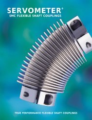
assessories<br />
GD209<br />
RSG 6 WSK 6<br />
Plug-in connector to DIN EN 175301-803<br />
Round connector to DIN 43651<br />
Round connector to DIN 45322<br />
Material No: 314 1046<br />
Material No: 314 1048<br />
small form E<br />
large form A<br />
Material No: 314 1053<br />
Material No: 314 1054<br />
22 AF<br />
small<br />
large<br />
Plug-in connectors are detachable connections and<br />
are used for connecting the locking units of the LLV...<br />
series.<br />
The cable outlet can be rotated through 4 x 90°<br />
(GD209 through 180°) by inserting the contact<br />
carrier accordingly. After plugging the connector into<br />
the device connector it is secured with a machine<br />
screw (supplied). This guarantees an effective seal<br />
between the two and prevents the plug-in connector<br />
from becoming accidentally detached. A screwed<br />
cable gland, thread size Pg 11 (GD209: Pg 9),<br />
serves to seal the cable entry. The contact elements<br />
are fitted with screw terminals and are suitable for<br />
connecting wire cross-sections up to max. 1.5 mm 2 .<br />
When plugged in and secured, the connection meets<br />
the requirements of class of protection IP 66 to IEC<br />
60529. The permissible continuous maximum<br />
temperature is 90°C; the connection can withstand<br />
temperatures of up to 120°C briefly without<br />
suffering any damage. When using the GDSB 211<br />
plug-in connector with integral rectifier, the plug-in<br />
connector can be used as a direct connecting element<br />
between an AC mains system and a DC consumer.<br />
Four silicon diodes form a bridge circuit. A varistor<br />
connected in parallel on the AC side protects the<br />
bridge rectifier against voltage spikes from the<br />
mains.<br />
Round connectors to DIN 43651 are used for<br />
connecting the locking units of the LLV... series. The<br />
connector is a 6-pole version complete with an<br />
earthing connection. After plugging the connector into<br />
the device connector it is secured with a machine<br />
screw (supplied). This guarantees an effective seal<br />
between the two and prevents the connector from<br />
becoming accidentally detached. A screwed cable<br />
gland, thread size Pg 11, serves to seal the cable<br />
entry. The wires are attached by crimping (max. wire<br />
cross-section 1.5 mm 2 ). When plugged in and<br />
secured, the connection meets the requirements of<br />
class of protection IP 65 to IEC 60529. The permissible<br />
continuous maximum temperature is 90°C; the connection<br />
can withstand temperatures of up to 120°C<br />
briefly without suffering any damage.<br />
Round connectors with a screw fixing are used for<br />
connecting the locking units of the LLV040002 series.<br />
This connector is supplied as a 6-pole version. The<br />
mechanical fixing of the round connector to the<br />
corresponding plug, and the earthing connection, is<br />
achieved by means of the metal union nut. A flexible<br />
grommet guarantees no kinks in the outgoing<br />
connecting cable. The wires are connected by<br />
soldering (max. wire cross-section 0.75 mm 2 ). When<br />
plugged in and secured, the connection meets the<br />
requirements of class of protection IP 40 to IEC<br />
60529. The permissible continuous maximum<br />
temperature is 90°C; the connection can withstand<br />
temperatures of up to 120°C briefly without suffering<br />
any damage. The cable outlet can be turned through<br />
180° by installing the contact carrier accordingly.<br />
14<br />
www.kendrionmt.com
assessories<br />
Type 17 00004A00001<br />
Type 17 00504A00100<br />
The strikes are designed for locking solenoid types LLV05500. and LLV080...<br />
Two different strikes are available.<br />
The box strike with a sensor includes a microswitch with an operating contact. The locked state can therefore be indicated at any point in the system<br />
(Umax = 250 VDC or AC; Imax = 0.5 A).<br />
The box strike with a spring enables a door or similar closure to be engaged when the locking bolt is extended.<br />
Operating contact<br />
Switching point<br />
End position<br />
2 No. sealing rings C 60 x 10, DIN 7603 (supplied)<br />
www.kendrionmt.com 15
kendrion magnettechnik worldwide<br />
<strong>Kendrion</strong> Magnettechnik GmbH<br />
August-Fischbach-Strasse 1<br />
78166 Donaueschingen<br />
Germany<br />
Tel. +49 (0) 77 1 80 09-0<br />
Fax +49 (0) 77 1 80 09-63 4<br />
www.kendrionmt.com<br />
info@kendrionmt.com<br />
Engelswies Works<br />
Fred-Hahn-Strasse 33<br />
72514 Inzigkofen-Engelswies, Germany<br />
Tel. +49 (0) 75 75 20 8-0<br />
Fax +49 (0) 75 75 20 8-1 90<br />
www.kendrionmt.com<br />
info@kendrionmt.com<br />
<strong>Kendrion</strong> <strong>Binder</strong> Magnete<br />
Ges.m.b.H.<br />
8552 Eibiswald 269, Austria<br />
Tel. +43 (0) 34 66 42 32 2-0<br />
Fax +43 (0) 34 66 42 72 2<br />
office@kendrion.com<br />
<strong>Kendrion</strong> <strong>Binder</strong> Componentes,<br />
S.L.<br />
Parque Industrial “El Poligono”<br />
c/.Rio Arba, 25<br />
50410 Cuarte de Huerva /<br />
Zaragoza, Spain<br />
Tel. +34 9 76 46 30 40<br />
Fax +34 9 76 46 30 42<br />
guadalupe.cabrera@kendrion.com<br />
Technical offices (Germany)<br />
<strong>Kendrion</strong> Magnettechnik GmbH<br />
Technisches Büro West<br />
Bottroper Strasse 15<br />
46244 Bottrop<br />
Tel. +49 (0) 20 45 41 34 34<br />
Fax +49 (0) 20 45 40 64 26<br />
www.kendrionmt.com<br />
wilhelm.martin@kendrion.com<br />
<strong>Kendrion</strong> Magnettechnik GmbH<br />
Technisches Büro Nord<br />
Delmer Bogen 71<br />
21614 Buxtehude<br />
Tel. +49 (0) 41 61 73 37 77<br />
Fax +49 (0) 41 61 60 07 39 3<br />
www.kendrionmt.com<br />
reinhard.lenser@kendrion.com<br />
Representatives (Germany)<br />
VOR-Steuerungstechnik<br />
Friedrich Rudolph GmbH<br />
Wichernstrasse 9<br />
50389 Wesseling<br />
Tel. +49 (0) 22 36 94 27 88<br />
Fax +49 (0) 22 36 84 27 86<br />
info@vor.de<br />
www.vor.de<br />
Claus Kähne<br />
Industrievertretungen GmbH<br />
Kurmainzer Str. 199a<br />
65936 Frankfurt<br />
Tel. +49 (0) 69 34 05 90 20<br />
Fax +49 (0) 69 34 05 90 27<br />
kaehne.gmbh@t-online.de<br />
RUG<br />
Regler- und Gerätebau GmbH<br />
Karl-Ehmann-Str. 50<br />
73037 Göppingen<br />
Tel. +49 (0) 71 61 85 70<br />
Fax +49 (0) 71 61 85 72 9<br />
jurenka@r-u-g.de<br />
Antriebstechnik Laipple GmbH<br />
Burgstrasse 84<br />
73614 Schorndorf<br />
Tel. +49 (0) 71 81 97 94 92<br />
Fax +49 (0) 71 81 97 94 93<br />
antriebstechnik-laipple@t-online.de<br />
Winfried Kerner GmbH<br />
Ingenieurbüro<br />
Kiebitzweg 11<br />
85375 Neufahrn<br />
Tel. +49 (0) 81 65 52 45<br />
Fax +49 (0) 81 65 62 12 8<br />
www.kerner-gmbh.de<br />
kerner-gmbh@t-online.de<br />
Hans-Christian Pilder<br />
Wirtschaftsingenieur<br />
Ablers 119<br />
88175 Scheidegg<br />
Tel. +49 (0) 17 17 23 13 31<br />
Fax +49 (0) 83 81 94 87 62<br />
www.kendrionmt.com<br />
kendrion@pilder.de<br />
Representatives (worldwide)<br />
Austria<br />
<strong>Kendrion</strong> <strong>Binder</strong> Magnete<br />
Vertriebs. GmbH<br />
Estermannstrasse 27<br />
4020 Linz<br />
Tel. +43 (0) 7 32 77 63 83<br />
Fax +43 (0) 7 32 78 35 58<br />
www.kendrion-binder.at<br />
office@kendrion-binder.at<br />
Belgium, Luxembourg<br />
Bintz technics N.V.<br />
Brixtonlaan 25<br />
1930 Zaventem<br />
Tel. +32 (0) 2 7 20 49 16<br />
Fax +32 (0) 2 7 20 37 50<br />
www.bintz-technics.be<br />
info@bintz.be<br />
Canada<br />
VL Motion Systems Inc.<br />
1105 Goodson Cres.<br />
Oakville, Ontario L6H4A7<br />
Tel. +01 905 842 0244<br />
Fax +01 905 844 1293<br />
vince@vlmotion.com<br />
Denmark<br />
Lind Jacobsen & Co. A / S<br />
Blokken 62<br />
3460 Birkerød<br />
Tel. +45 (0) 45 81 82 22<br />
Fax +45 (0) 45 82 10 22<br />
www.lind-jacobsen.dk<br />
strong@lind-jacobsen.dk<br />
Desim Elektronik APS<br />
Tasingevej 15<br />
9500 Hobro<br />
Tel. +45 (0) 70 22 00 66<br />
Fax +45 (0) 70 22 22 20<br />
www.desim.dk<br />
desim@desim.dk<br />
Farstrup & Benzon A/S<br />
Engholmvej 1, Saunte<br />
3100 Hombaek<br />
Tel. +45 (0) 49 70 40 33<br />
Fax +45 (0) 49 70 40 32<br />
www.safeline.dk<br />
f&b@safeline.dk<br />
Finland<br />
SKS-mekaniikka Oy<br />
Martinkyläntie 50<br />
P.O. Box 122<br />
01721 Vantaa<br />
Tel. +358 (0) 98 52 66 1<br />
Fax +358 (0) 98 52 68 20<br />
www.sks.fi<br />
mekaniikka@sks.fi<br />
Moeller Electric Oy<br />
Sahaajankatu 24<br />
00811 Helsinki<br />
Tel. +358 (0) 9 25 25 21 00<br />
Fax +358 (0) 9 25 25 21 77<br />
www.moeller.fi<br />
info.fin@moeller.net<br />
France<br />
<strong>Binder</strong> Magnetic<br />
1, Allée des Barbanniers<br />
92632 Gennevilliers Cedex<br />
Tel. +33 (0) 1 46 13 80 80<br />
Fax +33 (0) 1 46 13 80 99<br />
info@binder-magnetic.fr<br />
Italy<br />
SPII S.p.A<br />
Via Don Volpi 37<br />
21047 Saronno (VA)<br />
Tel. +39 (0) 2 96 22 921<br />
Fax +39 (0) 2 96 09 611<br />
www.spii.it<br />
info@spii.it<br />
Netherlands<br />
Solar Electro B. V.<br />
Effect 5<br />
6921 RG Duiven<br />
Tel. +31 (0) 26 3 65 29 11<br />
Fax +31 (0) 26 3 65 23 90<br />
www.solarelektro.nl<br />
algemeen@solarelektro.nl<br />
GTI Electroproject B.V.<br />
Grote Tocht 102<br />
1507 CE-Zaandam<br />
Tel. +31 (0) 75 68 11 11 1<br />
Fax +31 (0) 75 63 54 00 3<br />
Norway<br />
Industrielementer AS<br />
Postboks 43<br />
1556 Son<br />
Tel. +47 (0) 64 95 81 32<br />
Fax +47 (0) 64 98 29 29<br />
www.industrielementer.no<br />
post@industrielementer.no<br />
siv. ing. J.F. Knudtzen A/S<br />
Billingstadsletta 97<br />
1396 Billingstad<br />
Tel. +47 (0) 66 98 33 50<br />
Fax +47 (0) 66 98 09 55<br />
www.jfk.no<br />
firmapost@jfk.no<br />
South Africa<br />
Magnete Service <strong>Binder</strong><br />
P.O. Box 44051<br />
2104 Linden<br />
Tel. +27 (0) 11 46 2-32 08<br />
Fax +27 (0) 11 46 2-33 04<br />
info@binder.co.za<br />
Spain, Portugal<br />
<strong>Binder</strong> Magnete Iberica S.L.<br />
Apartado de Correos 116<br />
Costa Zefir 99<br />
43892 Miami-Playa (Tarragona)<br />
Tel. +34 9 77 17 27 07<br />
+34 9 77 81 04 29<br />
Fax +34 9 77 17 01 82<br />
www.binder-es.com<br />
binder@binder-es.com<br />
Sweden<br />
Industrikomponenter AB<br />
Industrivägen 12<br />
17148 Solna<br />
Tel. +46 (0) 8 51 48 44 00<br />
Fax +46 (0) 8 51 48 44 01<br />
www.inkom.se<br />
info@inkom.se<br />
Uno Gunnarsson / Höör AB<br />
Box 64<br />
24322 Höör<br />
Tel. +46 (0) 4 13 24 54 0<br />
Fax +46 (0) 4 13 23 18 3<br />
Moeller Electric AB<br />
Granitvägen 2<br />
55303 Jönköping<br />
Tel. +46 (0) 86 32 30 00<br />
Fax +46 (0) 86 32 32 99<br />
Switzerland<br />
<strong>Kendrion</strong> <strong>Binder</strong> Magnet AG<br />
Albisstrasse 26<br />
8915 Hausen a/A<br />
Tel. +41 (0) 17 64 80 60<br />
Fax +41 (0) 17 64 80 69<br />
www.kendrion.ch<br />
binder.magnet@kendrion.com<br />
United Kingdom<br />
<strong>Kendrion</strong> <strong>Binder</strong> Magnete<br />
(U.K.) Ltd.<br />
Huddersfield Road, Low Moor<br />
Bradford, West Yorkshire,<br />
BD12 0TQ<br />
Tel. +44 (0) 12 74 60 11 11<br />
Fax +44 (0) 12 74 69 10 93<br />
www.kendrion-binder.co.uk<br />
sales@kendrion-binder.co.uk<br />
USA<br />
Gradframe Inc.<br />
950 E. Baldwin Road<br />
Palatine IL 60074<br />
Tel. +01 847 991 1788<br />
Fax +01 847 991 1788<br />
gradframe@aol.com<br />
This publication is for information<br />
purposes only and should not be<br />
regarded as a binding presentation of<br />
the products, unless we expressly<br />
confirm otherwise.<br />
We reserve the right to make changes<br />
to the specification, form, price and<br />
availability of the products described<br />
herein at any time without prior notice.<br />
Each product may be used only for its<br />
intended purpose.<br />
We reserve to make changes to the<br />
product design.<br />
www.kendrionmt.com