SERVICE MANUAL - HWH Corporation
SERVICE MANUAL - HWH Corporation
SERVICE MANUAL - HWH Corporation

You also want an ePaper? Increase the reach of your titles
YUMPU automatically turns print PDFs into web optimized ePapers that Google loves.
HW<br />
CORPORATION<br />
H<br />
R<br />
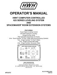
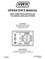
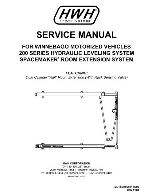
<strong>SERVICE</strong> <strong>MANUAL</strong><br />
FOR WINNEBAGO MOTORIZED VEHICLES<br />
200 SERIES HYDRAULIC LEVELING SYSTEM<br />
SPACEMAKER ROOM EXTENSION SYSTEM<br />
R<br />
FEATURING:<br />
Dual Cylinder "Rail" Room Extension (With Rack Sensing Valve)<br />
<strong>HWH</strong> CORPORATION<br />
(On I-80, Exit 267 South)<br />
2096 Moscow Road | Moscow, Iowa 52760<br />
Ph: 800/321-3494 (or) 563/724-3396 | Fax: 563/724-3408<br />
www.hwh.com<br />
ML11570/MI91.0006<br />
05MAY04
SECTION 1<br />
SECTION<br />
1<br />
TROUBLE<br />
SHOOTING<br />
GUIDE<br />
SECTION<br />
2<br />
FIGURES<br />
2 PART FOLDER<br />
HOW TO USE <strong>MANUAL</strong><br />
NOTE: This manual will work for systems with single cylinder room extensions also. The only difference is the exclusion<br />
of rack sensing valve problems or adjustments.<br />
This manual is written in two sections. Section 1 is the Trouble Shooting Guide. Section 2 is the figures. Begin diagnosis of<br />
the system with Section 1, the Trouble Shooting Guide. The Trouble Shooting Guide is broken into 3 columns, Problem,<br />
Solutions and Figures. Under Problems, find the symptom you have encountered. The testing and repair for that problem is<br />
in the Solution (center) column. Diagrams for a particular Problem and Solution are in the Figures (right hand) column. This<br />
column will direct you to the proper figure in Section 2, Figures, for a more detailed view.<br />
Before beginning your repair, it is IMPORTANT to read the CAUTIONS and NOTES AND CHECKS in the first section, TROUBLE<br />
SHOOTING GUIDE. In many cases this will save time and mistakes when trouble shooting a system.<br />
This Repair Manual is offered as a guide only. It is impossible to anticipate every problem or combination of problems. For<br />
any problems encountered that are not addressed in this manual, contact <strong>HWH</strong> <strong>Corporation</strong> for assistance. (800-321-3494)<br />
The room should be fully retracted before Trouble Shooting the system. If the room will not retract, use the manual retract procedure<br />
on pages MP35.9410 and MP35.9490.<br />
Make sure all room locks and the manual retract winch are not engaged before trouble shooting the system.<br />
PROCEED WITH TROUBLE SHOOTING GUIDE<br />
MI91.1005<br />
05AUG96
TROUBLE SHOOTING<br />
WARNING!<br />
BLOCK FRAME AND TIRES SECURELY BEFORE CRAWLING UNDER VEHICLE. DO NOT USE THE LEVELING<br />
JACKS OR AIR SUSPENSION TO SUPPORT VEHICLE WHILE UNDER VEHICLE OR CHANGING TIRES. VEHICLE<br />
MAY DROP AND OR MOVE FORWARD OR BACKWARD WITHOUT WARNING CAUSING INJURY OR DEATH.<br />
WHEN ROUTING OR REROUTING HYDRAULIC HOSES AND WIRES, BE SURE THEY ARE NOT EXPOSED TO ENGINE<br />
EXHAUST OR ANY HIGH TEMPERATURE COMPONENTS OF THE VEHICLE.<br />
NEVER PLACE HAND OR OTHER PARTS OF THE BODY NEAR HYDRAULIC LEAKS. OIL MAY CUT AND<br />
PENETRATE THE SKIN CAUSING INJURY OR DEATH.<br />
SAFETY GLASSES ARE TO BE WORN TO PROTECT EYES FROM DIRT, METAL CHIPS, OIL LEAKS, ETC. FOLLOW<br />
ALL OTHER SHOP SAFETY PRACTICES.<br />
NOTES AND CHECKS<br />
Read and check before proceeding with Trouble Shooting Steps.<br />
NOTE: <strong>HWH</strong> CORPORATION ASSUMES NO LIABILITY<br />
FOR DAMAGES OR INJURIES RESULTING FROM THE<br />
INSTALLATION OR REPAIR OF THIS PRODUCT.<br />
1. If the room extension cannot be retracted, see Figures pages<br />
MP35.9410 and MP35.9490 for temporary measures. Make<br />
sure the manual retract valves are closed before trouble shooting.<br />
IMPORTANT : The room extension will not operate unless a<br />
jack is extended enough to turn a Jacks Down Warning light on,<br />
but the vehicle should NOT be supported by the leveling jacks<br />
when working on the room extension.<br />
2. Check that the oil reservoir is full with the room in the fully<br />
retracted position.<br />
3. Batteries should read 12.6 volts. Batteries must be in good<br />
condition with no weak cells. An alternator, converter or battery<br />
charger will not supply enough power for the system to operate<br />
properly.<br />
4. Proper ground of all components is critical. See the electrical<br />
circuit for specific grounds required. Faulty grounds,<br />
especially for the solenoid manifold or the pump assembly,<br />
may cause component damage and /or improper or erratic<br />
operation.<br />
This manual is intended for use by experienced mechanics<br />
with knowledge of hydraulic and automotive electrical<br />
systems. People with little or no experience with <strong>HWH</strong><br />
Room Extension systems should contact <strong>HWH</strong> technical<br />
service (800-321-3494) before beginning. Special attention<br />
should be given to all cautions, wiring, and hydraulic dia-<br />
grams.<br />
Suggested tools for trouble shooting the <strong>HWH</strong> room extension<br />
systems:<br />
JUMPER WIRES (UP TO 10 GAUGE)<br />
PRESSURE GAUGE (3500 PSI MIN.)<br />
MULTI-METER<br />
12 VOLT TEST LIGHT<br />
PROCEED WITH THE TROUBLE<br />
SHOOTING STEPS ON THE<br />
FOLLOWING PAGE<br />
MI91.1013<br />
25APR11
TROUBLE SHOOTING<br />
The following is a list of possible problems and solutions which might occur to the room extensions. Only qualified technicians<br />
should install or repair room extension systems. An understanding of the operation of the room extension hydraulic and electrical<br />
components is required. Contact <strong>HWH</strong> <strong>Corporation</strong> technical service for assistance at (800) - 321 - 3494.<br />
The following conditions must be met for the room extension to operate. The ignition must be in the "ACC" position. The park<br />
brake must be set. The <strong>HWH</strong> leveling system panel must be on. A red "Jack Down Warning Light" on the <strong>HWH</strong> panel must be<br />
on. (A jack must be extended approximately two inches)<br />
PROBLEM<br />
SOLUTION<br />
FIGURES<br />
Part 1<br />
The <strong>HWH</strong> leveling<br />
system light<br />
panel will not turn<br />
on.<br />
Check for power on the red wire connected to the fuse holder on the<br />
back of the light panel. If power is present, check the fuse and the<br />
park brake circuit. Then replace the panel if necessary.<br />
RED ACCESSORY<br />
POWER<br />
REFER TO MP85.9417<br />
POWER<br />
HARNESS<br />
FROM OEM<br />
WK<br />
Power is not present on the red wire at the back of the light panel.<br />
Check for +12 power on the red wire (<strong>HWH</strong>) and the wire marked "WK"<br />
(WINNEBAGO) at the 3 pin UML. If power is present there is a problem<br />
with the red wire in the <strong>HWH</strong> harness.<br />
3 PIN UML FROM<br />
<strong>HWH</strong> POWER<br />
HARNESS<br />
RED<br />
+12<br />
ACC.<br />
REFER TO MP85.9413<br />
POWER <strong>HWH</strong><br />
HARNESS POWER<br />
FROM OEM HARNESS<br />
REFER TO MP85.9423<br />
This section is concerned with the WINNEBAGO circuitry.<br />
Power is not present at the 3 pin UML. Check for power on Terminal<br />
(30) of the Accessory relay. If power is not present there is a problem<br />
with the WINNEBAGO wire marked "1WK", the 15 amp fuse or the<br />
wire marked "CA".<br />
CA 1WK<br />
CHASSIS<br />
15 AMP<br />
BATTERY FUSE<br />
ACCESSORY<br />
RELAY<br />
REFER TO MP85.9413<br />
30<br />
If power is present on Terminal (30), Check Terminal (85). If power<br />
is present, there is a problem with the WINNEBAGO wire marked "LD"<br />
or the accessory power supply.<br />
ACCESSORY<br />
ACCESSORY<br />
RELAY<br />
LD 85<br />
REFER TO MP85.9413<br />
If power is present on Terminal (85), check the ground on Terminal<br />
(86). Then check for power on terminal (87). If there is no power on<br />
Terminal (87) replace the relay. If there is power, the problem is with<br />
the WINNEBAGO wire marked "WK".<br />
WK<br />
ACCESSORY<br />
RELAY<br />
87<br />
86<br />
MG<br />
REFER TO MP85.9413<br />
MI91.2022<br />
16APR96
PROBLEM<br />
SOLUTION<br />
FIGURES<br />
Part 2<br />
The pump will not<br />
run when the room<br />
extension switch<br />
is pushed toward<br />
Extend or Retract<br />
NOTE : The ignition<br />
must be in<br />
the "ACC" position.<br />
The leveling<br />
system panel<br />
must be on and a<br />
red "Jack Down<br />
warning light"<br />
must be on.<br />
Run the leveling system. If the pump runs go to part B of the solution.<br />
If the pump does not run start at part A.<br />
A.<br />
Check for a +12 power on Terminals (1) and (3) of the pump relay.<br />
If there is no power on Terminal (3) : Check the connection, battery<br />
cable and battery.<br />
If there is no power on Terminal (1) : Check for power at the back<br />
of the leveling panel on the pump pin. If power is not present replace<br />
the panel. If power is present repair the blue wire.<br />
PUMP<br />
RELAY<br />
1<br />
3<br />
REFER TO MP85.9417<br />
CONTROL<br />
PANEL<br />
WHITE<br />
GROUND<br />
11 PIN<br />
MTA<br />
HARNESS<br />
REFER TO MP85.9417<br />
PUMP<br />
RELAY<br />
If power is present on Terminals (1) and (3) : Ground Terminal (2).<br />
If the pump does not run check for +12 power on terminal (4) white<br />
grounding Terminal (20). If power is present check that the pump is<br />
properly grounded. If it is replace the pump. If power is not present<br />
on Terminal (4), replace the pump relay.<br />
ORANGE<br />
2<br />
REFER TO MP85.9417<br />
B. If the pump works properly for the leveling system. Check that<br />
the orange wire at the pump relay is connected properly.<br />
Using a test light hooked to +12, check for ground on the white wire<br />
of the 6 pin UML connector supplied by <strong>HWH</strong>. If no ground is present,<br />
there is a problem with the harness. If there is a ground, check the<br />
number (2) pin on the room control switch. If there is no ground there<br />
is a problem with the WINNEBAGO wire marked "DX". If ground is<br />
present, check pins (1) and (3) for ground while pushing the room<br />
control switch. If ground is not present, replace the switch. If ground<br />
is present, check for ground at the 6 pin UML on the WINNEBAGO<br />
wire marked "DW" while pushing the button. If ground is present there<br />
is a problem with the orange wire in the <strong>HWH</strong> harness. If there is no<br />
ground the problem is with the WINNEBAGO wire marked "DW".<br />
4<br />
5<br />
6<br />
1<br />
2<br />
3<br />
ROOM<br />
CONTROL<br />
SWITCH<br />
ORANGE<br />
WHITE<br />
BLACK<br />
6 PIN UML<br />
ORANGE<br />
(DU)<br />
PUMP<br />
1DW<br />
DX<br />
2DW<br />
DW<br />
6 PIN<br />
UML<br />
REFER TO MP85.9413<br />
<strong>HWH</strong> ROOM<br />
HARNESS EXTENSION<br />
FROM OEM HARNESS<br />
6 PIN UML<br />
REFER TO MP85.9423<br />
WHITE (DX)<br />
GROUND<br />
RED (EA)<br />
ACC.<br />
+12 VOLT<br />
REFER TO MP85.9423<br />
MI91.2027<br />
16APR96
A<br />
B<br />
PROBLEM<br />
SOLUTION<br />
FIGURES<br />
Part 3<br />
The pump runs<br />
but the room will<br />
not extend.<br />
RETRACT<br />
SOLENOID<br />
VALVE<br />
1R<br />
"T"<br />
HANDLE<br />
a. The pump runs<br />
under no load.<br />
The retract valve is open. Make sure the solenoid valve "T" handle is<br />
closed. Check for +12 power on the black wire. If power is not present<br />
replace the retract valve.<br />
BLACK<br />
MANIFOLD/PUMP<br />
RELAY HARNESS<br />
REFER TO MP85.9437<br />
DU<br />
4<br />
5<br />
1<br />
2<br />
If there is power on the black wire, check the number (4) terminal on<br />
the room control switch, while pushing the switch toward the "EXTEND"<br />
position. If there is power, replace the switch. If there is no power on<br />
the number (4) terminal, the WINNEBAGO wire marked "DU" or the<br />
black wire in the <strong>HWH</strong> harness is shorted to a +12 supply.<br />
6<br />
ROOM<br />
CONTROL<br />
SWITCH 6 PIN<br />
UML<br />
BLACK<br />
<strong>HWH</strong> ROOM<br />
EXTENSION<br />
CONTROL<br />
HARNESS<br />
REFER TO MP85.9413<br />
3<br />
b. The pump runs<br />
under a load.<br />
The extend solenoid valve is not opening. While pushing the room<br />
control switch toward "EXTEND", check between the yellow and white<br />
wire of the extend valve plug for +12 power. If power is present, replace<br />
the extend solenoid valve. If power is not present, check between<br />
the yellow wire and ground. If power is present, repair the white<br />
wire in the plug.<br />
WHITE<br />
WIRES TO<br />
GROUND<br />
STUD<br />
1E<br />
A<br />
B<br />
EXTEND<br />
SOL.<br />
VALVE<br />
YELLOW<br />
REFER TO MP85.9437<br />
Power is not present on the yellow and white wire of the extend<br />
valve plug.<br />
DR<br />
4<br />
5<br />
1<br />
2<br />
While pushing the room control switch toward "EXTEND", check for<br />
power on Terminal 6 of the room control switch. If power is present,<br />
there is a problem with the WINNEBAGO wire marked "DR" or the<br />
yellow wire in the <strong>HWH</strong> harness. If there is no power, check Terminal<br />
5 of the room control switch. The switch does not have to be pushed.<br />
If there is power on Terminal 5, the switch needs to be replaced.<br />
6<br />
3<br />
ROOM<br />
CONTROL<br />
SWITCH 6 PIN<br />
UML<br />
<strong>HWH</strong> ROOM YELLOW<br />
EXTENSION<br />
CONTROL<br />
HARNESS<br />
REFER TO MP85.9413<br />
MI91.2032<br />
16APR96
A<br />
PROBLEM<br />
3b. continued<br />
SOLUTION<br />
There is no power to the room control switch. Check Terminals (30)<br />
and (85) of the slide out relay. If power is not present, there is a problem<br />
with the WINNEBAGO wire marked "EA" or the red wire in the<br />
<strong>HWH</strong> harness. If there is power on Terminals (30) and (85) check that<br />
Terminal (86) has a ground. If there is no ground, check that a red "Jack<br />
Down Warning Light" is on. If a light is on, there is a problem with<br />
the WINNEBAGO wire marked "DY" or the brown wire of the <strong>HWH</strong><br />
harness.<br />
2EA<br />
FIGURES<br />
EA<br />
1EA 87 86<br />
DY<br />
87A<br />
85<br />
30<br />
SLIDE OUT<br />
RELAY<br />
REFER TO MP85.9413<br />
If Terminal (86) has a ground check Terminal (87) for +12 power. If there<br />
is no power, replace the slide out relay. If there is power on Terminal<br />
(87), the problem is with the WINNEBAGO wire marked "EB".<br />
6 PIN<br />
<strong>HWH</strong> ROOM UML<br />
EXTENSION<br />
CONTROL<br />
HARNESS<br />
DY<br />
EA<br />
RED<br />
BROWN<br />
REFER TO MP85.9413<br />
Part 4<br />
The room will extend<br />
but not retract.<br />
1E<br />
EXTEND<br />
SOL.<br />
VALVE<br />
4a. The pump runs<br />
under no load.<br />
The extend valve is open. Make sure the solenoid "T" handle is closed.<br />
Check for +12 power on the yellow wire. If power is not present, replace<br />
the extend valve.<br />
B<br />
YELLOW<br />
REFER TO MP85.9437<br />
DR<br />
4<br />
1<br />
If there is power on the yellow wire, check the (6) terminal on the<br />
room control switch while pushing the switch towards "RETRACT".<br />
If there is power replace the switch. If there is no power on the (6) terminal,<br />
the WINNEBAGO wire marked "DR" or the yellow wire in the<br />
<strong>HWH</strong> harness is shorted to a +12 supply.<br />
5<br />
6<br />
2<br />
3<br />
ROOM<br />
CONTROL<br />
SWITCH 6 PIN<br />
UML<br />
<strong>HWH</strong> ROOM YELLOW<br />
EXTENSION<br />
CONTROL<br />
HARNESS<br />
REFER TO MP85.9413<br />
MI91.2042<br />
16APR96
A<br />
B<br />
PROBLEM<br />
SOLUTION<br />
FIGURES<br />
4b. The pump<br />
runs under a load.<br />
The retract solenoid valve is not opening. While pushing the room<br />
control switch toward "RETRACT", check between the black and white<br />
wires of the retract valve plug for +12 power. If power is present replace<br />
the retract solenoid valve. If power is not present check between<br />
the black wire and ground. If power is present, repair the white wire<br />
in the plug.<br />
Power is present on the black and white wire of the retract valve<br />
plug. Check for power on Terminal (4) of the room control switch, while<br />
pushing toward "RETRACT". If power is present, there is a problem<br />
with the WINNEBAGO wire marked "DU" or the black wire of the <strong>HWH</strong><br />
harness. If there is no power on Terminal (4), replace the switch.<br />
Pushing toward "RETRACT". If power is present, there is a problem<br />
with the WINNEBAGO wire marked "DU" or the black wire of the <strong>HWH</strong><br />
harness. If there is no power on Terminal (4), replace the switch.<br />
RETRACT<br />
SOLENOID<br />
VALVE<br />
"T"<br />
HANDLE<br />
WHITE<br />
WIRES TO<br />
BLACK<br />
GROUND<br />
STUD<br />
MANIFOLD/PUMP<br />
RELAY HARNESS<br />
REFER TO MP85.9437<br />
1R<br />
ROOM<br />
CONTROL<br />
SWITCH<br />
BLACK<br />
<strong>HWH</strong> ROOM EXTENSION<br />
CONTROL HARNESS<br />
4<br />
5<br />
6<br />
DU<br />
REFER TO MP85.9413<br />
1<br />
2<br />
3<br />
6 PIN<br />
UML<br />
Part 5<br />
The room moves<br />
erratically from<br />
side to side (walking)<br />
as it extends<br />
or retracts (dual<br />
cylinder room extensions<br />
only).<br />
Check that the pivot bracket is free to pivot. Vertical clearance must be<br />
between 0.030 and 0.120 inches. Check that the inner tubes are free of<br />
paint or undercoating. Check that the left cylinder hydraulic lines are not<br />
wire tied to the room closer than 12 inches to the rack sensing valve<br />
valve support arm. (SEE MP45.9415)<br />
Check that the strike plate is mounted solidly to the room, and that the<br />
rack sensing valve plunger is properly positioned on the strike plate.<br />
Check that the plunger is not bent. (SEE MP35.9410) Check that the<br />
room itself is not binding on seals or other interferences. Then replace<br />
the rack sensing valve. (SEE MP45.9420)<br />
REFER TO MP45.9415<br />
PIVOT BOLT<br />
REFER TO MP35.9410<br />
REFER TO MP45.9420<br />
Part 6<br />
The ends of the<br />
room do not move<br />
at an equal distance<br />
from the vehicle.<br />
The rack sensing valve needs to be adjusted. See MP45.9420 for valve<br />
adjustment procedures.<br />
REFER TO MP45.9420<br />
MI91.2047<br />
11APR05
PROBLEM<br />
SOLUTION<br />
FIGURES<br />
Part 7<br />
The room creeps<br />
out after being retracted.<br />
The following deals with either single or dual cylinder room extensions.<br />
There are three possibilities:<br />
A. An extend solenoid valve is leaking.<br />
B. A room extension cylinder has an internal leak.<br />
C. The manifold check valve is leaking.<br />
NOTE : If the room creeps out 1" or less, the problem is most likely<br />
the check valve.<br />
Retract the room completely. Remove the hydraulic line for the cap<br />
end of the cylinder at the manifold. Hold the line with the hose end<br />
in an upright position. Press the rocker switch for that room to the<br />
RETRACT position.<br />
CAP<br />
END<br />
ROD<br />
END<br />
HYDRAULIC<br />
CYLINDERS<br />
CAP ROD<br />
END END<br />
ROOM EXTENSION<br />
REFER TO MP65.9425<br />
If fluid flows from the manifold fitting, the extend solenoid valve needs<br />
to be changed.<br />
1R<br />
1E<br />
EXTEND<br />
SOLENOID<br />
VALVE<br />
REFER TO MP85.9437<br />
If no fluid flows from either the hose end or the manifold fittings, inspect<br />
the manifold check valve. There is a spring below the cap.<br />
DO NOT lose the spring. Check for cuts on the poppet o-ring. Check<br />
the poppet and cap for burrs. The poppet should easily slide in the<br />
cap.<br />
MANIFOLD<br />
CHECK VALVE<br />
MANIFOLD<br />
CHECK VALVE<br />
CAP<br />
"O" RING<br />
SPRING<br />
POPPET<br />
REFER TO MP85.9437<br />
If the check valve is OK, or if fluid flows from the hose end, the room<br />
extension cylinder should be replaced. See MP45.9415<br />
REFER TO MP45.9415<br />
Part 8<br />
The room creeps<br />
back in after being<br />
extended.<br />
Replace the retract solenoid valve for that room extension. This is<br />
the only possibility that would cause this problem.<br />
RETRACT<br />
SOLENOID<br />
VALVE<br />
1R<br />
1E<br />
REFER TO MP85.9437<br />
MI91.2052<br />
17APR96
PROBLEM<br />
SOLUTION<br />
FIGURES<br />
Part 9<br />
The room does<br />
not seal tightly<br />
when fully retracted<br />
or extended.<br />
The room stops need to be adjusted. See the adjustment section of<br />
MP45.9415<br />
REFER TO MP45.9415<br />
MI91.2056<br />
17APR96
<strong>MANUAL</strong> ROOM RETRACT PROCEDURE<br />
USE ONLY WHEN ROOM CANNOT BE RETRACTED WITH THE ROOM CONTROL<br />
SWITCH OR THE <strong>MANUAL</strong> RETRACT WINCH.<br />
THIS SHOULD BE DONE BY A CERTIFIED TECHNICIAN ONLY.<br />
CONTACT <strong>HWH</strong> CORPORATION FOR ASSISTANCE AT (1-800-321-3494).<br />
When extending or retracting the room, if one side of the room does not move, release the room control switch immediately.<br />
The rack sensing valve plunger (1, FIGURE 1) may be stuck, bent or not touching the strike plate (2, FIGURE 1).<br />
REAR ROOM<br />
EXTENSION TUBES<br />
4<br />
3<br />
1<br />
FRONT ROOM<br />
EXTENSION TUBES<br />
5<br />
2<br />
WARNING:<br />
FIGURE 1<br />
ROOM IN EXTENDED POSITION<br />
Refer to page MP35.9490 in the Operator’s Manual or the repair manual, and try to manually retract the room, if it is extended.<br />
If the manual winch provided will not retract the room, DO NOT USE ALTERNATE DEVICES SUCH AS A POWER<br />
WINCH. If possible repair the rack sensing valve (3, FIGURE 1) before retracting the room. If repair is not possible, release the<br />
pressure on the manual retract winch. Remove the check valve cap (4, FIGURE 1) from the back of the rack sensing valve. Remove<br />
the check valve poppet (5, FIGURE 1). Replace the check valve cap. Retract the room using the manual retract<br />
winch according to MP35.9490. DO NOT use the room extension until the rack sensing valve has been replaced. Leave<br />
the manual winch in place and have the room extension repaired.<br />
ROOM EXTENSION SOLENOID VALVE "T" HANDLES MUST BE IN THE OPEN POSITION WHEN THE<br />
<strong>MANUAL</strong> RETRACT WINCH IS CONNECTED. DO NOT USE THE ROOM EXTENSION OR LEVELING SYSTEM WHEN THE<br />
ROOM EXTENSION HYDRAULIC HOSES ARE DISCONNECTED.<br />
2<br />
1<br />
3<br />
4<br />
FIGURE 2<br />
ROOM IN RETRACTED POSITION<br />
If one side of the room will not move while extending, repair the rack sensing valve before continuing. Remove the cylinder adjusting<br />
locknut (1, FIGURE 2). Turn the cylinder adjusting rod (2, FIGURE 2) clockwise as far as possible. If this is not enough<br />
room to work on the valve, remove the cylinder mounting plate nuts (3, FIGURE 2) and the cylinder mounting plate (4, FIGURE<br />
2). The room can then be pulled out far enough to work on the rack sensing valve. Contact <strong>HWH</strong> <strong>Corporation</strong>, 1-800-321-3494,<br />
for the correct rack sensing valve and cylinder replacement and adjustment instruction sheets.<br />
MP35.9410<br />
02FEB12
<strong>MANUAL</strong> ROOM RETRACT PROCEDURE<br />
(WITH SOLENOID VALVES WITH VALVE RELEASE "T" HANDLES)<br />
(USE ONLY WHEN THE ROOM WILL NOT RETRACT WITH THE ROOM CONTROL SWITCH)<br />
OVERVIEW<br />
The room can be retracted manually if a hydraulic or electric<br />
failure prevents the room from being retracted using the<br />
CONTROL SWITCH. For normal retract sequence see the<br />
ROOM SLIDE RETRACT PROCEDURES. Refer to the<br />
vehicle manufacturer for storage location of the<br />
retract device and information for connecting the<br />
device to the room.<br />
IMPORTANT: If the vehicle is not equipped with a winch,<br />
DO NOT use other pulling devices to retract the room.<br />
Follow steps 2 and 3 and try pushing the room in.<br />
Contact the vehicle manufacturer or <strong>HWH</strong> Customer<br />
Service at 1-800-321-3494 or 563-724-3396 for assistance.<br />
WARNING: THE <strong>MANUAL</strong> RETRACT WINCH IS<br />
EQUIPPED FOR <strong>MANUAL</strong>LY RETRACTING THE ROOM<br />
ONLY. IT IS NOT TO BE USED FOR LIFTING OR ANY<br />
OTHER APPLICATION. HIGH FORCES ARE CREATED<br />
WHEN USING A WINCH, CREATING POTENTIAL SAFETY<br />
HAZARDS. FAILURE TO FOLLOW ALL CAUTIONS AND<br />
INSTRUCTIONS MAY CAUSE FAILURE OF THE <strong>MANUAL</strong><br />
RETRACT WINCH OR CONNECTIONS RESULTING IN<br />
DAMAGE OR PERSONAL INJURY. MAINTAIN FIRM GRIP<br />
ON THE WINCH HANDLE AT ALL TIMES. NEVER RELEASE<br />
THE HANDLE WHEN RATCHET LEVER IS IN THE OFF<br />
POSITION AND THE WINCH IS LOADED. THE WINCH<br />
HANDLE COULD SPIN VIOLENTLY AND CAUSE PERSONAL<br />
INJURY. CHECK THE WINCH AND STRAPS FOR DAMAGE<br />
OR WEAR, AND CHECK FOR PROPER RATCHET OPERATION<br />
ON EACH USE OF THE WINCH. DO NOT USE IF DAMAGED<br />
OR WORN.<br />
1. Retract jacks following the LEVELING SYSTEM RETRACT<br />
PROCEDURE.<br />
NOTE : When manually retracting the room, make sure the<br />
jacks are retracted before retracting the room.<br />
2. Locate the HYDRAULIC PUMP/MANIFOLD unit.<br />
"T"<br />
HANDLES<br />
SOLENOID VALVES<br />
NOTE : The "T" HANDLE may turn easily at first but<br />
will become more difficult to turn as an internal spring is<br />
compressed. Be sure to open both valves completely<br />
(about six turns of the "T" HANDLE).<br />
NOTE : The room may move slightly as the SOLENOID VALVES<br />
are opened and internal pressure is released.<br />
4. Locate the <strong>MANUAL</strong> RETRACT WINCH and connect it to<br />
the room according to the vehicle manufacturer’s instructions.<br />
To extend the WINCH STRAP firmly grasp WINCH HANDLE,<br />
place RATCHET LEVER in its OFF position, and slowly rotate<br />
the WINCH HANDLE counterclockwise, keeping a firm grip on<br />
the handle. When enough WINCH STRAP is extended, place the<br />
RATCHET LEVER in its ON position and slowly rotate the WINCH<br />
HANDLE clockwise until the RATCHET LEVER locks.<br />
ON<br />
OFF<br />
WINCH STRAP<br />
RATCHET LEVER<br />
WINCH HANDLE<br />
<strong>MANUAL</strong> RETRACT WINCH<br />
WINCH<br />
HOOK<br />
5. Slowly winch the room in by turning the WINCH HANDLE<br />
clockwise. The RATCHET LEVER should produce a loud, sharp,<br />
clicking noise.<br />
NOTE : Winching the room in quickly will raise pressure in the<br />
hydraulic fluid and make winching more difficult.<br />
WARNING:<br />
OPERATE THE <strong>MANUAL</strong> RETRACT WINCH<br />
BY HAND POWER ONLY. IF THE WINCH CANNOT BE<br />
CRANKED EASILY WITH ONE HAND IT IS PROBABLY OVER-<br />
LOADED. IF WINCHING BECOMES TOO DIFFICULT STOP<br />
AND CHECK FOR OBSTRUCTIONS OR RESTRICTIONS ON<br />
THE ROOM AND ROOM EXTENSION MECHANISM.<br />
6. When the room is fully retracted, engage the room locking<br />
devices. Leave the retract winch in place.<br />
WARNING: THE ROOM EXTENSION SOLENOID VALVE<br />
"T" HANDLES MUST BE IN THE OPEN POSITION WHEN THE<br />
<strong>MANUAL</strong> RETRACT WINCH IS ENGAGED.<br />
HYDRAULIC PUMP/MANIFOLD<br />
7. The system should be repaired before using again.<br />
3. Open the SOLENOID VALVES by turning the "T" HANDLES<br />
counterclockwise.<br />
MP35.9490<br />
02FEB12
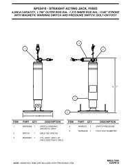
CYLINDER REPLACEMENT<br />
ROOM EXTENSION ASSEMBLY<br />
DUAL CYLINDER ROOM EXTENSION<br />
RIGHT ROOM<br />
EXTENSION<br />
TUBES<br />
8<br />
INNER<br />
TUBE<br />
6<br />
7<br />
LEFT ROOM<br />
EXTENSION<br />
TUBES<br />
RACK<br />
SENSING<br />
VALVE<br />
SUPPORT<br />
ARM<br />
LEFT CYLINDER<br />
HYDRAULIC LINES<br />
12.00"<br />
FIRST<br />
WIRE TIE<br />
TO ROOM<br />
5<br />
2<br />
3<br />
10 9 1<br />
INNER TUBE<br />
PIVOT<br />
BRACKET<br />
4<br />
PIVOT BOLT<br />
CYLINDER REPLACEMENT<br />
Extend the room until the cylinder mounting bolts (1) are<br />
visible. Make sure there is adequate room to work with the<br />
hose connections at the rack sensing valve. Open the<br />
extend and retract room extension solenoid valve "T"<br />
handles. Remove the cylinder adjusting lock nut (2). Measure<br />
the distance between the end of the cylinder adjusting rod<br />
(3) and the cylinder mounting plate (4). Add 1/4 inch to that<br />
measurement, this will allow for easy adjustment of the room<br />
after installing the new cylinder. Remove the two hose guide<br />
mounting bolts (6). (this is not necessary when removing the<br />
right cylinder). Remove the cylinder hoses from the sensing<br />
valve (7) and the tee fitting (8). Plug the hose ends and tie a<br />
wire to the two hoses, this will help when feeding the hoses<br />
back through the room extension tubes. Remove the<br />
cylinder mounting plate mounting nuts (5). Remove the<br />
cylinder assembly. Before installing the new cylinder,<br />
clean all excess oil from the extension tubes. Swab the<br />
tube thoroughly with mild solvent and rags. Excess oil<br />
left in the tubes may leak giving the appearance of a<br />
leaky room cylinder or hose connection.<br />
CYLINDER ADJUSTMENT<br />
Pull the rod out of the new cylinder approximately 1 1/2 feet.<br />
Some fluid will come out of the fittings. Move the hoses from<br />
the old cylinder to the new cylinder. DO NOT over tighten<br />
the fittings. Move the cylinder mounting plate to the new rod.<br />
Use the measurement from the old rod. Feed the hoses and<br />
new cylinder into the extension tube. Line up the cylinder<br />
mounting holes and replace the cylinder bolts (1). Reattach<br />
the hoses and hose guide. Push the rod in and attach the<br />
cylinder mounting plate. Close the room extension solenoid<br />
valves. Purge the air from the system by using the following<br />
steps. Retract the room completely. Extend the room 1 foot<br />
then retract the room completely. Extend the room 2 feet<br />
then retract the room completely. Extend the room fully then<br />
retract the room completely. Extend the room fully and hold<br />
the button toward extend for 5 seconds. Check for leaks.<br />
After replacement is complete check oil level in the tank.<br />
Tightening of hose ends: If tightening a new hose end,<br />
make the hose end snug (finger tight) on the fitting, then<br />
tighten the hose end 1/3 turn (2 FLATS). If tightening an<br />
existing hose end, tighten the hose end to snug plus 1/4<br />
turn (1 FLAT).<br />
Extend the room completely. Turn the cylinder adjustment<br />
rod (3) in or out until the room seals are properly<br />
compressed. Replace and tighten the cylinder adjusting<br />
lock nut (2). The in stop is adjusted by loosening the lock nut<br />
(9) and turning the adjusting nut (10) in or out until the seals<br />
are properly compressed. This adjustment should not have<br />
to be changed after replacing the cylinder.<br />
IMPORTANT: Watch carefully that the room does not<br />
rack excessively or extend too far when operating the<br />
first time after replacing the cylinders.<br />
MP45.9415<br />
31JAN01
STOP<br />
READ<br />
INSTRUCTIONS<br />
THOROUGHLY<br />
BEFORE<br />
PROCEEDING<br />
ROOM EXTENSION<br />
RACK SENSING VALVE<br />
REPLACEMENT / ADJUSTMENT<br />
PLUNGER<br />
1<br />
2<br />
PLUNGER GUIDE<br />
MOUNTING BOLT (2)<br />
3<br />
ADJUSTING<br />
BOLT<br />
6<br />
ADJUSTING BAR 4<br />
7 LOCKNUT<br />
5 MOUNTING NUT (2)<br />
BOTTOM VIEW<br />
FIGURE 1<br />
REPLACEMENT<br />
END VIEW<br />
When replacing a rack sensing valve, the valve release "T"<br />
handles for both valves on the room extension manifold<br />
must be opened (counter clockwise) five to six turns to<br />
relieve pressure on the system. Only two solenoid valves for<br />
that room extension need to be opened.<br />
Loosen the rack sensing mounting bolts. (3 & 4, FIGURE 1)<br />
Remove the adjusting bolt and lock nut. (6 & 7, FIGURE 1)<br />
Remove the three hydraulic lines from the valve. Remove<br />
the mounting bolts and valve adjusting bar. (5, FIGURE 1)<br />
Replace the valve but do not tighten the mounting bolts.<br />
Replace the hydraulic lines and the adjusting bolt and lock<br />
nut.<br />
Extend the room 6 inches then retract. Do this several times<br />
to remove air from the system. Extend the room<br />
approximately 6 inches. Both sides of the room should move<br />
at an equal distance from the vehicle. If the difference is<br />
approximately 1/2 inch or less do not adjust the valve.<br />
The movement of the room can be adjusted by moving the<br />
ADJUSTMENT<br />
Adjust the valve so that approximately one half the plunger<br />
(1, FIGURE 1) is showing. Close the valve release "T"<br />
handles. Make the final adjustment of the rack sensing<br />
valve. (See the ADJUSTMENT procedure below). Tighten<br />
the mounting bolts and check for leaks and the fluid level in<br />
the power unit.<br />
Tightening of hose ends: If tightening a new hose end,<br />
make the hose end snug (finger tight) on the fitting, then<br />
tighten the hose end 1/3 turn (2 FLATS). If tightening an<br />
existing hose end, tighten the hose end to snug plus 1/4<br />
turn (1 FLAT).<br />
rack sensing valve in or out using the valve adjusting bolt. (6,<br />
FIGURE 1) Loosen the rack sensing valve mounting bolts<br />
(3&5, FIGURE 1) and the adjusting lock nut. (7, FIGURE 1)<br />
Do not tighten these until the adjustment is complete. Refer<br />
to FIGURE 2 or 3 depending on which side of the room is<br />
leading, for the proper adjustment of the valve.<br />
ADJUST<br />
VALVE<br />
INWARD<br />
FIGURE 2<br />
ADJUST<br />
VALVE<br />
OUTWARD<br />
FIGURE 3<br />
If the valve side of the room is moving at a closer distance to<br />
the vehicle (FIGURE 2) turn the adjusting bolt (6, FIGURE 1)<br />
counter clockwise 1 turn. NOTE : If the difference is minor,<br />
less than 1 turn may be appropriate. Extend the room an<br />
additional 12 inches. Retract the room that 12 inches and<br />
check the measurement. Repeat this procedure as<br />
necessary. The difference in the measurement should be<br />
1/2 an inch or less. Tighten the mounting bolts and adjusting<br />
lock nut when the adjustment is complete.<br />
If the valve side of the room is moving at a greater distance<br />
from the vehicle (FIGURE 3) turn the adjusting bolt<br />
clockwise 1 turn. NOTE : If the difference is minor, less than<br />
1 turn may be appropriate. Extend the room an additional<br />
12 inches. Retract the room that 12 inches and check the<br />
measurement. Repeat this procedure as necessary. The<br />
difference in the measurement should be 1/2 an inch or less.<br />
Tighten the mounting bolts and adjusting lock nut when the<br />
adjustment is complete.<br />
REMEMBER : If the room is racking from side to side while moving, adjusting the rack sensing valve will not fix the problem.<br />
MP45.9420<br />
31JAN01
HYDRAULIC CONNECTION DIAGRAM<br />
BI-AXIS VALVE LEVELING SYSTEM WITH<br />
DUAL CYLINDER ROOM EXTENSION SYSTEM W/RACK SENSING VALVE<br />
PRESSURE<br />
FRONT<br />
RETURN<br />
LF<br />
RF<br />
CAP END<br />
ROD END<br />
LEFT<br />
FRONT<br />
JACK<br />
RIGHT<br />
FRONT<br />
JACK<br />
HYDRAULIC CYLINDER<br />
CAP END<br />
HYDRAULIC CYLINDER<br />
ROD END<br />
LEFT<br />
REAR<br />
JACK<br />
RIGHT<br />
REAR<br />
JACK<br />
DUAL CYLINDER ROOM EXTENSION<br />
LR<br />
RR<br />
MP65.9425<br />
29APR97
HYDRAULIC FLOW DIAGRAM<br />
DUAL CYLINDER ROOM EXTENSION SYSTEM W/RACK SENSING VALVE<br />
STATIONARY POSITION<br />
FIXED TO<br />
VEHICLE<br />
FRONT CYLINDER<br />
RACK<br />
SENSING<br />
VALVE<br />
FIXED TO<br />
VEHICLE<br />
REAR CYLINDER<br />
EXTEND<br />
VALVE<br />
RETRACT<br />
VALVE<br />
RETURN<br />
PRESSURE<br />
MP65.9440<br />
18MAR97
LEFT<br />
RAISE<br />
FRONT<br />
RAISE<br />
REAR<br />
RAISE<br />
RIGHT<br />
RAISE<br />
UNDERSTAND OPERATOR’S <strong>MANUAL</strong> BEFORE USING.<br />
BLOCK FRAME AND TIRES SECURELY BEFORE<br />
REMOVING TIRES OR CRAWLING UNDER VEHICLE.<br />
ELECTRICAL CONNECTION DIAGRAM<br />
BI-AXIS VALVE LEVELING SYSTEM<br />
WITH ROOM EXTENSION<br />
<strong>HWH</strong> HYDRAULIC LEVELING<br />
"CAUTION"<br />
OPERATE<br />
STORE<br />
FRONT<br />
STORE<br />
REAR<br />
OPERATE<br />
BA<br />
SEE ROOM<br />
EXTENSION<br />
INTERFACE<br />
DIAGRAM<br />
6231<br />
POWER HARNESS<br />
8600 (BLUE) 9000<br />
VALVE TO RELAY HARNESS<br />
ELECTRICAL<br />
CONNECTION<br />
DIAGRAM -<br />
PANEL<br />
TO BRAKE<br />
LIGHT ON<br />
DASH (LABELED) -<br />
9001<br />
POWER UNIT<br />
WARNING SWITCH<br />
HARNESS<br />
MASTER WARNING<br />
LIGHT/BUZZER<br />
ELECTRICAL<br />
CONNECTION DIAGRAM<br />
SEE PUMP RELAY &<br />
GROUNDING ELECTRICAL<br />
CONNECTION DIAGRAM<br />
TO PARK/BRAKE<br />
SWITCH (LABELED) -<br />
9000<br />
LF<br />
<strong>HWH</strong> ROOM<br />
EXTENSION<br />
CONTROL HARNESS<br />
RF<br />
BA<br />
BA<br />
(YELLOW)<br />
1000<br />
(WHITE) 6230<br />
TO WARNING<br />
SWITCH<br />
LEVEL<br />
SENSING<br />
UNIT<br />
(RED) 2000<br />
TO WARNING<br />
SWITCH<br />
(WHITE) 6230<br />
ROOM EXTENSION<br />
MANIFOLD/PUMP<br />
RELAY<br />
HARNESS<br />
ELECTRICAL CONNECTION<br />
DIAGRAM - ROOM<br />
EXTENSION MANIFOLD<br />
ELECTRICAL CONNECTION<br />
DIAGRAM<br />
PUMP RELAY<br />
DO NOT REVERSE WIRE<br />
COLORS TO A & B ON<br />
PACKARD CONNECTORS<br />
ELECTRICAL CONNECTION<br />
DIAGRAM<br />
GROUNDING<br />
NOTE: THE (4) DIGIT WIRE NUMBER<br />
SUPERSEDES ANY AND ALL WIRE COLORS.<br />
(WHITE)<br />
6230<br />
(GREEN) 4000<br />
(WHITE) 6230<br />
(BLACK)<br />
3000<br />
LR<br />
BA<br />
BA<br />
RR<br />
TO WARNING<br />
SWITCH<br />
TO WARNING<br />
SWITCH<br />
MP85.9407<br />
08FEB99
A<br />
A<br />
A<br />
ELECTRICAL CONNECTION DIAGRAM<br />
LEVELING SYSTEM<br />
WITH ROOM EXTENSION<br />
IGNITION<br />
ACCESSORY<br />
CA<br />
CHASSIS BATTERY<br />
SIDE OF AUXILIARY<br />
START SOLENOID<br />
15 AMP<br />
FUSE<br />
KE<br />
LD<br />
1WK<br />
ACCESSORY<br />
RELAY<br />
WK<br />
87<br />
85 86<br />
87A<br />
30<br />
EB<br />
MG<br />
DU<br />
EB<br />
DR<br />
4<br />
5<br />
6<br />
1<br />
2<br />
3<br />
ROOM<br />
CONTROL<br />
SWITCH<br />
(ORANGE)<br />
8601<br />
(WHITE)<br />
6231<br />
(BLACK)<br />
5100<br />
1DW<br />
DX<br />
2DW<br />
<strong>HWH</strong> ROOM<br />
EXTENSION<br />
CONTROL<br />
HARNESS<br />
DW<br />
6 PIN<br />
UML<br />
(RED) 3 PIN<br />
6120 UML<br />
(BROWN) +12<br />
7699<br />
ACC -<br />
(RED)<br />
(YELLOW)<br />
5000<br />
6120<br />
ACC.<br />
+12 IGN -<br />
(PURPLE)<br />
POWER -<br />
(RED)<br />
6110<br />
6120<br />
POWER<br />
HARNESS<br />
KE<br />
WK<br />
EA<br />
LEVELING<br />
SYSTEM<br />
HARNESS<br />
LEVELING SYSTEM<br />
LIGHT PANEL<br />
1EA<br />
2EA<br />
87<br />
85<br />
87A<br />
30<br />
86<br />
DY<br />
SLIDE OUT<br />
RELAY<br />
WIRING SUPPLIED BY WINNEBAGO<br />
WIRING SUPPLIED BY <strong>HWH</strong><br />
NOT USED<br />
RR WARNING - (BLACK) 3000<br />
RF WARNING - (GRAY) 2000<br />
LF WARNING - (ORANGE) 1000<br />
LR WARNING - (GREEN) 4000<br />
GROUND - (WHITE) 6230<br />
PUMP - (BLUE) 6820<br />
WARNING - (LIGHT BROWN) 7699<br />
NOT USED<br />
ELECTRICAL CONNECTION<br />
DIAGRAM - MASTER<br />
WARNING LIGHT/BUZZER<br />
<strong>HWH</strong> MAIN<br />
HARNESS<br />
MASTER WARNING<br />
LIGHT/BUZZER<br />
HARNESS<br />
RETRACT - (BLACK) 5100<br />
TO JACK<br />
WARNING<br />
SWITCHES<br />
B<br />
B<br />
ELECTRICAL CONNECTION<br />
DIAGRAM - ROOM<br />
EXTENSION MANIFOLD<br />
NOTE: THE (4) DIGIT WIRE NUMBER<br />
SUPERSEDES ANY AND ALL<br />
WIRE COLORS.<br />
ROOM EXTENSION<br />
MANIFOLD/PUMP<br />
RELAY<br />
HARNESS<br />
ELECTRICAL CONNECTION<br />
DIAGRAM<br />
PUMP RELAY<br />
(BLUE)<br />
6820<br />
10 AMP<br />
FUSE -<br />
(WHITE)<br />
6230<br />
EXTEND - (YELLOW) 5000<br />
TO GROUND STUD<br />
ELECTRICAL CONNECTION<br />
DIAGRAM<br />
GROUNDING<br />
FROM ROOM EXTENSION<br />
SWITCH - (ORANGE) 8601<br />
TO JOYSTICK<br />
CONTROL VALVE<br />
B<br />
TO PUMP<br />
MOTOR<br />
VALVE TO RELAY HARNESS<br />
FROM CHASSIS<br />
BATTERY<br />
PUMP RELAY<br />
TO GROUND STUD<br />
MP85.9413<br />
14APR99
ELECTRICAL CONNECTION DIAGRAM<br />
BI-AXIS VALVE LEVELING SYSTEM<br />
WITH ROOM EXTENSION<br />
PUMP RELAY<br />
PUMP MUST BE MOUNTED SOLIDLY<br />
TO FRAME. SOME PUMPS HAVE<br />
A GROUND CABLE THAT IS<br />
TO BE ATTACHED TO THE<br />
GROUND STUD.<br />
4<br />
1<br />
3<br />
BATTERY<br />
5<br />
-<br />
+<br />
2<br />
GROUND<br />
* FUSE<br />
WIRE -<br />
(BLUE) 6820<br />
WIRE -<br />
(ORANGE) 8601<br />
ROOM EXTENSION<br />
MANIFOLD/PUMP<br />
RELAY HARNESS<br />
VALVE TO RELAY<br />
HARNESS<br />
SEE GROUNDING<br />
ELECTRICAL<br />
CONNECTION<br />
DIAGRAM<br />
(WHITE) 6230<br />
* FUSE MAY BE REQUIRED - CHECK APPLICABLE CODE<br />
WIRES ARE LABELED, RELAY<br />
WIRES CANNOT BE REVERSED<br />
NOTE: THE (4) DIGIT WIRE NUMBER<br />
SUPERSEDES ANY AND ALL<br />
WIRE COLORS.<br />
4-PIN MTA<br />
PARK/BRAKE<br />
SENSING UNIT<br />
PANEL<br />
5-PIN MTA<br />
SENSING UNIT<br />
REAR RED<br />
RIGHT SIDE GREEN<br />
FRONT BLACK<br />
LEFT SIDE YELLOW<br />
GROUND WHITE<br />
WIRING HARNESS<br />
11-PIN MTA<br />
HARNESS<br />
GROUND - (WHITE) 6230<br />
PUMP - (BLUE) 6820<br />
WARN. LIGHT - (BROWN) 7699<br />
NOT USED<br />
LEFT REAR - (GREEN) 4000<br />
LEFT FRONT - (ORANGE) 1000<br />
RIGHT FRONT - (GRAY) 2000<br />
RIGHT REAR - (BLACK) 3000<br />
NOT USED<br />
LEVELING SYSTEM<br />
HARNESS<br />
(BLUE)<br />
9000<br />
ACCESSORY<br />
POWER -<br />
(RED) 6120<br />
MP85.9417<br />
12APR99
ELECTRICAL CONNECTION DIAGRAM<br />
ROOM EXTENSION INTERFACE<br />
6 PIN UML<br />
HARNESS FROM OEM<br />
<strong>HWH</strong> ROOM EXTENSION<br />
CONTROL HARNESS<br />
LOCATING PIN<br />
EXTEND -<br />
(YELLOW) 5000 (DR)<br />
GROUND -<br />
6231 (DX)<br />
SEE DETAIL A<br />
(6 PIN FEMALE)<br />
RETRACT -<br />
(BLACK) 5100 (DW)<br />
PUMP -<br />
(ORANGE) 8601 (DU)<br />
DETAIL A<br />
JACK SENSE -<br />
(BROWN) 7699 (DY)<br />
ACCESSORY +12 VOLT -<br />
(RED) 6120 (EA)<br />
NOTE:<br />
THE (4) DIGIT WIRE NUMBER<br />
SUPERSEDES ANY AND ALL<br />
WIRE COLORS.<br />
3 PIN UML<br />
POWER<br />
HARNESS FROM OEM<br />
<strong>HWH</strong> POWER<br />
HARNESS<br />
(PURPLE) 6110 (KE)<br />
SEE DETAIL B<br />
(3 PIN FEMALE)<br />
NOT USED<br />
LOCATING PIN<br />
DETAIL B<br />
ACCESSORY +12 VOLT -<br />
(RED) 6120 (WK)<br />
MP85.9423<br />
12APR99
A<br />
A<br />
ELECTRICAL CONNECTION DIAGRAM<br />
BI-AXIS VALVE LEVELING SYSTEM WITH ROOM EXTENSION<br />
GROUNDING AND ROOM EXTENSION MANIFOLD CONNECTION<br />
WHEN POWER UNIT IS MOUNTED TO COACH<br />
FRAME VIA WELDED CHANNEL, CONNECT<br />
GROUND CABLE STRAP TO EITHER PUMP<br />
MOUNTING BOLT POSITION AS SHOWN. A 3/8"<br />
INTERNAL STAR LOCKWASHER MUST BE<br />
USED BETWEEN PUMP CHANNEL/GROUND-<br />
ING STUD, GROUNDING STUD/GROUND<br />
CABLE STRAP TERMINAL AND BETWEEN<br />
GROUND WIRE TERMINALS/NUT.<br />
GROUNDING<br />
-<br />
+<br />
GROUND CABLE<br />
STRAP (NOT USED<br />
ON SOME PUMPS)<br />
PUMP MOUNTING<br />
VALVE TO<br />
RELAY<br />
HARNESS<br />
3/8" INT STAR<br />
LOCKWASHERS<br />
(3 USED)<br />
GROUNDING STUD<br />
TO PUMP<br />
RELAY -<br />
8600<br />
6231<br />
NOTE: THE (4) DIGIT WIRE NUMBER<br />
SUPERSEDES ANY AND ALL WIRE COLORS.<br />
3/8-16 NUT<br />
TO ROOM<br />
EXTENSION<br />
SOLENOID<br />
VALVES<br />
(WHITE)<br />
6245<br />
(WHITE)<br />
6230<br />
B A<br />
B A<br />
10 AMP FUSE<br />
PUMP MOUNTING<br />
CHANNEL<br />
5000<br />
5100<br />
SEE PUMP RELAY<br />
ELECTRICAL<br />
CONNECTION<br />
DIAGRAM<br />
ROOM EXTENSION<br />
MANIFOLD/PUMP<br />
RELAY HARNESS<br />
ROOM EXTENSION MANIFOLD - VIEW FROM PUMP END<br />
MANIFOLD CHECK VALVE<br />
SEE DETAIL A<br />
1E<br />
ROOM EXTENSION EXTEND<br />
SOLENOID VALVE (1E)<br />
"T" HANDLES<br />
ROOM EXTENSION RETRACT<br />
SOLENOID VALVE (1R)<br />
1R<br />
CAP<br />
SPRING<br />
NOTE: THE (4) DIGIT WIRE NUMBER<br />
SUPERSEDES ANY AND ALL WIRE<br />
COLORS.<br />
POPPET<br />
NOTE: WIRE SETS<br />
ARE LABELED FOR<br />
EACH SOLENOID<br />
(WHITE) 6245<br />
(WHITE) 6230<br />
(WHITE) 6231<br />
(WHITE) 8600<br />
WHITE WIRES TO<br />
GROUND STUD<br />
B<br />
B<br />
(YELLOW) 5000<br />
(BLACK) 5100<br />
TO PUMP RELAY<br />
O-RING<br />
DETAIL A<br />
ROOM EXTENSION<br />
MANIFOLD/PUMP<br />
RELAY HARNESS<br />
MP85.9437<br />
08FEB99
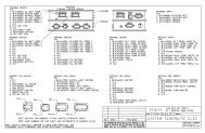
ELECTRICAL SCHEMATIC<br />
200 SERIES BI-AXIS LEVELING SYSTEM<br />
WITH HYDRAULIC ROOM EXTENSION SYSTEM<br />
BATTERY<br />
15 AMP<br />
M<br />
PUMP<br />
MOTOR<br />
PUMP RELAY<br />
CONTACT<br />
FUSED ACCESSORY<br />
(10-15AMP)<br />
FUSED IGNITION<br />
(5-15AMP)<br />
AMP 3PIN UML<br />
6111<br />
CONNECTION<br />
(PURPLE) 6110<br />
1 1<br />
2 2<br />
3 3<br />
(RED) 6120<br />
6111<br />
7699<br />
"JACKS DOWN" LIGHT<br />
ROOM EXTENSION CIRCUIT<br />
PROVIDED BY WINNEBAGO<br />
WARNING BUZZER<br />
7699<br />
BROWN<br />
ROOM CONTROL<br />
SWITCH DPDT<br />
6245<br />
6245<br />
EXTEND<br />
RETRACT<br />
PUMP<br />
RELAY<br />
8600<br />
PUMP/MANIFOLD<br />
ASSEMBLY<br />
(YELLOW) 5000<br />
(BLACK) 5100<br />
(ORANGE) 8601<br />
(WHITE) 6230<br />
AMP 6 PIN<br />
UML CONNECTOR<br />
1<br />
2<br />
3<br />
4<br />
5<br />
6<br />
EXTEND<br />
RETRACT<br />
PUMP<br />
GROUND<br />
JACK SENSE<br />
SW. BATTERY<br />
1<br />
2<br />
3<br />
4<br />
5<br />
6<br />
85 87 87A<br />
+<br />
-<br />
86 30<br />
BOSCH<br />
JOYSTICK<br />
VALVE SWITCH<br />
6231<br />
NOTE: THE (4) DIGIT WIRE NUMBER<br />
SUPERSEDES ANY AND ALL WIRE COLORS.<br />
6230<br />
10 AMP<br />
LR<br />
LF<br />
RF<br />
RR<br />
BLUE<br />
(WHITE) 6230<br />
*(BLUE) 6820<br />
**(BROWN) 7699<br />
(GREEN) 4000<br />
(ORANGE) 1000<br />
(GRAY) 2000<br />
(BLACK) 3000<br />
NC<br />
NC<br />
(RED) 6120<br />
JOYSTICK<br />
LIGHT PANEL<br />
STAINLESS STEEL<br />
GROUND STUD.<br />
JACK WARNING<br />
SWITCHES<br />
HARNESS<br />
SEE PANEL<br />
ELECTRICAL<br />
CONNECTION<br />
DIAGRAM<br />
*NOTE: BLUE IS A POSITIVE SIGNAL<br />
WHEN JOYSTICK PANEL IS ON.<br />
**NOTE: BROWN IS A NEGATIVE<br />
SIGNAL WHEN A JACK IS DOWN.<br />
MP85.9448<br />
08FEB99