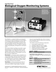
dissolved oxygen monitoring system - Instech Laboratories, Inc.
dissolved oxygen monitoring system - Instech Laboratories, Inc.
dissolved oxygen monitoring system - Instech Laboratories, Inc.

Create successful ePaper yourself
Turn your PDF publications into a flip-book with our unique Google optimized e-Paper software.
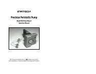
Dissolved Oxygen Measuring System<br />
System 203 Operation Manual<br />
NOTE: This <strong>system</strong> is intended for in vitro physiological and biological studies. It is not intended for use on<br />
humans. <strong>Instech</strong> <strong>Laboratories</strong>, <strong>Inc</strong>. cannot assume liability from improper use of its products.
Printed September 1999<br />
m:\newmanls\proddocs\<strong>oxygen</strong>\oxmanual2.doc<br />
<strong>Instech</strong> <strong>Laboratories</strong>, <strong>Inc</strong>.<br />
5209 Militia Hill Road<br />
Plymouth Meeting, PA 19462-1216
Contents<br />
Set-up...............................................................................................................................3<br />
Setting Up the Chamber ............................................................................................................................3<br />
Preparing the Electrode .............................................................................................................................6<br />
Completing Chamber Set-up .....................................................................................................................7<br />
Setting Up the Amplifier............................................................................................................................8<br />
Calibrating the Amplifier ..........................................................................................................................8<br />
Operation ......................................................................................................................10<br />
Batch Cell Experiments ...........................................................................................................................10<br />
Flow Cell Experiments ............................................................................................................................10<br />
Maintenance ..................................................................................................................11<br />
Electrode Maintenance............................................................................................................................11<br />
Chamber Maintenance............................................................................................................................11<br />
Appendix A: Troubleshooting........................................................................................12<br />
Appendix B: System Theory ...........................................................................................13<br />
Appendix C: Choosing Between High and Low Flow Cells ............................................14<br />
Appendix D: Ambient pO 2<br />
vs. Temperature ...................................................................15<br />
Appendix E: Specifications .............................................................................................16
Set-up<br />
Your Dual Chamber Oxygen Measuring System<br />
(SYS203) should include the following items:<br />
1 Dual Channel Amplifier<br />
1.... Amplifier<br />
2.... 42” output cables<br />
2 Standard Electrodes, each with<br />
1.... Standard <strong>oxygen</strong> electrode with cable<br />
1.... Electrode sleeve<br />
1.... Electrode nose piece<br />
15.. O-rings<br />
1.... O-ring installation tool<br />
1.... 72 in 2 membrane material<br />
1.... 4 in 2 polishing paper<br />
1.... 4 in 2 Scotch-Brite®<br />
2 Batch/Flow Chambers, each with<br />
1.... Chamber block<br />
1.... Batch chamber cup with fill port plug<br />
1.... Batch chamber window<br />
1.... Hamilton syringe fill port plug<br />
1.... Vial of silicone grease<br />
1.... High flow cell<br />
1.... Low flow cell (with white dot)<br />
1.... 10” lengths of 1/8” OD Tygon tubing<br />
1.... 4” lengths of 1/8” OD Tygon tubing<br />
1.... Motor/magnet stirring assembly<br />
1 Dual Channel Stirring Controller<br />
1.... Dual channel precision speed controller<br />
1.... 9 VDC power adapter<br />
1 Electrode Chlorider and Accessory Kit<br />
1.... Electrode chlorider<br />
1.... 9 VDC power adapter<br />
15.. Electrode o-rings<br />
1.... O-ring installation tool<br />
1.... 8 in 2 Scotch-Brite®<br />
1.... 72 in 2 polyethylene membrane material<br />
1.... 24 in 2 electrode polishing paper<br />
This manual describes the set-up for two basic<br />
modes of operation: batch cell mode, for<br />
measuring <strong>dissolved</strong> <strong>oxygen</strong> concentration in a<br />
fixed 600µl sample, and flow cell mode, for<br />
measuring the <strong>oxygen</strong> concentration in fluid as it<br />
passes through the flow cell. For both of these<br />
modes, there are five basic steps to the set-up:<br />
1. Set up the chamber<br />
2. Prepare the electrode<br />
3. Install the electrode and complete the<br />
chamber set-up<br />
4. Set up the amplifier<br />
5. Calibrate the amplifier.<br />
For your convenience, this manual describes the<br />
set-up of the entire <strong>system</strong>; you do not need to<br />
refer to the smaller manuals included with the<br />
electrode or the chamber <strong>system</strong>.<br />
Setting Up the Chamber<br />
These initial steps apply to both the batch and<br />
flow cell modes:<br />
1. Mount the chamber to a ring stand or other<br />
suitable support.<br />
2. Attach a circulating water bath to the inlet<br />
and outlet tubes. The block should be kept at<br />
a constant temperature as the <strong>oxygen</strong><br />
electrode is sensitive to temperature changes.<br />
The fittings are designed for 3/8” ID tubing.<br />
Be sure to secure the tubing with a hose<br />
clamp or cable tie to prevent blow-off.<br />
3
Batch cell chamber assembly<br />
Setting Up the Batch Cell Chamber<br />
The batch cell mode uses the chamber cup with a<br />
magnetic stirring motor mounted behind it. The<br />
chamber cup is sealed with the window valve<br />
which is held in place by a thin layer of silicone<br />
grease.<br />
1. Plug in the speed controller. Plug the AC<br />
adapter into the DC IN jack of the speed<br />
controller first, then plug the AC adapter into<br />
a wall outlet.<br />
2. Plug the motor into MOTOR OUT jack of<br />
the speed controller. The motor should run<br />
when the speed controller is turned on.<br />
3. Temporarily insert the chamber cup into the<br />
chamber block. Push in the red leak<br />
protection divider from the rear of the<br />
chamber block using a pencil until it hits the<br />
chamber cup. The opening should face away<br />
from the chamber cup.<br />
4. Insert the motor/magnet assembly into the<br />
chamber block until it hits the red spacer,<br />
then pull it back about 1 mm.<br />
5. Gently tighten the set screw to hold the<br />
motor using the provided allen wrench.<br />
6. Insert the chamber cup into the front of the<br />
chamber block.<br />
7. Place the stir bar into the chamber cup. It<br />
should couple to the magnet and rotate freely<br />
against the back of the cup when the speed<br />
controller is turned on.<br />
8. Apply a small amount of silicone grease to<br />
the flat front surface of the chamber cup.<br />
Avoid the small fill and overflow port holes.<br />
9. Press the window against the cup and rotate<br />
it to distribute the grease uniformly across the<br />
face.<br />
Silicone<br />
grease<br />
Uniformly<br />
distributed<br />
4
Flow cell chamber assembly<br />
10. Pull off the window valve and clean off<br />
excess grease from the inside of cup using a<br />
toothpick. Check the port holes as well. Do<br />
not clean the layer of grease from the face of<br />
the cup – this will form the seal for the<br />
window.<br />
11. Clean off all grease from the window valve.<br />
An acetone dampened tissue works well.<br />
12. Press the window valve back on to the<br />
chamber cup and rotate to distribute the<br />
grease across the face.<br />
13. Install the appropriate fill port plug into the<br />
top of the chamber. If you plan to use a<br />
plastic-tipped micropipette to add fluid to the<br />
chamber during your experiment, use the<br />
single-piece pipette plug. If you plan to use a<br />
microliter syringe, use the two-piece syringe<br />
plug.<br />
firmly in place. Skip to the section Preparing the<br />
Electrode.<br />
Setting Up the Flow Cell Chamber<br />
The flow cell mode uses one of two flow cells<br />
provided with your <strong>system</strong>: the low-flow cell for<br />
flow rates less than 15 ml/minute, the high-flow<br />
cell for rates greater than 15 ml/minute. (See<br />
Appendix for more details.) The low flow cell<br />
has a white dot on it. The various pieces of<br />
equipment designed for the batch cell mode (i.e.,<br />
speed controller, motor, chamber cup, window<br />
valve, and red spacer) are not needed and should<br />
be set aside.<br />
Low flow cell<br />
Pipette plug<br />
High flow cell<br />
Syringe plug<br />
The chamber is now ready for the electrode.<br />
When inserted, the electrode will hold the cup<br />
Most in-line experiments involve measuring the<br />
difference in <strong>oxygen</strong> level at two points in a<br />
<strong>system</strong>, and thus will require that you set up two<br />
flow cells.<br />
5
To set up the flow cell chamber:<br />
1. Insert chosen flow cell into the chamber<br />
block from the front. Be sure that batch cell<br />
parts have been removed from the chamber<br />
block and that the set screw does not<br />
protrude into the hole.<br />
2. Attach inlet and outlet tubes of your<br />
experiment to the flow cell. The <strong>system</strong> is<br />
designed for 1/16” ID tubing, such as Tygon.<br />
The flow cell is now ready for the electrode.<br />
Preparing the Electrode<br />
Oxygen electrodes need to be prepared with fresh<br />
electrolyte and a new membrane before each use.<br />
1. Prepare fresh KCl solution daily. The<br />
solution should be about 1/2 saturated (add<br />
about 15 gms KCl to 100 ml water).<br />
Concentration is not critical, purity is.<br />
2. Remove the old membrane and rinse the<br />
electrode tip with water, if it has been<br />
previously used.<br />
3. Slide the electrode sleeve over the electrode.<br />
Be sure the sleeve is clean, or it may damage<br />
the electrode tip.<br />
4. Roll an o-ring onto tapered end of the<br />
installation tool and position it as close as<br />
possible to the flat end by holding the flat end<br />
against a tabletop and rolling the o-ring to<br />
the bottom.<br />
5. Lay a sheet of membrane material<br />
(approximately 1” by 1”) on the top of the<br />
installation tool. The best material for<br />
membranes is usually common polyethylene<br />
sandwich bags. (See System Theory for more<br />
details.) Be careful not to touch the area of<br />
the membrane that you will be using.<br />
6. Dip the electrode tip into the KCl solution<br />
and allow a droplet to form.<br />
7. Place this drop on the membrane over the<br />
hole in the installation tool.<br />
8. Dip the electrode tip into the KCl again.<br />
9. Press the tip with the hanging droplet into the<br />
depression in the installation tool.<br />
10. Roll the o-ring off the tool and into the<br />
groove on the electrode to secure the<br />
membrane.<br />
11. Examine the tip of the electrode; if you see an<br />
air bubble, install a new membrane.<br />
12. Cut off excess membrane using a sharp knife<br />
against the silver body of the electrode.<br />
The electrode is now ready to be installed into<br />
your chamber set-up. If you plan to use the<br />
electrode outside the chamber block, screw the<br />
electrode nose piece onto the electrode sleeve.<br />
This will form a seal against the o-ring and<br />
prevent solution from leaking behind the<br />
membrane.<br />
6
Install the electrode quickly; if it is exposed to dry<br />
air for much more than one minute, the<br />
electrolyte will evaporate and you will need to<br />
install a new membrane.<br />
If you are using this electrode for the first time,<br />
you may wish to determine the true electrode zero<br />
offset before installing the electrode in your<br />
<strong>system</strong>. (Skip to the section Calibrating the<br />
Amplifier - Determining True Zero and return to<br />
Completing Chamber Set-Up when finished.<br />
FILL/RINSE<br />
position<br />
SEALED<br />
position<br />
Completing Chamber Set-up<br />
Completing Batch Cell Chamber<br />
To complete the batch cell chamber set-up, you<br />
need to install the electrode and fill the chamber<br />
with your buffer solution.<br />
Electrode<br />
Overflow<br />
tube<br />
chamber cup holes. You must be careful not<br />
to have any air bubbles trapped in the<br />
chamber as this will obviously distort your<br />
measurements. Positioning the stir bar<br />
vertically by jogging the speed controller on<br />
and off will help. If you do get an air bubble,<br />
suck the solution back into the syringe and<br />
try again.<br />
2. Turn the window valve to the SEALED<br />
position.<br />
3. Turn on the stirring motor and the circulating<br />
water bath.<br />
Your batch cell chamber is now set up. Skip to<br />
the section Setting Up the Amplifier.<br />
Fill tube<br />
1. Align cup and chamber block electrode holes<br />
and insert electrode. Gently screw in the<br />
electrode sleeve so that the o-ring forms a seal<br />
against the cup. Be careful not to puncture<br />
the membrane during this process.<br />
2. Attach the overflow tube to the top of the<br />
chamber. Be sure that the other end of the<br />
tube is above the top of the chamber cup,<br />
otherwise it may siphon out the chamber.<br />
Place a beaker under the tube to collect the<br />
overflow.<br />
3. Attach the fill tube to the bottom of the<br />
chamber.<br />
1. Fill the chamber with buffer solution using a<br />
syringe inserted into the fill tube. The<br />
window valve must be turned to the<br />
FILL/RINSE position with both depressions<br />
in the window valve aligned with the<br />
Completing Flow Cell Chamber<br />
1. Align flow cell and chamber block holes and<br />
insert electrode. Gently screw in the electrode<br />
sleeve so that the o-ring forms a seal against<br />
the cell. Be careful not to puncture the<br />
membrane during this process.<br />
2. Fill the flow cell with solution. Be sure to do<br />
this within one minute after preparing the<br />
electrode to prevent evaporation of the<br />
electrolyte.<br />
Your flow-cell chamber is now set up.<br />
7
Setting Up the Amplifier<br />
1. Plug in the amplifier power cord.<br />
2. Attach the electrode cable to the jack on the<br />
front panel of the amplifier. (A In or V In<br />
depending on which channel you are<br />
connecting.)<br />
3. Attach a chart recorder or other data<br />
acquisition device to the appropriate output<br />
jack on the back of the amplifier. The output<br />
on the Selector jack depends on the setting of<br />
the Mode switch on the front panel (A, V or<br />
AV).<br />
A channel controls<br />
Electrode<br />
input<br />
Mode selector switch<br />
for LED display and<br />
Selector output jack<br />
V channel controls<br />
Calibrating the Amplifier<br />
Finally, you should calibrate the amplifier to<br />
convert the nanoamp electrode current into the<br />
desired reading on the meter, e.g. mmHg of<br />
<strong>oxygen</strong>. This is done by adjusting the Zero<br />
control so that the amplifier reads zero when the<br />
electrode is turned off (or for a more accurate<br />
reading, when the electrode is exposed to an<br />
<strong>oxygen</strong> depleted solution), then by adjusting the<br />
Gain so that the meter reads the true ambient pO 2<br />
with the electrode on.<br />
Quick Zero Calibration<br />
This calibration approximates a zero <strong>oxygen</strong> level<br />
by turning off the electrode sensor. In practice, a<br />
healthy electrode will read 1 to 10 mmHg even<br />
when the <strong>oxygen</strong> level is zero due to minor<br />
imperfections. If this accuracy is important to<br />
your experiment, skip to the section Determining<br />
True Zero.<br />
1. Turn on the amplifier.<br />
2. Set the Gain of the channel you are working<br />
with so that the number on the knob reads<br />
approximately 2 (a fairly high setting).<br />
3. Turn the electrode sensor switch off.<br />
4. Turn the Zero knob so that the LED meter<br />
reads zero. Lock the knob in that position<br />
with the lever on the side of the knob.<br />
5. Turn the Gain back down so that the knob<br />
reads about 1.<br />
6. Turn the electrode sensor switch back on.<br />
Skip to the section Setting Amplifier Gain.<br />
Output jacks: A Channel, V<br />
Channel, or Selector<br />
Meter full scale = +5 V<br />
System Gain: Low<br />
position increases<br />
meter range by a<br />
factor of 10<br />
8
Determining True Zero<br />
A healthy electrode will deliver a small current,<br />
equivalent to 1 to 10 mmHg, even when the<br />
<strong>oxygen</strong> concentration is zero. Complete this<br />
procedure to determine this offset so that it may<br />
be subtracted electronically. Unless you suspect a<br />
problem, you do not need to repeat this<br />
procedure each time you use the electrode.<br />
Electrode with<br />
nose piece in<br />
<strong>oxygen</strong>-depleted<br />
solution<br />
1. Remove the electrode from the chamber<br />
block. It should still be connected to the<br />
amplifier.<br />
2. Screw black nose piece onto electrode to seal<br />
membrane. Do not immerse the electrode<br />
into any solutions outside the chamber<br />
without this sleeve in place.<br />
3. Immerse the tip into a vial with a small<br />
amount of distilled water and allow the<br />
<strong>system</strong> to stabilize.<br />
4. Adjust the amplifier Zero so that the meter<br />
reads 0 with the electrode sensor switch<br />
turned off.<br />
5. Turn on the electrode and set the amplifier<br />
Gain so that the LED meter reads about 150<br />
(the approximate ambient pO 2<br />
of water in<br />
mmHg).<br />
6. In another vial, dissolve about 25 mg of<br />
sodium dithionite into 1 ml of water. Sodium<br />
dithionite chemically removes <strong>dissolved</strong><br />
<strong>oxygen</strong> from the solution.<br />
7. Place the electrode tip into the sodium<br />
dithionite solution. The meter reading should<br />
immediately fall.<br />
8. Check the LED meter after the reading is<br />
stable for one minute. If it reads less than 10<br />
mmHg, the electrode is in good working<br />
condition If the meter reads greater than 10<br />
mmHg, add small amounts of sodium<br />
dithionite until no further drop is observed.<br />
If the meter still reads greater than 10 mmHg,<br />
refer to the Troubleshooting section of this<br />
manual.<br />
9. Adjust the amplifier Zero so that the meter<br />
reads 0 and lock the knob in that position.<br />
10. Rinse the electrode tip well with distilled<br />
water, remove the nose piece, rinse again, and<br />
return it to the chamber block.<br />
You have now calibrated the amplifier to offset<br />
the small signal the electrode delivers when the O 2<br />
level is zero.<br />
Setting Amplifier Gain<br />
1. Allow the <strong>system</strong> to stabilize. The <strong>oxygen</strong><br />
chamber should contain your buffer solution.<br />
The temperature should be held constant<br />
with the circulating water bath. After a few<br />
minutes the meter reading should become<br />
constant.<br />
2. Calculate the ambient pO 2<br />
for your solution.<br />
You can refer to the charts in the appendix,<br />
or use the Intake <strong>oxygen</strong> data acquisition<br />
software to make these calculations for you.<br />
3. Adjust the Gain so that the meter reads the<br />
correct ambient pO 2<br />
. If you are working<br />
with 95% <strong>oxygen</strong> solutions (i.e., a pO 2<br />
of<br />
about 700 mmHg) you will need to set the<br />
System Gain switch on the rear panel of the<br />
amplifier to the low position.<br />
The <strong>system</strong> is now completely set up and<br />
calibrated. You may begin your experiment.<br />
9
Operation<br />
This section describes the basics of operating the<br />
<strong>system</strong> in the batch cell and flow cell modes.<br />
Batch Cell Experiments<br />
Once the <strong>system</strong> has been set up and has<br />
stabilized, a typical experiment begins with the<br />
addition of cells or drugs to the chamber.<br />
Micropipette<br />
addition<br />
ADD position<br />
1. Turn the window valve to the ADD position.<br />
This opens the top overflow port, but keeps<br />
the bottom port closed.<br />
2. Remove the fill port plug from the top of the<br />
chamber and inject cells or drugs. If you are<br />
using a plastic tipped micropipette, remove<br />
the entire single-piece pipette plug. If you are<br />
using a microliter syringe, use the two-piece<br />
syringe plug and remove only the top part.<br />
Excess fluid should drain out through the<br />
overflow tube. Be careful not to inject air<br />
bubbles into the chamber with the pipette.<br />
3. Replace the plug and turn the window valve<br />
to the SEALED position to close off the<br />
chamber from the atmosphere (see figures on<br />
page 7).<br />
4. When your <strong>oxygen</strong> measurement is complete,<br />
open the window valve to the FILL/RINSE<br />
position and flush out the chamber with<br />
buffer solution from the syringe. You are<br />
now ready to take another measurement.<br />
Flow Cell Experiments<br />
Typical flow cell experiments involve measuring<br />
the <strong>oxygen</strong> consumption of some perfused tissue<br />
or device by measuring the difference in <strong>oxygen</strong><br />
level of a flowing solution immediately before<br />
and after the object.<br />
Set up your experiment so that the two flow cells<br />
are as close as possible to the experimental<br />
preparation. Keep all parts of the <strong>system</strong> at a<br />
constant temperature.<br />
To calibrate the amplifier, insert a length of<br />
tubing to bypass the preparation, directly<br />
connecting the two flow cells. Adjust both<br />
electrodes to the pO 2<br />
of the flowing solution. The<br />
difference should be zero. The flow rate of the<br />
solution during calibration should be the same as<br />
the flow rate during the experiment. Reconnect<br />
the experimental preparation, and set the<br />
amplifier to A-V to measure the difference<br />
between the two flow cells.<br />
A varying flow rate across the electrode surface<br />
may vary the reading by several percent,<br />
particularly at lower flow rates. Check the graph<br />
the appendix to determine if this will be a<br />
problem for your experiment.<br />
10
Maintenance<br />
Electrode Maintenance<br />
With proper care, your <strong>oxygen</strong> electrode should<br />
last for many years. You will need to rechloride<br />
the tip periodically, as the Ag-AgCl layer will<br />
become contaminated or wear off under normal<br />
use.<br />
Storage and Cleaning<br />
Store the electrode with its membrane and o-ring<br />
in place. The electrolyte will evaporate, but the<br />
membrane will protect the electrode tip. When<br />
you are ready to use the electrode again, remove<br />
the old membrane, rinse, and install a new one.<br />
You should only rinse the electrode tip with<br />
water. When working with the electrode, be very<br />
careful not to get any solutions near the<br />
connectors. Salty connectors cannot be cleaned<br />
and must be replaced.<br />
Rechloriding<br />
This procedure replaces the Ag-AgCl layer on the<br />
tip of the electrode. This layer is critical to the<br />
electrode operation, and will wear off under<br />
normal use. Excessively high or drifting signals<br />
are signs that you should rechloride the electrode.<br />
1. Remove the old chloride layer with the gray<br />
pad of Scotch-Brite® included in the<br />
accessory kit. The tip should become a bright<br />
silver. Avoid touching the platinum cathode<br />
at the center of the tip. Rinse the tip with<br />
water when you are finished.<br />
2. Plug in the Clorider and fill the clean cup<br />
with fresh KCl solution.<br />
3. Clip in the electrode.<br />
4. Repeatedly dip the electrode tip into the<br />
Chlorider cup until it becomes a uniform dull<br />
gray (this usually takes about 1 minute).<br />
Avoid touching the electrode to the sides of<br />
the cup. If the coating is not uniform, the tip<br />
probably was not clean enough; you should<br />
remove this layer and start over.<br />
With a new membrane, your electrode will be<br />
ready to use.<br />
Tip Renovation<br />
If the electrode tip becomes contaminated with<br />
protein or if the epoxy around the glass seal<br />
swells, complete this procedure. You should not<br />
have to renovate the tip frequently.<br />
1. Place the fine gray polishing paper (provided<br />
in the accessory kit) on a flat surface and put<br />
a few drops of water on the paper.<br />
2. Holding the electrode perpendicular to the<br />
paper, rub the tip until a fresh layer of<br />
platinum has been exposed at the center.<br />
Usually this takes only 3-5 passes.<br />
3. Rechloride the electrode.<br />
Chamber Maintenance<br />
It is not normally necessary to clean the chamber<br />
cup or the flow cell after each use; simply flushing<br />
the cell with your buffer solution should suffice.<br />
Occasionally, you should dismantle the chamber<br />
set-up and clean the parts with alcohol or another<br />
disinfectant to prevent bacteria buildup. If<br />
bacteria exist in your <strong>system</strong>, you will probably<br />
notice their <strong>oxygen</strong> consumption during your<br />
experiment.<br />
11
Appendix A: Troubleshooting<br />
Symptom<br />
Signal drifts and is<br />
excessively high<br />
Signal wanders at typical<br />
levels<br />
Signal drifts downward<br />
steadily, but returns to<br />
normal levels with refilling of<br />
chamber<br />
Zero pO 2<br />
level (as established<br />
by Determining True Zero<br />
procedure) is greater than<br />
7% of ambient<br />
Transient spikes during small<br />
additions to chamber<br />
Electrode does not respond<br />
when sensor turned on<br />
Potential problem<br />
Membrane perforated<br />
Salt bridge in cable or electrode<br />
connectors<br />
Chloride layer contaminated<br />
System temperature not sufficiently<br />
stable<br />
Air bubble on or under membrane<br />
Solution not stirred sufficiently (batch<br />
cell mode)<br />
Varying flow rate of solution across<br />
electrode tip (flow cell mode)<br />
Chloride layer contaminated<br />
Foreign material on platinum<br />
cathode surface<br />
Hydrostatic pressure changes<br />
effecting membrane stability<br />
Chamber contaminated with bacteria<br />
Not enough sodium dithionite<br />
Chloride layer contaminated<br />
Defective glass to platinum seal<br />
Temperature of injected solution<br />
different from <strong>system</strong> temperature<br />
Heat of dissolution due to addition of<br />
a non-aqueous solution (e.g. alcohol<br />
or DMSO)<br />
Air or insufficient electrolyte under<br />
membrane<br />
Electrode or cable leads broken<br />
Amplifier faulty<br />
Treatment<br />
Remove electrode and check for holes in the<br />
membrane. If present, clean and rechloride<br />
electrode.<br />
Remove electrode from chamber, remove<br />
membrane and dry electrode tip. pO 2<br />
level<br />
should read zero; if not, replace electrode and<br />
cable.<br />
Clean and rechloride electrode.<br />
Use well controlled circulating water bath.<br />
Remember that the temperature coefficient of<br />
the electrode is approximately 4%/°C.<br />
Dislodge external bubble or replace membrane.<br />
Turn on or increase speed of stirring motor.<br />
Use low flow cell or modify experiment to<br />
stabilize flow rate.<br />
Clean and rechloride electrode.<br />
Renovate electrode tip.<br />
No known remedy.<br />
Disassemble and clean all chamber parts.<br />
Alcohol or Clorox will usually kill any growths.<br />
Add more dithionite in small steps to titrate<br />
down to a minimum reading. Be careful not to<br />
use excessive amounts of dithionite, as it will<br />
damage the chloride layer.<br />
Clean and rechloride electrode.<br />
Replace electrode.<br />
Equilibrate injectate to <strong>system</strong> temperature<br />
Signal not valid during transient; may be<br />
removed mathematically.<br />
Visually inspect electrode tip. Reinstall<br />
membrane if required.<br />
Remove electrode membrane and dip tip into<br />
deionized water with sensor turned on. The<br />
amplifier should register a very large reading. If<br />
not, the leads are probably broken; replace the<br />
electrode and cable.<br />
Test the suspect amplifier channel with another<br />
electrode, if available. Call for technical<br />
assistance.<br />
12
Symptom<br />
Response to <strong>oxygen</strong> good,<br />
but signal level has gradually<br />
increased over a period of<br />
weeks<br />
Response to <strong>oxygen</strong> good,<br />
but signal level has gradually<br />
decreased over a period of<br />
weeks<br />
Potential problem<br />
Platinum cathode surface may have<br />
become roughened, increasing the<br />
active surface area and therefore the<br />
current<br />
Platinum cathode has become<br />
coated or poisoned<br />
Treatment<br />
Renovate electrode tip.<br />
Renovate electrode tip.<br />
Appendix B: System Theory<br />
This <strong>dissolved</strong> <strong>oxygen</strong> measuring <strong>system</strong> is<br />
designed around a style of polarographic<br />
electrode developed by Dr. Leland Clark.<br />
When a potential of about 0.7V is applied<br />
between the anode and the cathode, <strong>dissolved</strong><br />
gaseous <strong>oxygen</strong> is reduced at the platinum<br />
cathode. This produces a current and consumes<br />
the <strong>oxygen</strong> in the immediate vicinity of the<br />
exposed platinum cathode. Oxygen in the sample<br />
volume diffuses through the membrane to the<br />
<strong>oxygen</strong>-poor region between the membrane and<br />
the electrode. When a steady-state is reached<br />
(which usually happens in less than 4 seconds),<br />
the electrode current is proportional to the rate of<br />
arrival of <strong>oxygen</strong> molecules at the cathode, which<br />
is in turn proportional to the concentration of<br />
<strong>oxygen</strong> outside the membrane.<br />
The <strong>oxygen</strong> amplifier does two things: (1) it<br />
generates the electrode biasing potential and (2) it<br />
measures the electrode current, usually only a few<br />
nanoamps, and converts it to a voltage.<br />
The electrode is quite sensitive to temperature<br />
changes as temperature affects the speed of the<br />
chemical reaction, the ease of diffusion across the<br />
membrane and the ambient <strong>oxygen</strong> concentration<br />
of the sample solution. Electrode readings will<br />
increase by about 4% for a temperature increase<br />
of 1°C.<br />
In order to make an accurate measurement of<br />
<strong>oxygen</strong> levels in the entire sample volume, the<br />
<strong>oxygen</strong> around the outside of the membrane must<br />
be replaced. If the sample is not adequately<br />
stirred when working in batch cell mode, or if the<br />
flow rate is too low when working in flow cell<br />
mode, a concentration gradient will be set up<br />
outside the membrane and the rate of arrival of<br />
<strong>oxygen</strong> at the electrode will decrease. Slight fluid<br />
velocity changes will produce a “motion artifact”.<br />
The type of material used as a membrane also<br />
critically affects the performance of the <strong>system</strong>.<br />
We have found that 0.001” to 0.0009” thick<br />
polyethylene, which is readily available from<br />
normal sandwich bags, works best. Membranes<br />
that are more <strong>oxygen</strong> permeable, such as TFE<br />
Teflon or silicone, may be required for<br />
experiments at low temperatures or when a<br />
response rate faster than 4 seconds is desired.<br />
However, these materials will cause a greater<br />
motion artifact because the concentration<br />
gradient extends further into the bulk solution.<br />
TFE Teflon will also stretch and thin over time,<br />
causing the initial amplifier calibration to become<br />
incorrect. FEP Teflon usually works well, but is<br />
too stiff to wrap around the small electrode tip.<br />
Saran is not sufficiently permeable to <strong>oxygen</strong> to<br />
be useful as a membrane.<br />
13
Appendix C: Choosing Between High and Low Flow Cells<br />
When using the flow cells at low flow rates, an<br />
<strong>oxygen</strong> concentration gradient may be set up<br />
outside the membrane (see System Theory) which<br />
will cause the electrode to read lower than it<br />
otherwise would. Other than a slight loss in<br />
signal strength, this effect should not be a<br />
problem so long as the amplifier is properly<br />
calibrated and the flow rate does not vary. Use<br />
the following chart to understand whether this<br />
will affect your experiment, and to choose the<br />
best flow cell for your set-up. Typically you will<br />
want to use the low flow cell unless your flow<br />
rates are greater than 15 ml/minute and the back<br />
pressure that the low flow cell generates will<br />
bother your experiment.<br />
100<br />
99<br />
98<br />
97<br />
Low flow cell<br />
High flow cell<br />
Percent of true reading<br />
96<br />
95<br />
94<br />
93<br />
92<br />
91<br />
90<br />
0 5 10 15 20 25 30<br />
Flow rate of solution across electrode tip (ml/min)<br />
14
Appendix D: Ambient pO 2<br />
vs. Temperature<br />
Use the following chart to help calibrate the<br />
amplifier when using buffer solutions equilibrated<br />
with air. When using 95% <strong>oxygen</strong> solutions,<br />
multiply these values by 95/20.9.<br />
180<br />
170<br />
160<br />
150<br />
140<br />
130<br />
165.7<br />
157.4<br />
149.0<br />
140.6<br />
132.3<br />
Atmospheric pressure<br />
840 mmHg<br />
800 mmHg<br />
760 mmHg<br />
720 mmHg<br />
120<br />
680 mmHg<br />
110<br />
100<br />
0 5 10 15 20 25 30 35 40 45 50<br />
T (celsius)<br />
* pO 2<br />
= .209 x (atmospheric pressure – vapor pressure of water)<br />
Source: CRC Handbook (for tables of vapor pressure of water vs. temperature).<br />
15
Appendix E: Specifications<br />
Electrode (model 125/05)<br />
• Length<br />
• Body diameter<br />
• Typical current at ambient pO 2<br />
• Time constant, polyethylene membrane (0-63%)<br />
• Mating connector (Amphenol part no.)<br />
Chamber (model SYS600)<br />
• Batch cell cup volume — with stir bar<br />
• Tube required for water bath connection<br />
• Tubing required for overflow and fill ports<br />
Amplifier (model 203)<br />
• Size (WxLxH)<br />
• Weight<br />
• Power requirements — standard model<br />
• Power requirements — European model<br />
• Rear panel analog output voltages<br />
1.635<br />
0.125<br />
18<br />
<strong>Instech</strong> <strong>Laboratories</strong>, <strong>Inc</strong>.<br />
<strong>Instech</strong> has been a leading provider of instruments<br />
for medical and biological research for over 25<br />
years. Our reputation for quality and reliability<br />
is recognized by research facilities, universities<br />
and a wide range of companies throughout the<br />
world.<br />
Our design and manufacturing<br />
capabilities include:<br />
• Laboratory animal infusion <strong>system</strong>s<br />
• Precision syringe and peristaltic pumps<br />
• Dissolved <strong>oxygen</strong> measurement <strong>system</strong>s<br />
• Cuvette stirring <strong>system</strong>s<br />
• New product design and development<br />
For more information on the complete line of<br />
<strong>Instech</strong> <strong>system</strong>s and custom products, visit our<br />
website or call us toll-free at 1-800-443-4227.<br />
The equipment behind the science.<br />
<strong>Instech</strong> <strong>Laboratories</strong>, <strong>Inc</strong>.<br />
5209 Militia Hill Road<br />
Plymouth Meeting, PA 19462-1216<br />
800-443-4227 • 610-941-0132<br />
FAX 610-941-0134<br />
EMAIL support@instechlabs.com<br />
WEB http://www.instechlabs.com